
I had been looking for a good ADC board for lab use as a measurement device.
At first I considered making my own, using something like the TI PCM4222 ADC chip, due to its excellent performance, good availability and relative ease of build.
But then I got lazy and purchased the PCM4222 EVM instead:
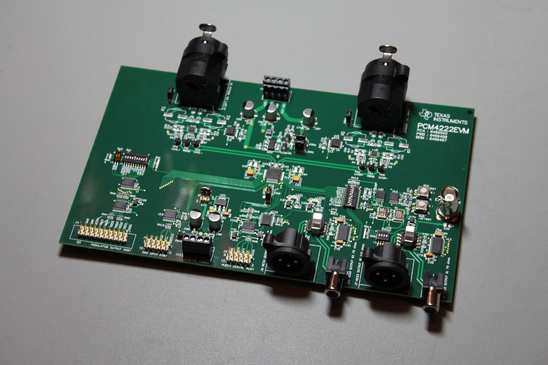
It is a 4-layer, well designed and implemented board.
Besides the necessary 2 clocks, it has a full set of digital outputs:
– Dual AES3 compatible outputs (both coaxial at 75Ω and XLR at 110Ω)
– I2S
– DSD
– Raw, directly from the modulators
Its analog inputs are balanced and very low noise.
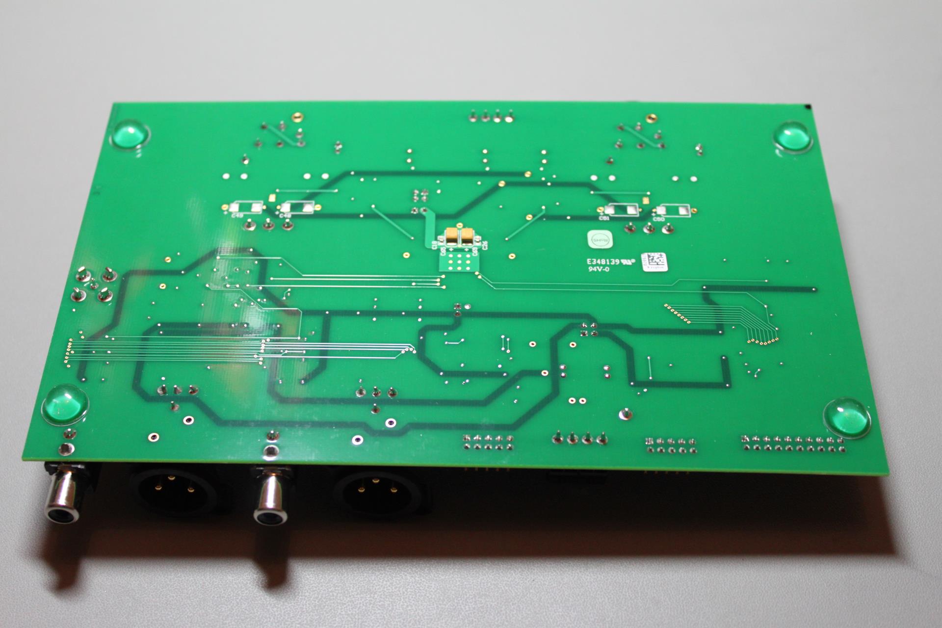
Make no mistake, this is an evaluation module. As such, there are no mounting holes. Just four rubber “feet”:
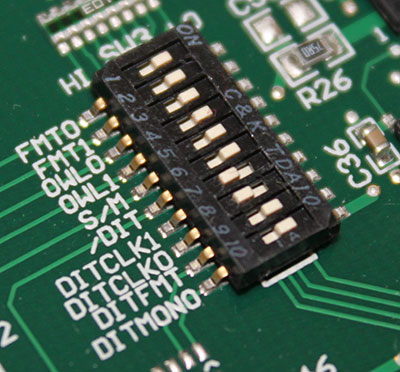
Since I was in a hurry to get it to work, I set it up for operation with the least amount of power supplies (+/-15VDC and +5VDC) and set the DIP switches for I2S operation at 24bit and 96KHz.
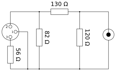
I wanted to use one of its built-in AES3 outputs, but my sound card only had consumer level s/pdif inputs. After a short Google search, this came up: http://www.rane.com/note149.html
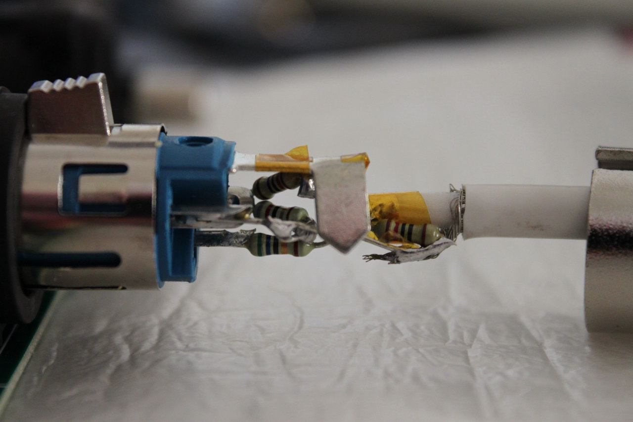
In other words, I had to make a 75Ω cable, with an XLR at one end, an RCA plug at the other and this circuit embedded in the XLR plug:
Surprisingly enough, it fit.
I hooked it up to the ‘scope to see if everything looked OK, and after being satisfied with what I saw I hooked it up to my X-Meridian’s coax s/pdif input. The sound mixer in Windows showed a full level signal coming out of it but it was heavily distorted. What was going on?
While troubleshooting, I tried the serial output port by connecting it to a WM8804 board that I had lying around. Sure enough, I got proper undistorted s/pdif output, so the PCM4222 was working as it should. So the problem had to be in the AES3 drivers.
After some more Googling I came across a post in some forum by someone who had a similar problem with me. He said that for some reason he had to set the ADC’s output to Left Justified (instead of I2S) in order to get the AES3 transmitters to output a proper signal. I made the necessary changes to the microswitches and lo and behold, it worked!
This is the configuration that I ended up with:
Next up is a proper input stage, since the ADC has balanced inputs but most of my equipment-under-test is single ended.
Hi Dimdim,
Have you made any further progress with the PCM4222?
I came across the threads over at gearslutz and then found your posts while trying to find more information. I’m thinking that combing this with a miniDSP usbstreamer might make a killer ADC for testing.
I’d personally just use the balanced inputs with RCA to Balanced cable and be done with it.
cheers
Paul
Hi Paul,
I haven’t had a chance to work on it yet. When I first got it, I tried using an RCA to Balanced cable (actually it was the first thing I tried) but the levels were way too low, especially with the 0.7VRMS that the DAM’s SE output puts out.
So I designed a simple input stage (SE to balanced converter with a little gain) but put it on hold because I realized that I would also need an attenuator since I would want to measure both low-output sources (like the DAM) as well as full 2VRMS sources. So I thought I would go with an R-2R attenuator. To make it fun, I thought I would design it and build it from scratch, so I bought the parts for a prototype, but then got sidetracked by other projects.
I too thought I would combine it with the miniDSP (since it’s the only async USB interface with I2S input that is not terribly expensive) but realized that I couldn’t get it shipped to Greece without it costing way more than I thought it should. Then the capital controls came and made things even more difficult, so I though I would stick with the coax output for the time being.
I believe I will find time to sort things out in the following months – I really would like to be able to measure with accuracy the things I do to the DAM :P. And yes, I too will probably give up and start measuring the DAM from its balanced outputs, even though it feels wrong. 😛
One last thing, I plan on powering the ADC from Salas shunt power supplies. It is definitely overkill, but it will give me a chance to try the Salas 1.2R shunt regs (I’ve been meaning to build a few for some time now).
Hi Dimdim,
Good to hear that the project is still ticking away. I’ve got an EVM board on order and it’s due for delivery in about a week.
I can see the issue with the gain for SE inputs. The PCM4222 has a maximum differential input voltage of just under 2Vrms, and the input stage is configured with a gain of 0.4821 (270R/560R), so you need around 4.1Vrms on the inputs for 0dBFS output.
I guess you could alter the gain to unity or greater on the input diff amps and then attenuate as required with balanced signals?
The clocking look OK but nothing spectacular. I’m sure a dedicated DIYer could do far better. 🙂 At least there is option for using external power to bypass the LM1117-3.3 and LM1117-5.0 regs.
I might patch in a Toslink TX in place of one of the AES/SPDIF outputs to get up and running. My laptop has optical input so saves buying more hardware and will avoid the dramas with I2S isolation on a usb interface. The DIT4192 seems like it should be OK. The original HiFace used the DIT4192 to drive SPDIF so obviously isn’t too shabby 😉
I’ll post something up once I get the board.
cheers
Paul
Pingback: DIYINHK XMOS Multichannel 32ch USB to/from I2S/DSD SPDIF Interface | Dimdim's Blog
DimDim Thank you. Same problem with I2S settings