
A while back a thread was started at avclub.gr discussing the design of a sampling rate indicator board for a JLSounds I2SoverUSB interface.
As the conversation progressed, it became apparent that a more versatile solution would be preferrable. Such a solution would be compatible with most of the available USB interfaces, such as the Amanero Combo384, the DIYINHK XMOS interface, the JLSounds I2SoverUSB interface, the WaveIO, etc.
It would also have to be better looking. A bunch of LEDs just wouldn’t cut it. It was decided that a small OLED display was a better idea. There was also a request that classic 7-segment LED displays be supported. Finally, it was to be galvanically isolated from the USB to I2S interface that it was monitoring.
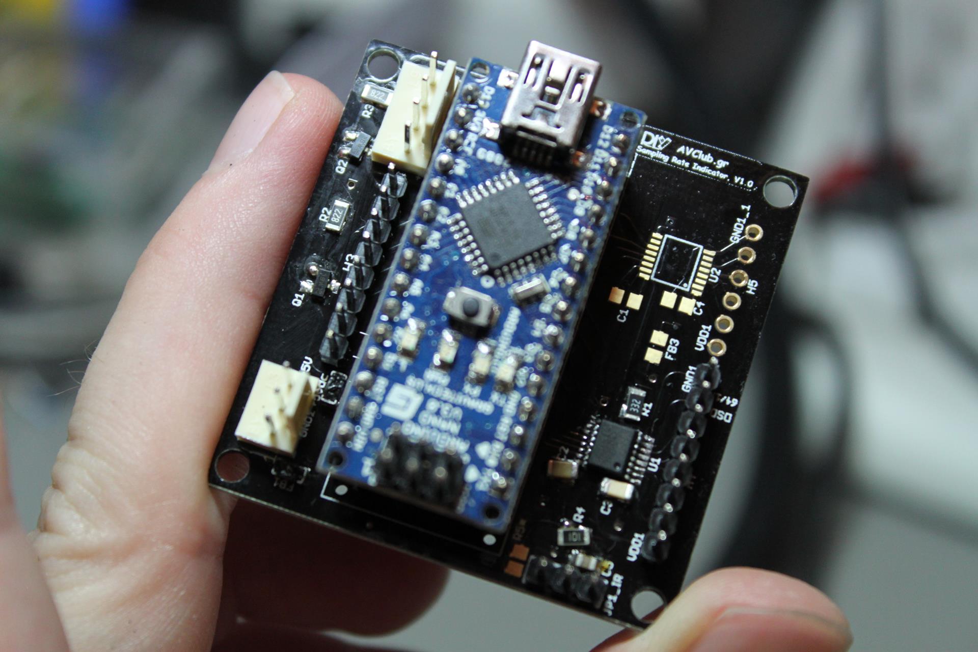
Thus was born the Arduino-based Universal USB to I2S Interface Indicator.
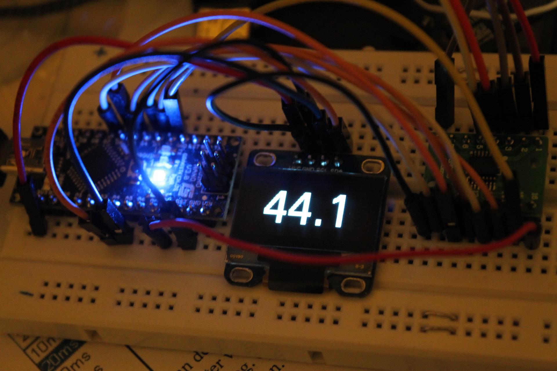
It is based on the Arduino Nano and sports a 0.96″ or 1.3″ OLED display with a resolution of 128 x 64.
From the beginning it became obvious that the Arduino Nano would be a no brainer for this application. It is small, thus it does not take up too much PCB real estate. It has more than enough I/O for our application. It includes a USB port for easy programming. It is readily available and it costs just a few Euros.
The screen was more of a conversation piece. It was decided that a TFT would be overkill, since we only needed to display a sampling rate, or at most also the signal type (PCM or DSD).
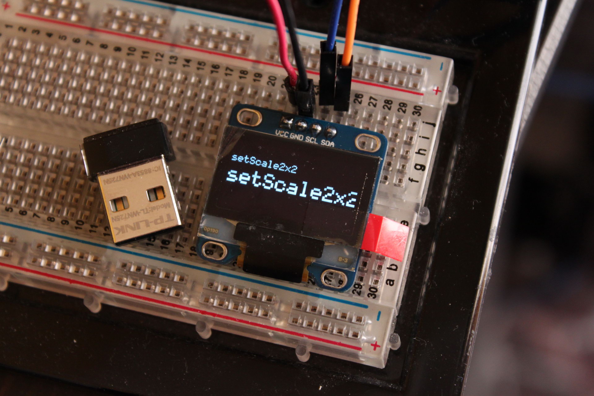
I pitched the idea of a small OLED display, something low-cost and easy to come by. Luckily, Ebay has tons of 0.96″ and 1.3″ OLEDs for a few Euros. They can be had with either SPI or I2C interfaces.
It was requested that 7-segment LED displays be supported as well and the easiest way to do that was to use a LED driver IC that would communicate with the Nano over I2C. Like this one.
Since we would be using I2C for the LED display, it made sense to also use it for driving the OLED display. We decided to go with one like this one. It is just 0.96″ in diagonal and has a resolution of 128 x 64, but we wouldn’t be needing anything bigger. Here it is, next to a USB WiFi adapter for scale:
The requirement of driving the LED display eventually went away, but the I2C interface for the OLED display remained.
Next up, we wanted electrical isolation. Silicon Labs’ isolators came to mind, since they are reasonably priced and readily available. Plus, I have a lot of experience with them. We chose to use two ICs, an Si8065 and an Si8045. The idea was to install the Si8065 and if more than 6 sense lines were needed to also install an Si8045 for another 4.
Later on in the development cycle we decided to make the project a little more universal, so now for the second isolator the end user may choose between the Si8045 or the Si8642, getting respectively 4 more inputs or 2 inputs and 2 outputs.
We also decided to support IR remote functionality. This way we could give the project remote control capabilities such as remote power on/off and source selection. The library that I have used supports a long list of IR protocols.
So, that covered the hardware. On to the software.
The code is pretty simple, really.
It’s just a few digital inputs with code to recognise the various combinations of digital highs and lows of the various USB interfaces and some code to drive the OLED accordingly.
I am using the excellent u8glib library to drive the OLED and the also excellent IRremote Library for the IR stuff.
The IRremote library supports all kinds of remotes so you shouldn’t have much trouble finding a suitable one. The current version of the code is set to decode all IR signals and to send through the serial port the IR codes that it does not recognise as valid commands. This way it is easy to discover a working remote and to find out the exact IR code that you should put in the relevant section:
#define POWER_CODE 0xFF48B7 // Code for power on/off

#define SOURCE1_CODE 0xFF827D // Code for source 1

#define SOURCE2_CODE 0xFFB24D // Code for source 2
The custom PCB that has been designed for this project has 10 sense lines, labeled I1 to I10. They correspond to D2 through D11 of the Nano. Optionally, instead of 10 sense (input) lines, it may be built to support 8 inputs and 2 outputs. More details can be found on the PCB’s post. It also has a header bringing out the unused I/O of the Nano, for future use.
It was also meant to support the connection of an IR decoder module to Pin A7. At the time of the PCB design I was under the impression that it was possible to use pin A7 as a digital input for the IR sensor but that proved to be false. It turns out that the necessary function pulseIn() requires a real digital line. A solution is to connect pin 1 of the IR header to D12 on the bottom of the board and to not install Q2 & R3. It is also a good idea to cut the trace going from Pin 1 of the IR header to A7.
The code will expect these sense lines for the USB interfaces:
[table “” not found /]At the moment the code is tested and found to be functioning properly with the Combo384, the WaveIO, the DIYINHK XMOS and the JLSounds I2SoverUSB interfaces.
Very detailed connection diagrams to all of the above USB interfaces can be found on the PCB’s post.
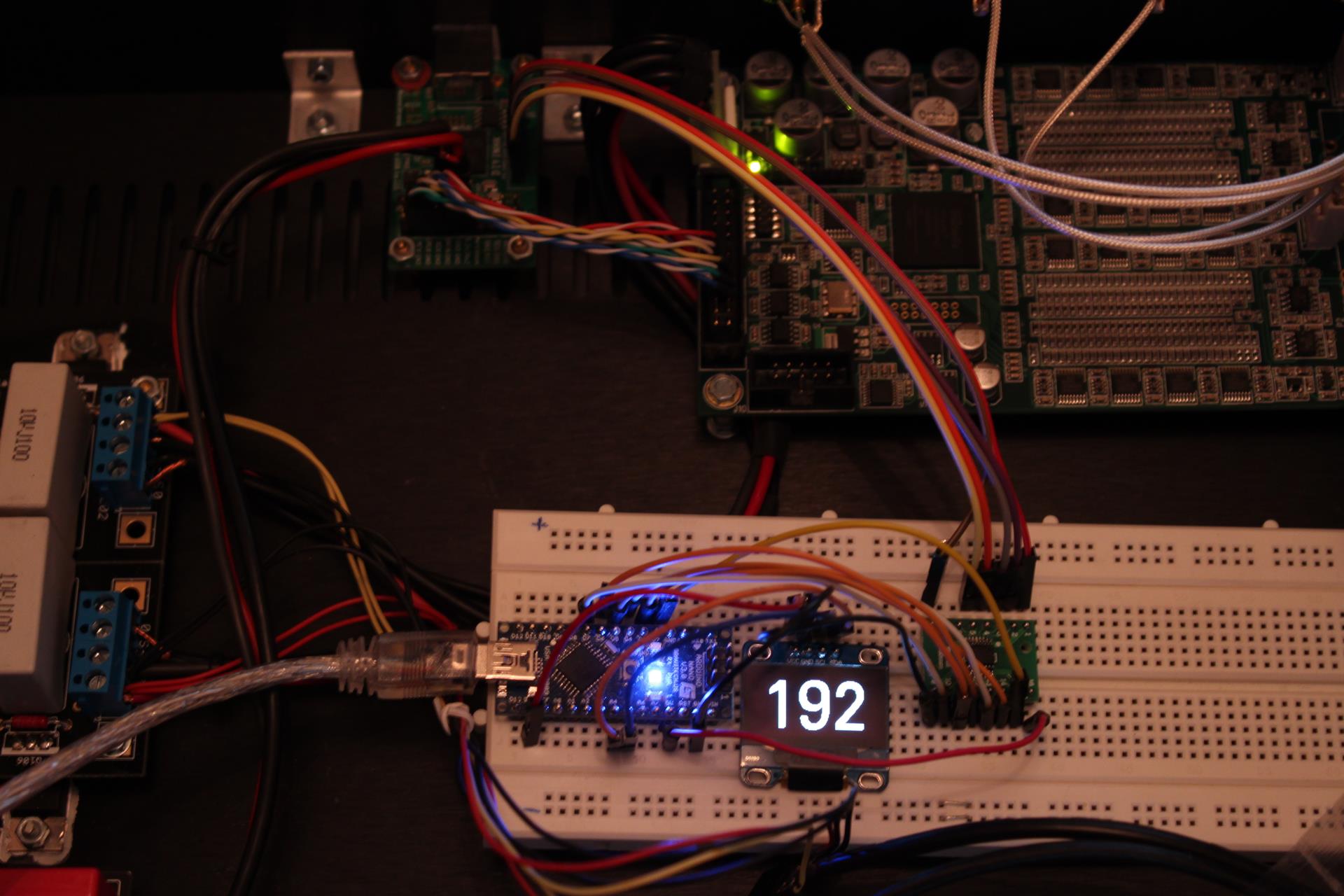
Here is the prototype in action, “reading” the output of a DIYINHK XMOS board in my Soekris DAM1021:
And here is a short video of the prototype in action:
The most current version of the code (v1.37) is here:
This is the change log:
v1.37 08/11/2016:
- Changed once again DSD detection code for Amanero. Now properly supports DSD256/512.
v1.35 16/11/2015:
- Changed DSD detection code for Amanero. Now supports DSD64/128/256/512.
v1.34 26/06/2015:
- Added support for SH1106-based OLED displays.
v1.33 26/06/2015:
- Added code to send any non-recognized IR codes to the serial port.
v1.28 07/06/2015:
- JLsounds code is fully tested and working OK.
v1.24 01/06/2015:
- Remote power on/off implemented.
- JLsounds code is not working! To be fixed soon..
v1.03 29/05/2015:
- Signal type is now displayed (for 3 seconds).
- IR remote control supported for changing sources.
- Source name is displayed (in case of USB for 3 seconds).
v0.36 25/05/2015:
- Updated WaveIO code to also display 352.8K & 384K. It is now fully tested.
- Fixed decimal point display bug.
- Amanero code is fully tested and working OK.
v0.34 26/04/2015:
- First public release.
- Sampling Rate now displayed as float (with decimal point). Slightly smaller font.
v0.33 24/04/2015 :
- Debugged Amanero code. Should be fine now. Still not tested.
v0.32 22/04/2015:
- Added DSD detection for the JLSounds interface (not properly documented, so not sure if it works OK).
- Added support for WaveIO interface (not tested).
v0.3 21/04/2015
- Initial version. Shows only the sampling rate (type INT for now).
- Compatible with 0.96″ OLED display (SSD1306, 128 x 64)
- Compatible with Amanero Combo384 (not tested), DIYINHK XMOS & JLSounds interfaces (not tested).
Nice. Beats the optional diyinhk LEDs.
If the diyinhk isolated USB-i2s XMOS board is used then I assume you don’t need your isolation circuitry? And, the 1,2,3,4 pins you refer to in the diyinhk column are the non-power pins on CN2?
Yes, in case of the isolated DIYINHK the isolator is not crucial, but I would put it in anyway. Keeps the Arduino stuff from messing with the XMOS stuff. Yes, you are right about the pin numbering, with the first pin starting from the side of the GND and 3.3V pins. I’ll put up more info soon.
Works in USBStreamer ?
http://www.minidsp.com/products/usb-audio-interface/usbstreamer
I had a look at USBStreamer’s manual and I don’t see a way to “read” the signal type, so I’m afraid that it would not work.
thanks:)
Hi,
Great stuff. I am trying to build this thing for my amanero. I have downloaded v0.36, but i would like to try the latest version. The problem is that when trying to download I get the message “forbidden”. I can lownload all the other files on this site, but not USB to I2S soft.
Please help!
best, Paal
Hi there Paal,
Thanks for the heads up! I fixed the link. It should be OK now.
Good luck and don’t hesitate to post here of you have any further trouble.
Thanks!
This is exellent. The download works. The test setup worked at once. I have not bought any isolators yet, but even the 3,3volt output from amanero trigged the 5Volt Nano. Switches nice between PCM and DSD 🙂
Is any shields available?
best, Paal
We did design a PCB at avclub.gr.. It’s not strictly a “shield”, a more fitting word would be “motherboard”. I have a few of them left over, PM me for details.
I can confirm it works fine with the isolated diyinhk board. I did the minor code adjustment for an Adafruit ProTrinket 3V I had (doesn’t have pins 2 and 7) and it worked out of the box. Nice work, thanks Dimdim.
Thank you for your feedback on the isolated diyinhk board. 🙂
hi!
i have error uploading because ir library …
Hello,
If the error you are getting is mentioning something like a duplicate library and the code still uploads, you’ll be fine.
Hi DimDim, i’ve read of your great interface, and i would be interested in a few boards, if still available.
Hi there Benedetto, I have a few left. I’ll email you with the details.
Hello DimDim, is it possbile to have at least two boards?
Thank you
Hi there Sergio,
I think I have a few boards. I’ll check and let you know.
Hi, is there any board left? I’d like to buy one or two.
I’m not sure. I’ll have a look later and let you know.
I would like a board, any left?
Yes, there is. I’ll email you about it.
Hello DimDim, anythig has changed with boards? Is there any to buy?
Hi there, I’m afraid not. Too many things to do and not nearly enough time. 🙁
Hello DimDim,
if no boards left to buy, is there any option you guys share the order at “seedstudio” so we can order by ourselves ?
best
Pepe
with gerber files I could have the PCM anywhere else if neccesary.
Thanks
Pepe
Hi there Pepe,
I’ll talk to my co-designer about this.. If we were to give away the gerbers, I would prefer to provide a rev.2 with a couple of bugfixes.
I had a talk with my co-designer, he had a few boards left that he has passed on to me to give out so there is no rush for a rev.2 for the time being.. 🙂
Hi, so how can I get one of this boards? 🙂
Use the “contact me” link and I’ll let you know.. 🙂
I use your code and add mine to control Ak4490 . So it can switch betwen PCM and DSD
Thanks
That’s what’s great about these little projects.. you end up using them for more than what they were designed for. 🙂
Are you running your AK4490 in software mode or hardware?
That was a dumb question on my part.. Obviously in software.. I myself am dabbling with an ak4490 dac these days..
Hi Didiet,
Can describe Your solution? How You control AK4490?
Pingback: DIY-DAC: Display Audio-params->already there->HiFiDuino-TFT.. – ES Sabre-90xx-Rpi
Hello. Thanks for great project. But after compile with newest version I have problem with free space. v1.37 08/11/2016 , 102%, cant compile. With IR function its 120%.
Hi there, I just compiled it with Arduino IDE 1.8.9 (current version) with the libraries that I’ve linked to above. It compiled without errors, taking up 95% of available program space. Are you sure that you’ve selected the right Arduino (Nano)?
First I have mini, then nano and all works. Thanks 🙂
I recently found this while working on my own display. Interesting (and convenient) that I also went with the Arduino Nano and the 1.3″ OLED before I found this blog. When I found it I brought in your latest sketch. It works for me but I found a little bug and am not sure how to go about correcting it as my programming skills leave a lot to be desired.
I am testing using a couple different Amanero XMOS clones. I feed music files using a windows desktop and Foobar2000. I have several test music files that cover the range of PCM and DSD sample rates. When I allow the app to play down thru the files in sequence, the PCM/DSD works correctly on PCM files and when encountering the first DSD file. However when the files subsequent go from one DSD sample rate to another the display drops back to displaying PCM plus the correct DSD sample rate at the start of each file. In this case, I can see the XMOS controller is dropping the PCM/DSD signal false for about 150ms when it switches DSD sample rates. The Nano seems to pick this up as a switch to PCM and that is what is displayed before the change over to displaying the reported (F0-4) sample rate. This occurs on 2 different vendors “Amanero XMOS compatible” controllers. I dont know whether the Nano eventually sees that it is really DSD (true), but it doesnt change the display.
Pingback: New speaker / little experience-report / Volumio at 2.861 / some new ES9038Pro DACS – ES Sabre-90xx-Rpi