
A few years ago I had an encounter with a ladder volume attenuator. I loved hearing the relays clicking away as they dialed-in the desired attenuation.
Ever since then I wanted to design and build one for myself. The years passed, with other more urgent projects taking priority, but I always had this thing stuck in the back of my mind. I was doing my research at a very slow rate. Slow, but steady. I came across a number of ready-made ladder attenuators, such as the RelaiXed2, the one from AMB, Vicol, and others. I also came across some uC source code, but nothing ready-made for an Arduino.
I know what you’re thinking. Why design such a thing from scratch when there are all these designs ready-made out there? The answer is very simple. For the fun of it. 🙂
The basics
A ladder attenuator’s job is to provide various levels of voltage attenuation while keeping either its input or output resistance constant. The number of required steps of attenuation determines the number of relays one will need. With one relay you will have 2 to the power of 1 steps, so 2. With 2 relays you will have 2 to the power of 2 so 4 and so on. Assuming that a reasonable level of attenuation is anything over 90-100db, we come to the next decision, which is the step of attenuation. Common values are 0.5 or 1db. I considered 1db to be too coarse for a preamp, so I chose 0.5db. The final decision is the desired input and output impedances. The input impedance is (obviously) the impedance that will be seen by the source’s output stage. The output impedance is the next stage’s input impedance.
Once you have all these things sorted out in your mind, you have to do the math to calculate the required resistors. Don’t worry, the days of actually doing math are long gone. There are many on-line resistor value calculators out there, as well as Excel spreadsheets, and they all provide the same output values for the components for the same attenuation and impedance characteristics. I went with AMB’s calculator: http://www.amb.org/audio/delta1/
Design considerations
For my first design, I decided to use 8 relays so with 0.5db steps and 255 steps, I would get a total of 127.5dbs of attenuation. That sounded excellent. I also went for 47KΩ of input impedance and about a MEG of output impedance.
After inputting the values in AMB’s calculator, I got these:
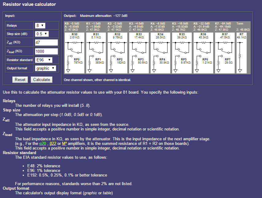
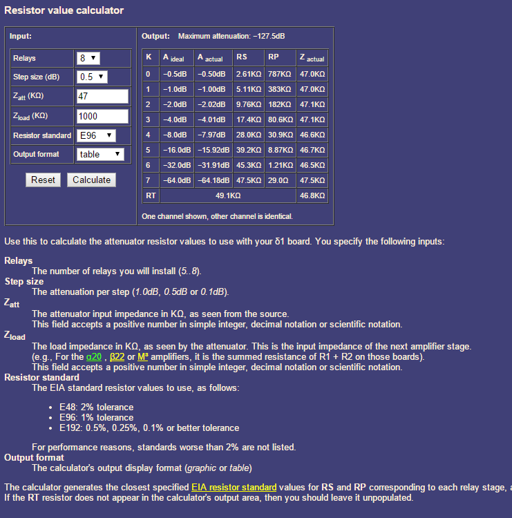
Note that AMB’s RS0 corresponds to my boards’s RAS0 and RBS0 (for the two channels). Same for RP0 (->RAP0, RBP0) and so on.
Circuit design
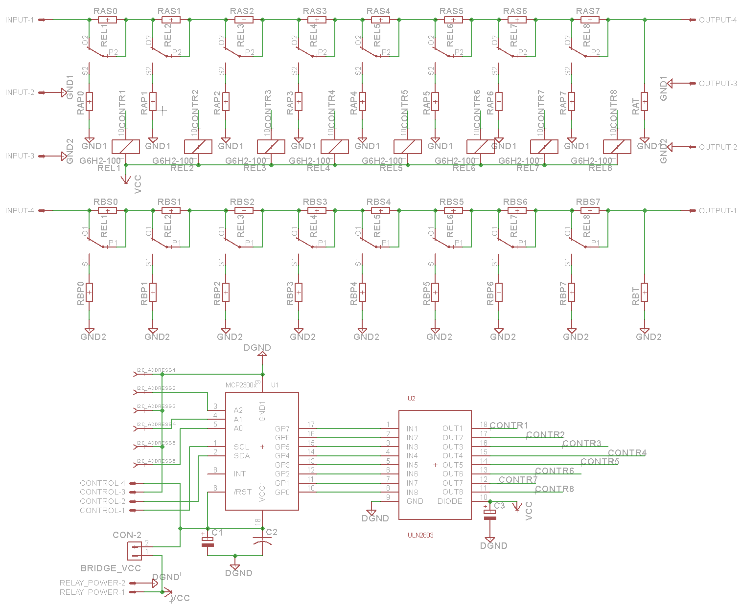
Next up was the circuit design. The actual ladder circuit is pretty standard, there are not many design choices to be made, so I took a look at the relay control circuit. I had 8 relays, so I would go either with a shift register or an I/O expander controlled by I2C. I chose to go with I2C because of the simpler wiring (2-wire bus and software addressing FTW). The obvious choice was an MCP23008.
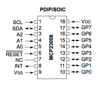
I exposed all of its I2C address selection pins so as to make the design as flexible as possible.
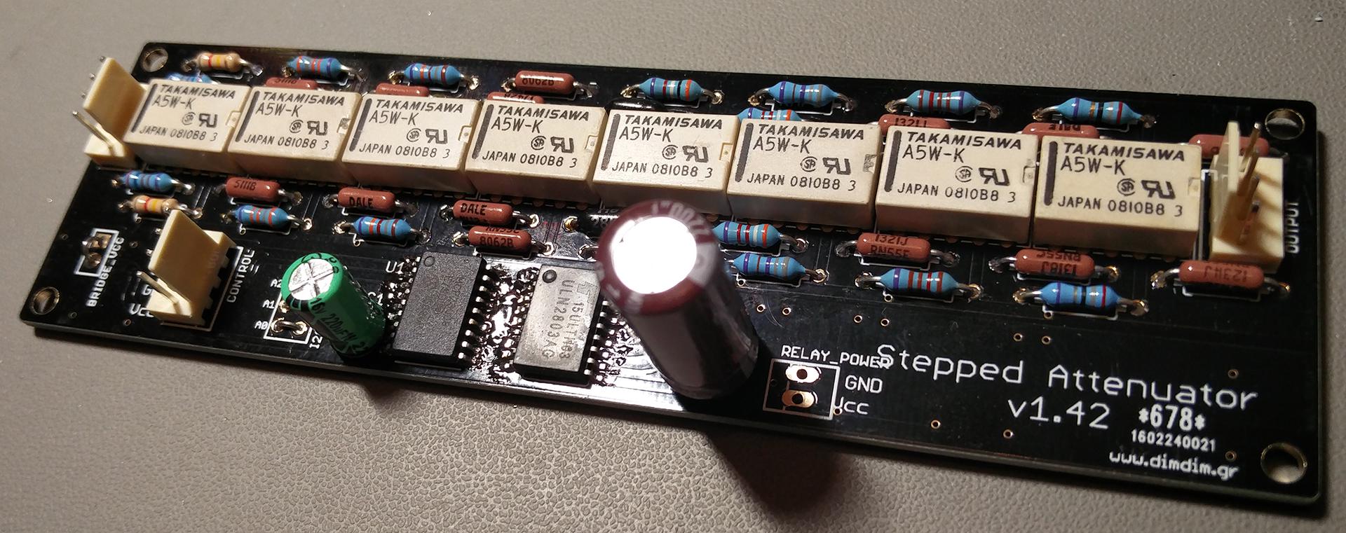
The relays would be 5V, to keep compatibility with the Arduino’s power supply but also to keep electrical switching noise down. To drive the relays I went with another classic, the ULN2803:
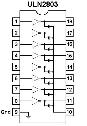
It is capable of supplying up to 500mA of current plus it contains the coil suppression diodes, so it drives the relays directly.
Power to the relays is provided either through the Control header or through the Relay_Power header. If you intend to power them through the Control header, you need to jumper the two Bridge_Vcc pins.
The Relay_Power header adds flexibility to the design, in that 12V relays could be used instead of 5V ones, or perhaps 5V relays with 3.3V Arduino logic.
This is the BoM for the board:
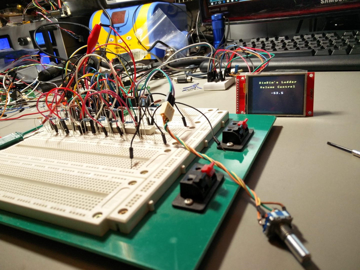
[table “” not found /]I built a prototype on my breadboard, and everything seemed to work as expected:
PCB design
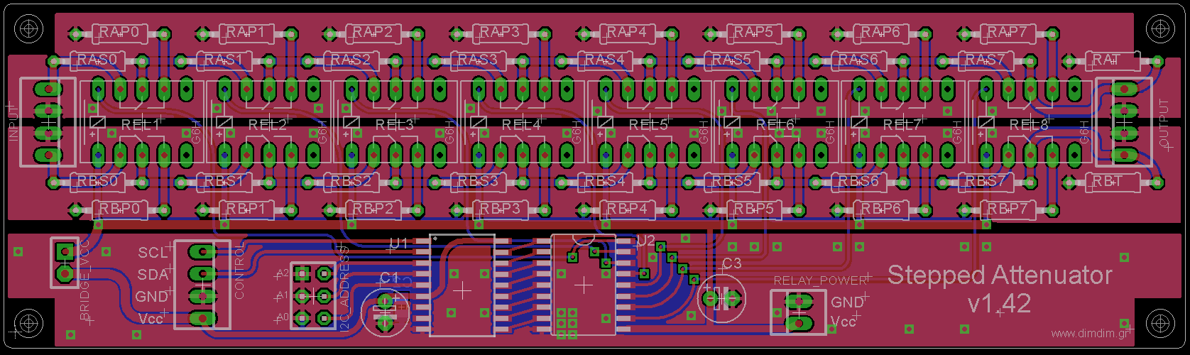
I wanted to go for the most compact PCB possible, so I designed one that was long enough to have just enough space for the relays and input / output headers.
I opted for a design with completely separated channels and ground planes.
The end result was a PCB with a length of 13.6cm and a width of 4cm.
I generated the necessary gerbers and placed an order on http://dangerousprototypes.com/store/pcbs (the experimental branch of http://dirtypcbs.com/).
This is what came back:
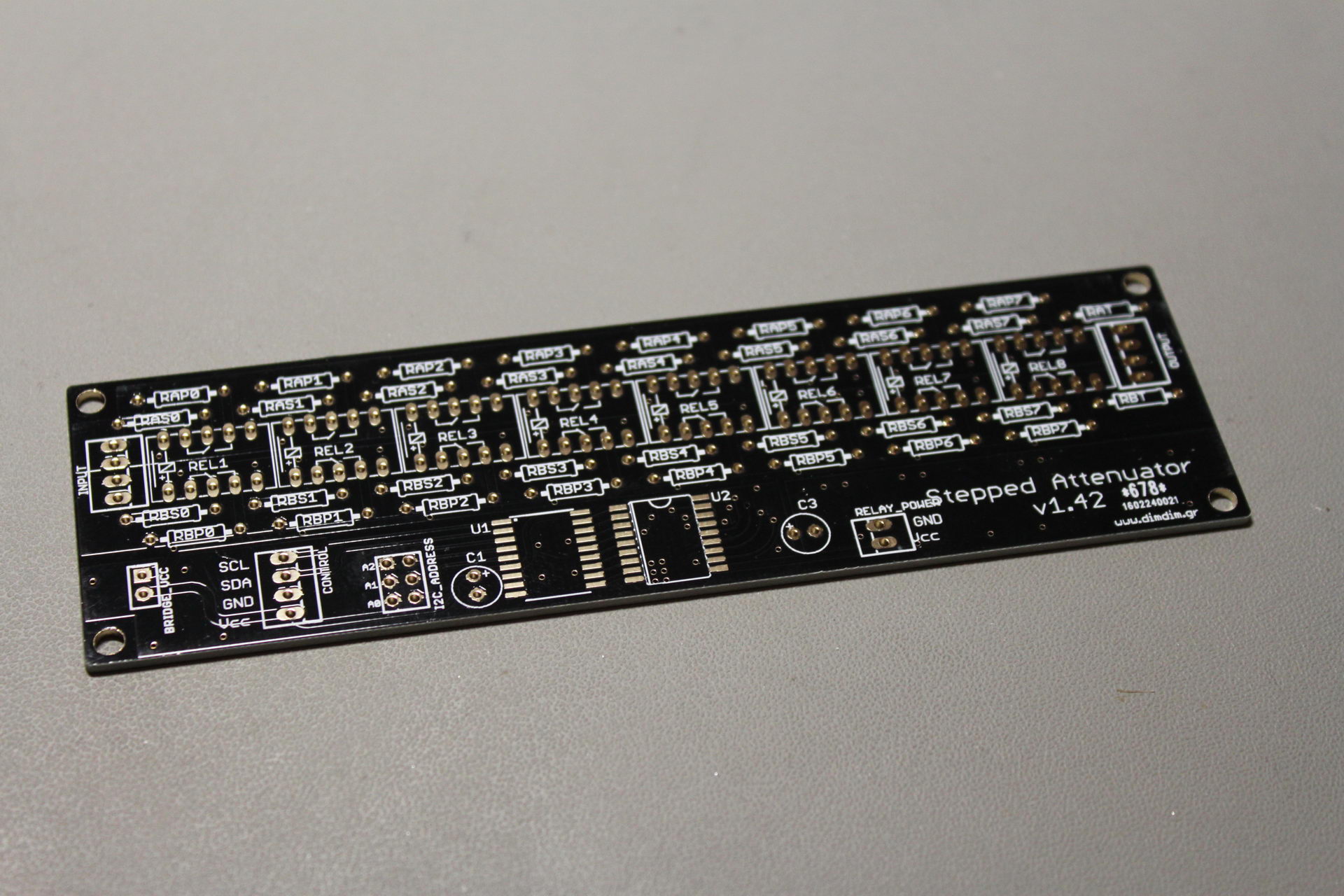
A short while later, it was finished:
I decided to call it La Skala (skala is Greek for ladder).
Arduino Code
I began with a simple algorithm that determined which relays should be open and which closed, depending on the required attenuation. The result was a piece of code that worked, but was causing audible glitches at certain level changes. That was due to the sequence of switching of the relays. For example, when going from -31.5db to -32db, there was an instant in which the relays that were performing the attenuation had switched off but the single relay that would attenuate the signal by 32db had not yet turned on. That created an instant spike in volume. There were several such points during level changing. I solved the problem by using a different sequence of relays, depending on whether I would be increasing or decreasing the attenuation.
Another problem was the spike in power caused by the simultaneous switching of a large number of relays. Each of these relays draws about 25mA of constant current, but the instant they turn on their power draw is quite larger than that. We can have up to 7-8 relays switching at the same time, so the current that is required turns out to be significant. I decided to determine in software the number of relays that would need to change state with each change in attenuation, and when necessary introduce a delay between relay activations. This delay is variable, from 0ms when up to 3 relays change state, up to 50ms (per relay) when 7 relays or more change state. These numbers of microseconds are not magical – I just thought them up and can’t really justify them. Some more experimentation is necessary here. What matters to me is that with this code there are no audible glitches in audio when changing attenuation levels.
One issue is that when using the rotary encoder the relay responsible for the 0.5db attenuation switches on and off with any adjustment to the attenuation. I intend to include code that takes into account the “acceleration” of the turning of the encoder to save unnecessary activation of this relay.
The code is currently at a Beta stage, meaning that it is functional but not complete. Still, it performs the basics:
- Controls the volume via rotary encoder.
- Displays attenuation on TFT display (ILI9341 with SPI) and serial port.
- Outputs attenuation info (plus other details) to serial port.
Currently the code is at v0.52:
Software Requirements:
Basic Hardware Requirements:
- Arduino Uno or better
- TFT with ILI9341 controller, connected through SPI (not really necessary.. it just shows the attenuation)
- Rotary Encoder
Here is the revision history:
v0.52 31/05/2016:
- Bug fixes. Everything seems to be working OK.
- First public release.
- Commented out TFT code to make code fit in an UNO.
v0.44 11/05/2016:
- Added code to take into account the number of relays that switch states, so as to reduce power supply loading due to many relays activating at the same time.
- Attempt to eliminate small glitches occurring at certain steps by implementing different function for increasing & decreasing attenuation.
v0.30 15/02/2016:
- First attempt at coding an appropriate algorithm. It works!
- Outputs status info to serial port and TFT (ILI9341 with SPI).