

Buffalo III (outside)
My latest project is a Twisted Pear Audio Buffalo III DAC.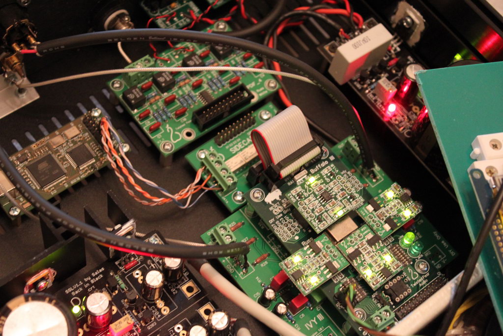
I intend to give a full presentation, but for the time being you’ll have to make do with a few pictures and a series of posts on the various components.
DAC Board
I chose to go with the Twisted Pear Buffalo III board as it was widely regarded as the best VFM and DIY-friendly board around.
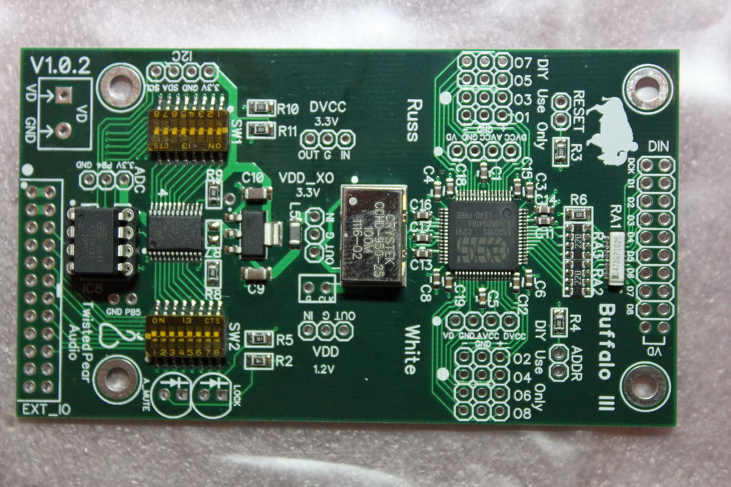
It is based on the ESS Technology Inc.’s ES9018 SABRE32 32-bit 8-Channel Audio DAC. While the board supports 8 channels, it is configured for stereo output (essentially using half of the DACs to drive each of the two channels). The clock is a top of the line Crystek CCHD-950-25 running at 100MHz. Voltage regulation is taken care of by on-board Trident v3 regulators.
Controller
Since the very beginning of the project, I had decided that I would use an Arduino to perform all of the control functions (source selection, volume control, setting of parameters, etc.).
That led to the development of the TFT HiFiDuino Project. More info on that can be found here:
- Code: https://www.dimdim.gr/arduino/tft-hifiduino-code/
- Custom shield: https://www.dimdim.gr/arduino/universal-signal-isolator-shield-for-the-arduino-due/
Power Supplies
It was decided that the DAC would be powered by three Salas BiB v1.1 rev.2 shunt power supplies. The boards and minikits were ordered through the Group Buy at diyaudio.com while the rest of the components were sourced from either Mouser, the local market or Ebay. The power transformer was custom made.
A short while after the GB closed, I received in the mail the Salas BiB board as well as all the necessary minikits:
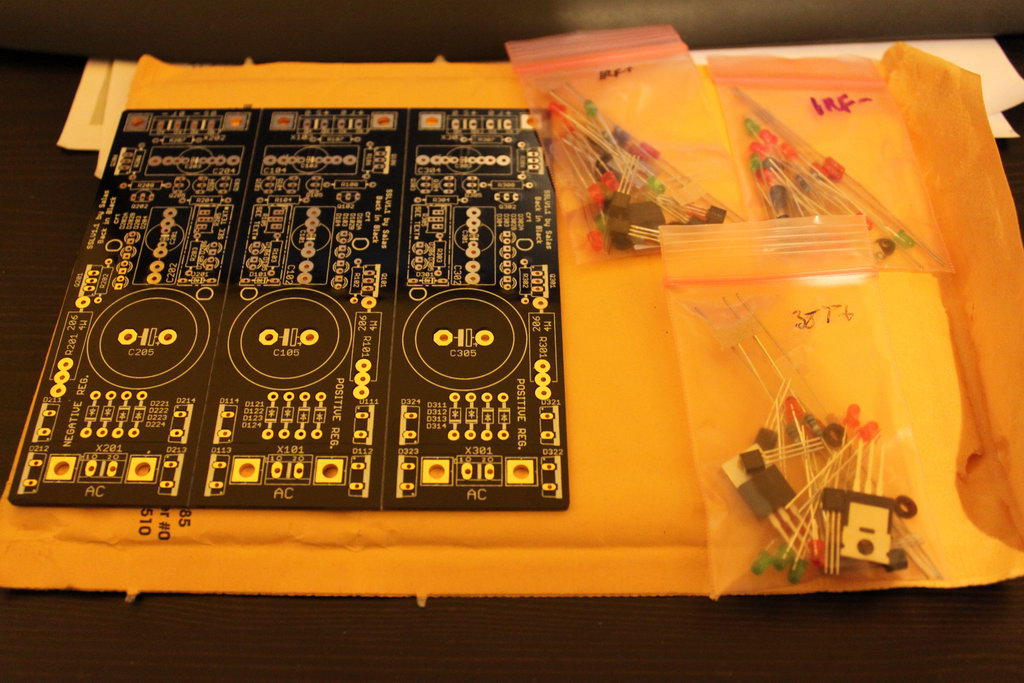
I sourced the rest of the necessary components through Mouser, Ebay, and the local market.
For the +5.25V for the Buffalo board I decided to go with the BJT version of BiB since the MOSFET version sometimes has trouble going that low (a.k.a. it is not recommended by the build guide which is written by Salas – available here, Greek version here). In retrospect, if I were to do it again, I would probably try my luck with the MOSFET version. It is worth a try since it has considerably better characteristics.
This is the BoM I ended up using:
[table “” not found /]This is its output while powering the Buffalo 3 board:
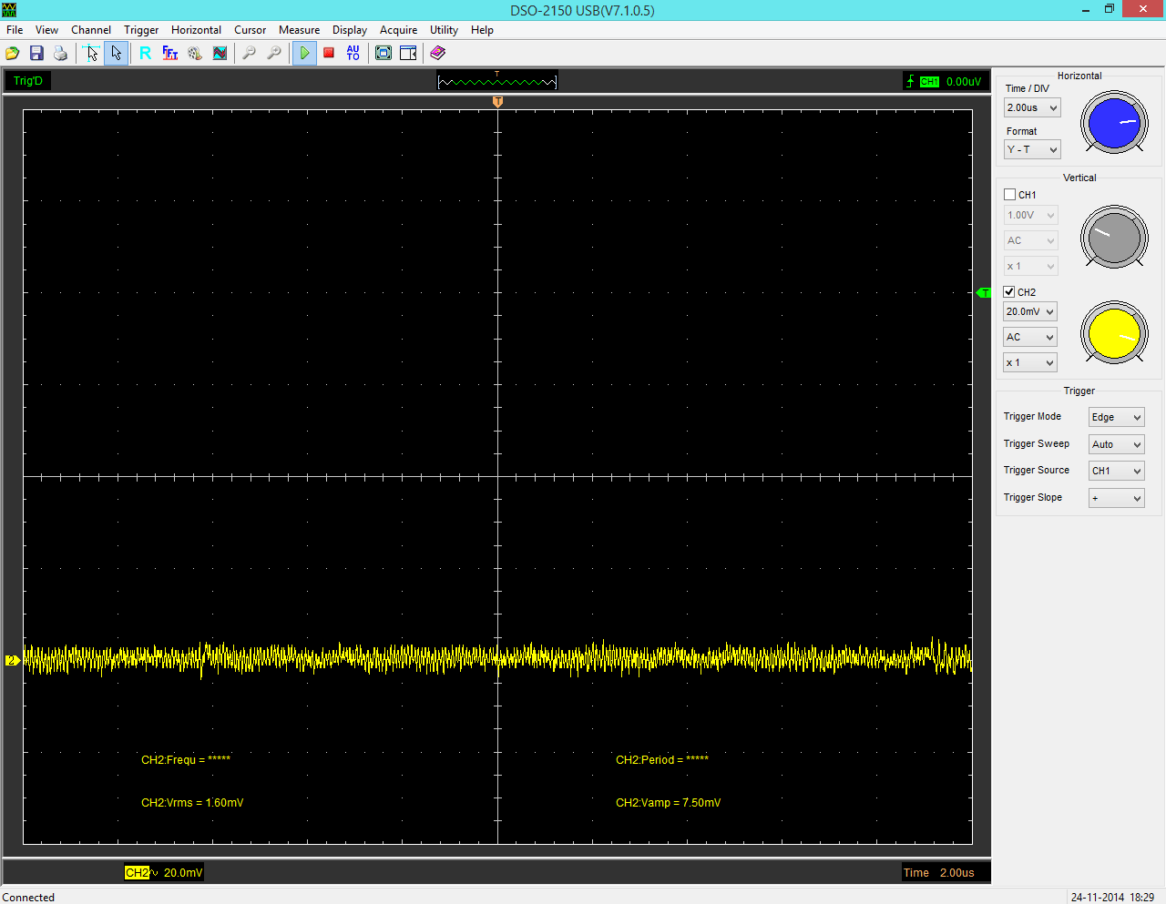
For comparison, this is the TP Placid HD powering the same board:
So the BiB was indeed a good choice.
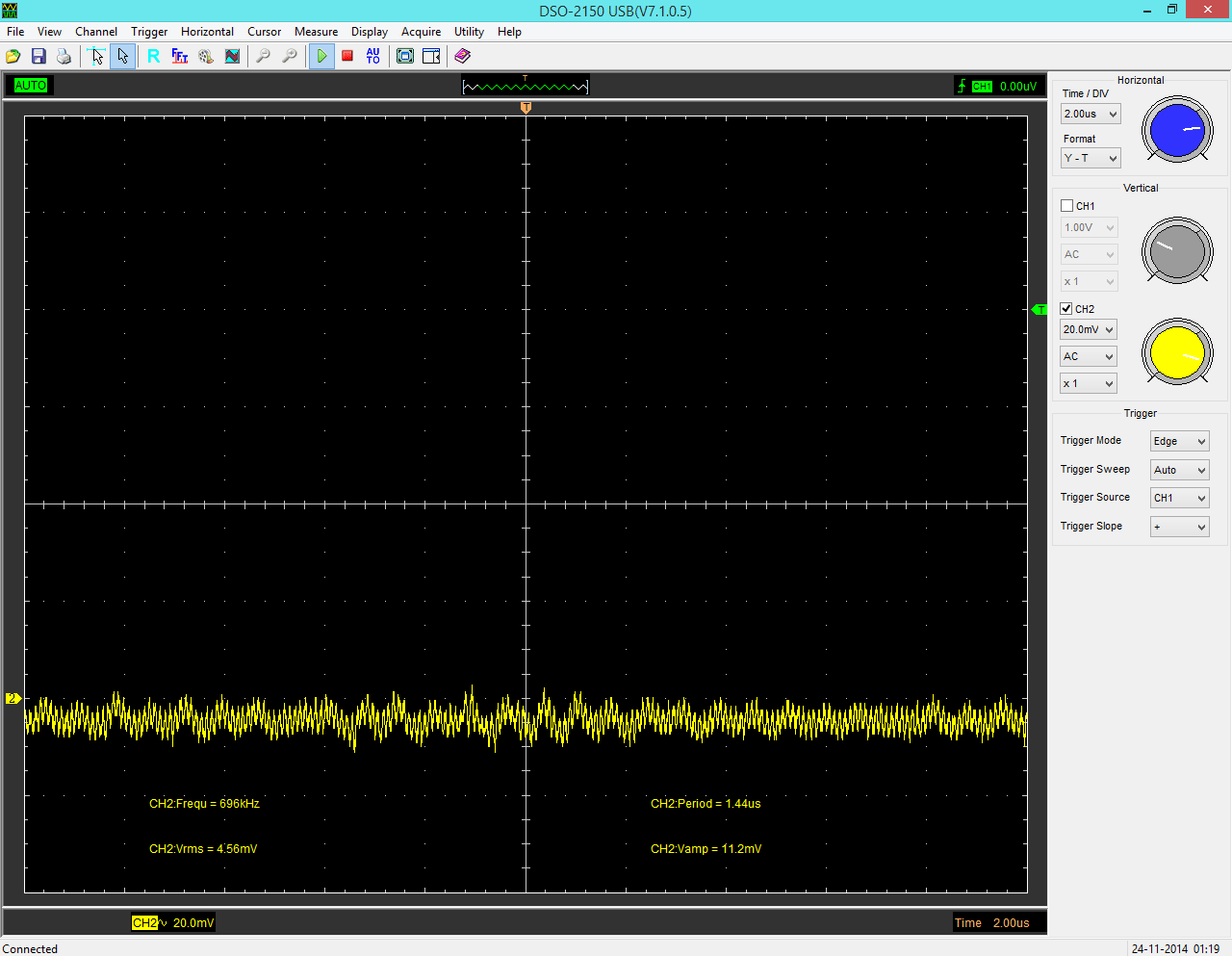
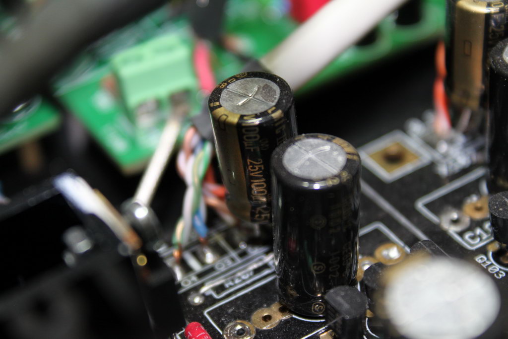
For the +/-15V for the IVY III stage I went with the MOSFET version. I chose to play it safe and go with electrolytic capacitors for both C201/C301 and the Zobel’s C203/C303.
But when I connected it to the IVY III, I realized that I had a problem. I got this:
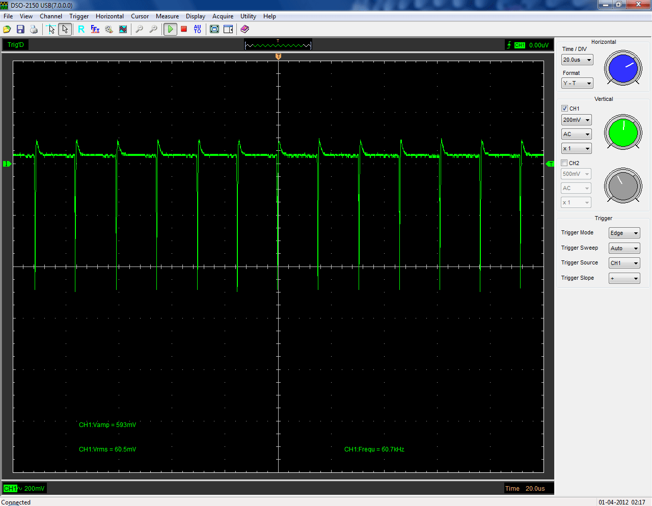
After mentioning the problem to Salas on avclub.gr, and after him taking a look at the IVY III’s schematic and doing some simulation, he concluded that the problem was caused by the local bypass capacitors located on the IVY III. He suggested that I remove them, otherwise insert 1Ω resistors in series with the positive and negative rails on the IVY III board. I proceeded with the resistors, using 1.2Ω metal film ones that I had on hand, and I got this:
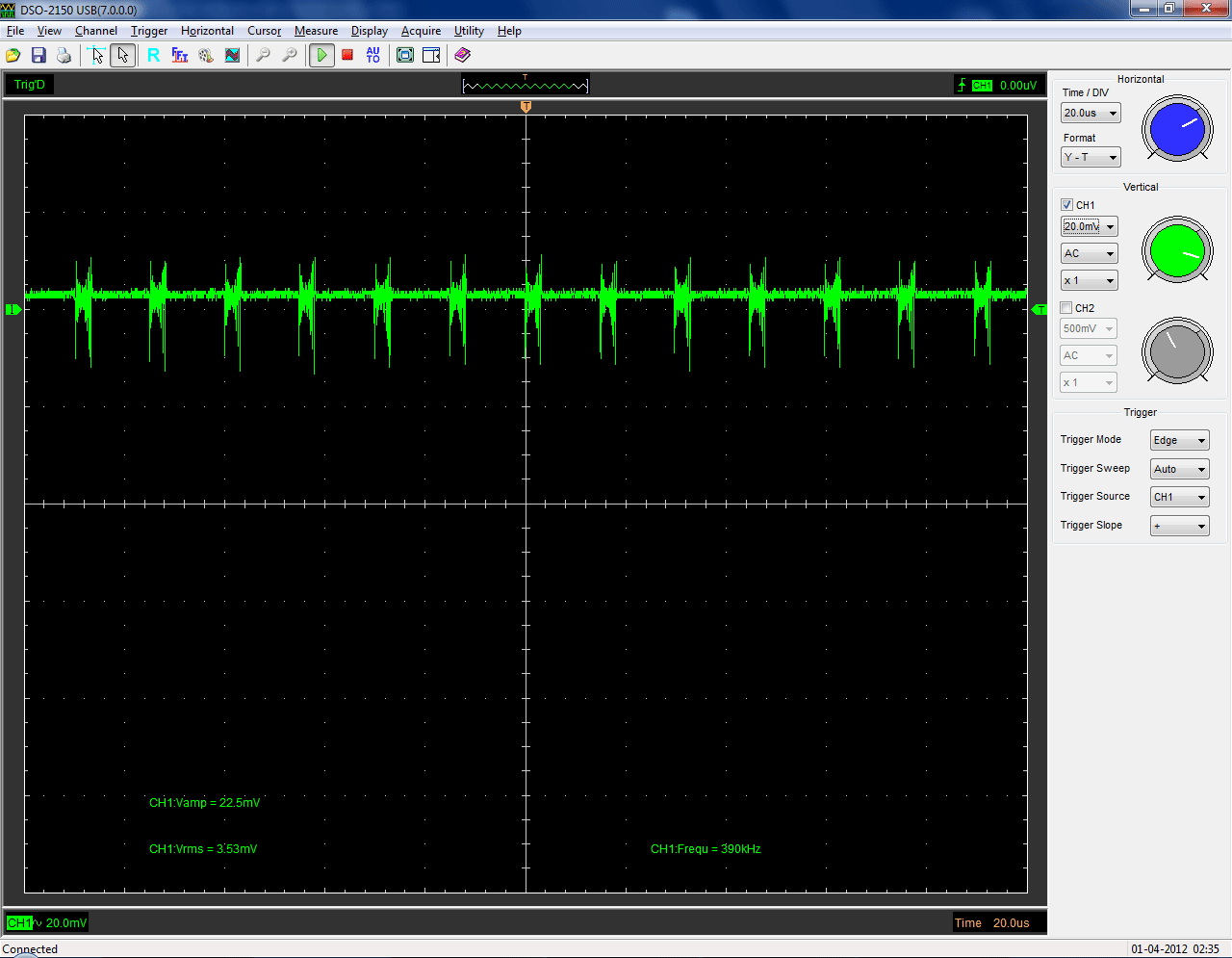
This was clearly an improvement. Salas suggested I connect capacitors across the Sense lines to further filter things out, so after trying out several capacitors (of different capacities as well as cost), I decided that the best results were to be had by using a couple of ELNA Silmic II 100uF ones:
When everything was wired up properly, I ended up getting this:

I was perfectly happy with that, so I called it quits.
The same was done on the negative supply, which was exhibiting similar behaviour the whole time.
After all that, this is the final BoM for the +/-15V power supplies:
[table “” not found /][table “” not found /]
Hi,
Just used your BOM for +- 15V, but somehow don’t get more than 3.75v (using a 5W 20Ohm resistor on F+S)
Any idea what might be the problem?
Hi there,
Using a 20 Ohm resistor you are asking for 750mA from the reg, which it is not designed to do. The IVY III will draw at the most 150mA, so you should use a 100 Ohm resistor as load. If I remember correctly I had chosen to go for a total of ~250mA CCS current.
No plans for designing and building your own IV stage? Still looking for something more affordable, as I would need 4 of them (8channels)
It’s not easy designing a proper I/V stage and I’d be lying if I said that I consider myself qualified to attempt something like that. The thing is, TPA’s IVY is IMHO a VFM choice. It is relatively expensive because it has on-board expensive op-amps and passive components, but I think that cheaper components would definitely compromise its performance. The problem is that you need 4 of them.. If absolute best performance is not a requirement, you could run the 9018 in voltage out mode and use simple output stages.
Do you still sell the custom shield by any chance