
The Soekris DAM1021 directly supports two s/pdif inputs, a coaxial and an optical one. Soren has provided us with a simple schematic to build the necessary circuit:
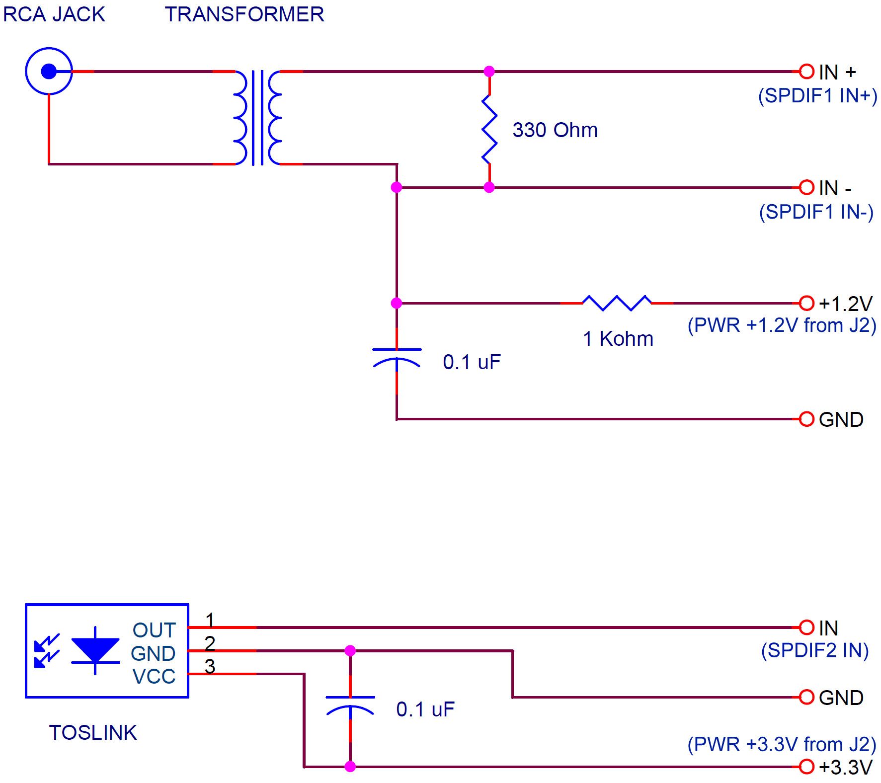
You could very well build this circuit in a breadboard – after all, it is a pretty simple circuit – and you could power it by the DAM’s J2 header, but I opted to do something more elegant and convenient. I designed a circuit board that would accommodate:
- One coaxial s/pdif input, galvanically isolated.
- Two Toslink inputs.
- A mux chip to switch between the Toslink inputs.
- A 1.2V power supply for biasing the coax input.
- A 3.3V power supply for the Toslink inputs and their mux.
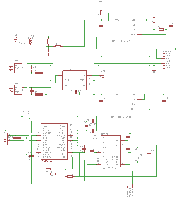
- A USB to RS-232 bridge circuit, to accommodate connecting the DAM to a computer for firmware updates and control.
This is the schematic:
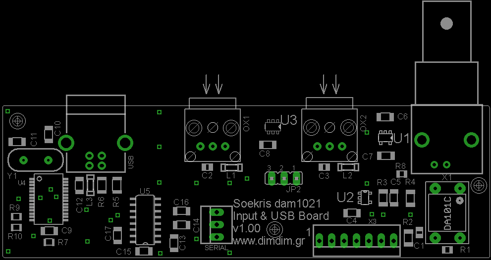
This is the board’s layout:
And this is the BoM:
[table “” not found /]Download schematics & PCBs here: DAM1021 S/PDIF Inputs and USB board (35813 downloads )
I used the old PL-2303HX IC (Rev. A, not Rev. D!) for the USB to serial bridge, since it was the only such chip I could get my hands on when I was designing the board. It is officially supported by most operating systems with the exception of Windows 8 & 10, where it will work, but you might need to do some manual work to install the drivers.
On Windows 8 & 10, the system will find and install drivers by itself, but these drivers will probably not work correctly. Should that happen, the new COM port will have a yellow exclamation mark (as seen on Device Manager). You should download and install these drivers: PL2303 Prolific Driver Installer v1.30 (3464 downloads ) Then go to Device Manager, right click on the problematic COM port and select “Update Driver Software”. Then click “Browse my computer for driver software”, then “Let me pick from a list of device drivers on my computer”. You should see two drivers – one dated 2015 and one 2010. You should pick the one from 2010. That should get your COM port working.
Toslink source selection is by J2, by driving the middle pin HIGH or LOW. LOW means input 1 (OX1), HIGH means input 2 (OX2). You may use a SPDT switch or outside logic (Arduino etc.).
This is the pinout of the main connector (from left (pin 1) to right):
The Serial Port connector is simpler. From top to bottom we have: Serial Out, Serial In, GND
I also designed a set of “helper” boards:
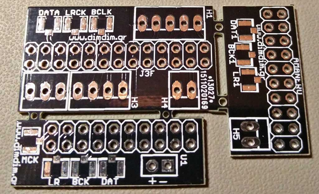
- A board for the DAM’s J3 header, exposing its (currently) useful signals. I2S input is via U.FL sockets.
- A board for the Amanero Combo384. It is very basic, all it does is expose its I2S output and its 3.3V output.
- A board for DIYINHK’s XMOS-based non-isolated board. It is also basic, exposing its I2S output and its 3.3V power supply input.
The most useful one (at least for me) is the one for the J3 header.
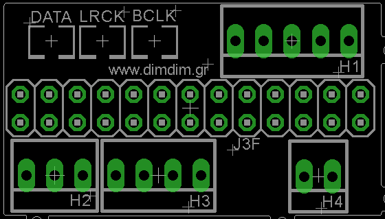
These are its pinouts (pin numbers from left to right):
[table “” not found /][table “” not found /]
[table “” not found /]
[table “” not found /]