
A few months back, a new project appeared on diyaudio.com. It was a DIY R-2R ladder DAC. Its creator, Soren, was clear from the beginning that it was to be a commercial product and if there was enough demand it would make it to production. There was a lot of interest, so it was announced that the green light was given for the board to be mass-produced.
Three different versions were to be made available, the difference being the tolerance of the R-2R resistors. There would be a high-grade version, with 0,01% resistors (dam1021-01), a midrange version (0,02%, dam1021-02), and a basic version (0,05%, dam1021-05).
In theory, different resistor tolerances would mean different amounts of THD. According to the manufacturer, these are the measured performance figures of the three versions:
[table “” not found /]Update (Nov 2015): Soekris has released a Rev 2 of the board, with improved Vref power supplies and a better muting circuit. It is available in just two resistor grades, a 0.01%/0.02% mix and 0.05%.
Update (Feb 2016): Soekris has released a Rev 3 of the board, with further improved Vref power supplies (more capacitance). It is available only with 0.02% resistors.
Update (Jul 2018): I wrote a F.A.Q. for the dam1021: https://www.dimdim.gr/2018/07/soekris-dam1021-frequently-asked-questions-resources/
Being a long-time Delta Sigma DAC guy, I wanted to try a “pure” Sign Magnitude R-2R ladder DAC so I pre-ordered one of the midrange variety. Soon the boards were finished and tested, the firmware too, and shipping began. A week later I received my board.
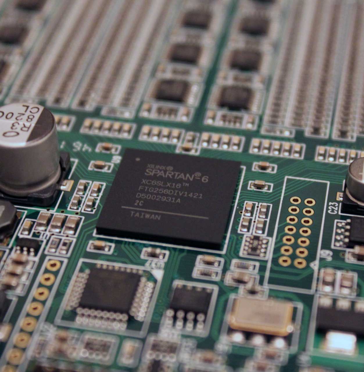
These are the “brains” of the board. The Xilinx Spartan-6 FPGA chip:
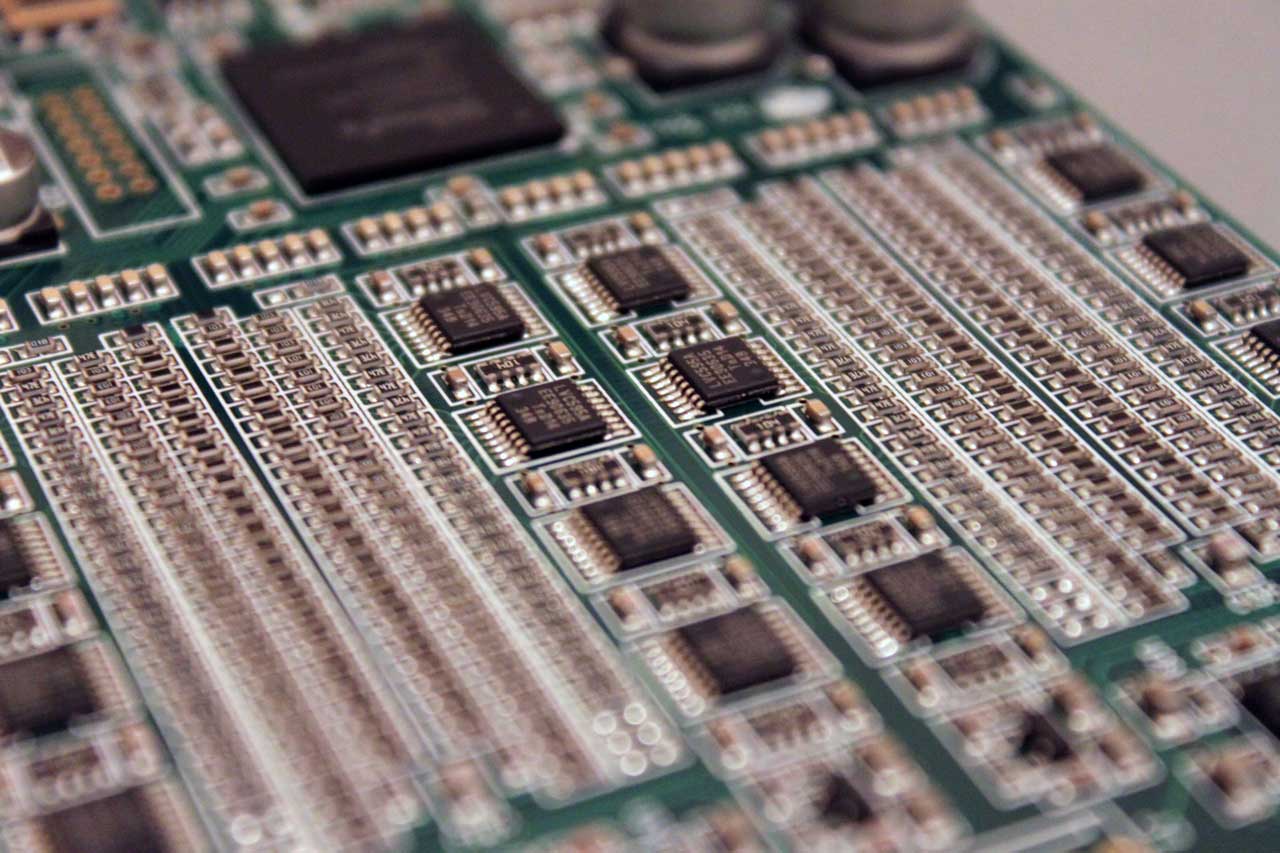
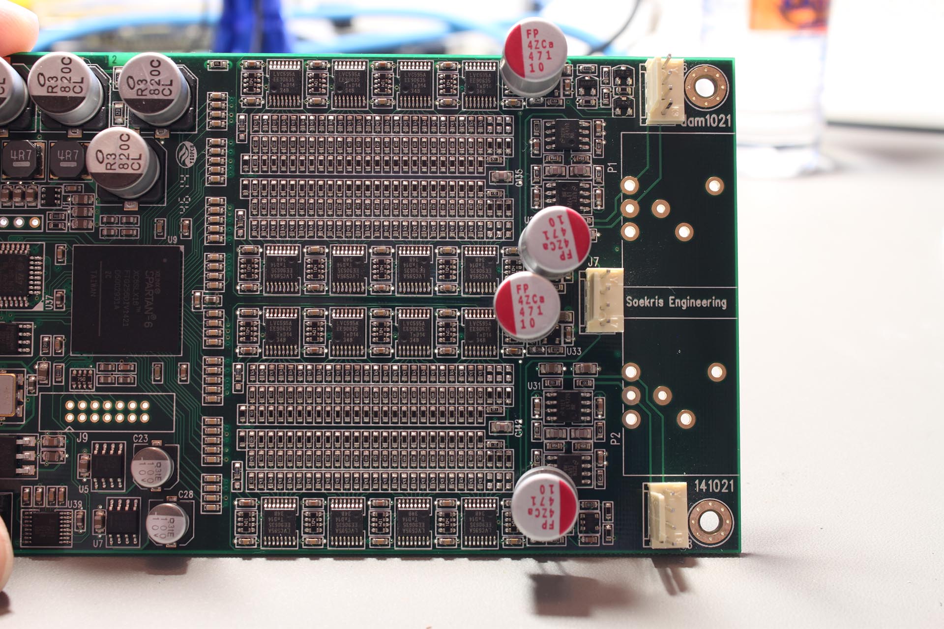
This is the part that actually does the digital-to-analog conversion (well, sort of). The R-2R ladder and accompanying logic:
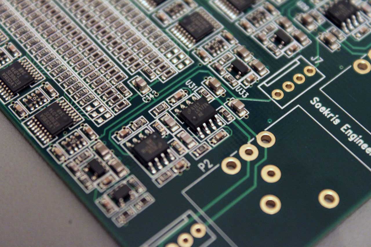
The board has two outputs. A single ended one, taken directly after the R-2R network, with no DC offset and no caps in series with the signal (output at J7 terminal) and a balanced one, using op-amps to convert from SE to balanced (terminals J6 & J8). The single ended output is at 1.4V RMS with a Zout of 625Ω, while the balanced output is at 4.0V RMS with a Zout of 20Ω.
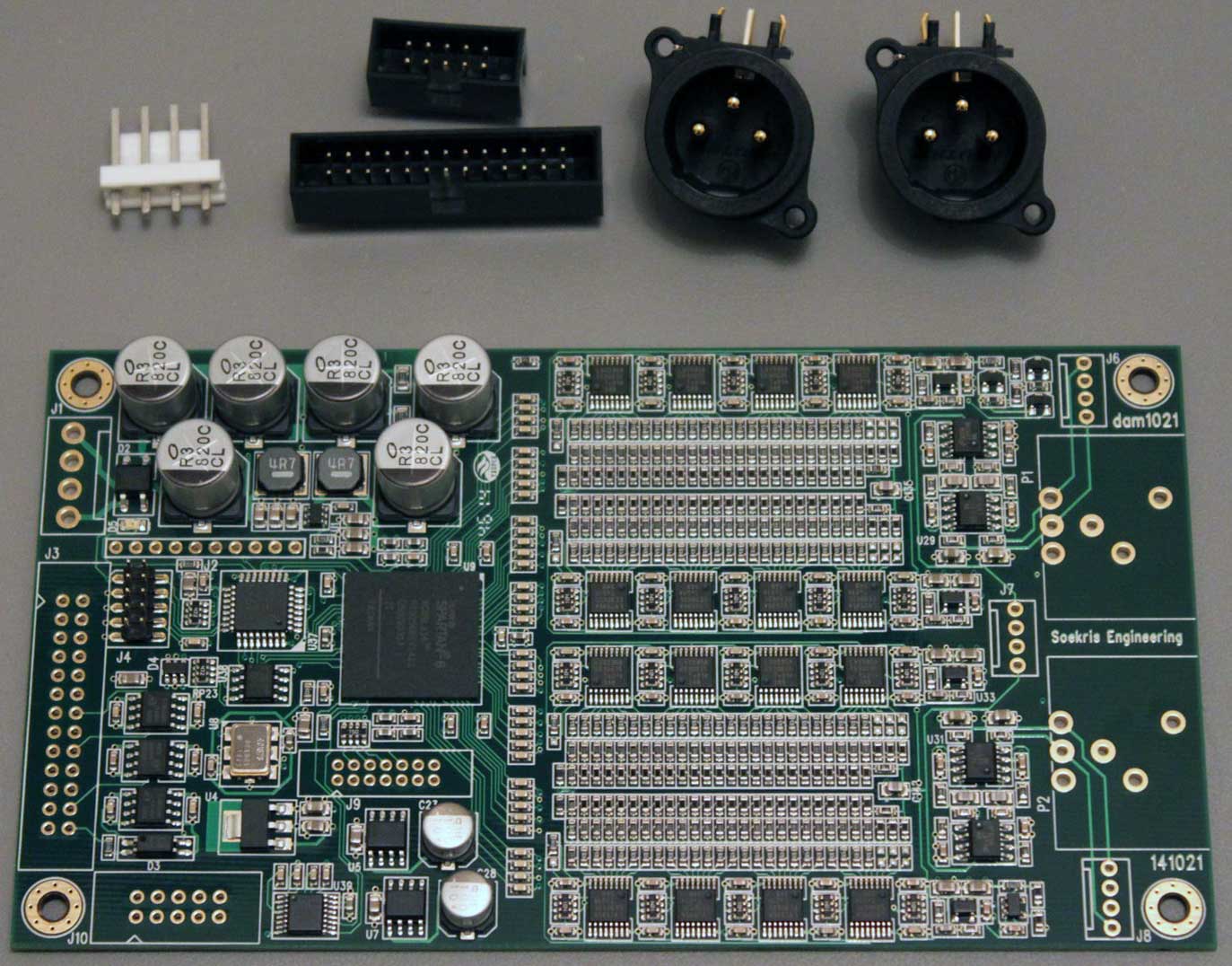
Soren has supplied a mechanical drawing of the board, detailing the various headers:

This board is very simple to set up. What you need (at the very least) is power, a digital source, and some sort of output terminals. If you run a balanced setup, Soekris has you covered since they supply a pair of PCB mount Neutrik XLR connectors.
Regarding power, you need a transformer with two secondaries at 7 to 8 volts AC. The transformer should have a rating of at least 5VA.
You may also use a DC power supply with an output of +/-7.5 to +/-15 Volts. It’s a good idea to run it at +/-12V so as to not stress the on-board capacitors and LDOs. I am currently powering it with a Salas BiB bipolar supply (more details later on) with very good (audible) results.
When it comes to source handling, the DAC has three inputs:
1) I2S (electrically isolated)
2) Balanced for coaxial s/pdif
3) TTL for a Toslink receiver
They are located on the J3 connector:
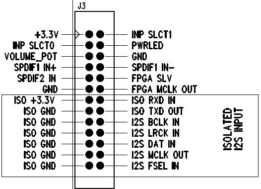
The I2S input is electrically isolated, so you should provide it with 3.3VDC of isolated power. This power may be supplied by your USB to I2S interface (like an Amanero) or any other power supply, as long as it is isolated from the dam1021’s power supplies. This means a second transformer (or a third secondary winding of the main transformer) and the necessary components for rectification, filtering, regulation, etc.
The board features either automatic input selection (with signal detection) or manual selection.
To use manual selection you either use the “INP SLCT0” and “INP SLCT1” pins on J3 or issue commands through the serial port.
[table “” not found /]
N-C means “No Connection”, a.k.a. “floating”
Soren has also provided a schematic for the s/pdif inputs:
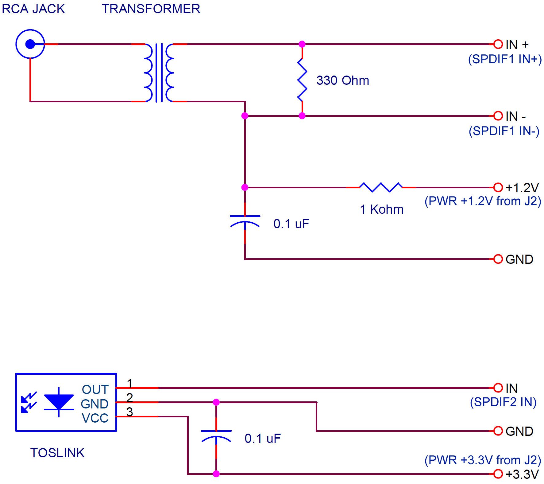
I added a few notes of my own for reference.
It is a pretty simple circuit. Regarding the coax s/pdif connection, you will need a pulse transformer for isolation (the Murata DA101C is a good choice, being readily available and reasonably priced) and a few passive components. You will notice that the circuit requires +1.2V. That is necessary in order to bias the FPGA’s LVDS input pins. You can get that voltage from J2, although I would prefer to use a separate power supply, since the 1.2V on J2 are supplied by a switch mode regulator.
Hooking up a Toslink s/pdif receiver is even easier, since all you need is the actual receiver (I recommend the Toshiba TORX147) plus a 0.1μF capacitor.
I started out with building the above circuit on a perfboard, but ended up designing a custom PCB that supports:
- One coaxial s/pdif input, galvanically isolated.
- Two Toslink inputs.
- A mux chip to switch between the Toslink inputs.
- A 1.2V power supply for biasing the coax input.
- A 3.3V power supply for the Toslink inputs and their mux.
- A USB to RS-232 bridge circuit, to accommodate connecting the DAM to a computer for firmware updates and control.
You can read more about it in its own page.
The board has a serial port for firmware upgrades and control. It is located on J10 (non-isolated) and J3 (isolated). If you intend to use the isolated port, you will need to supply 3.3V to the “ISO +3.3V” pin of J3. Also note that the isolated port became enabled with the v0.99 of the firmware.
Regarding volume control, it may be controlled by connecting a 10K pot to the relevant pins on J3 (left pin to GND, middle to VOLUME_POT, right pin to +3.3V). Alternatively, the volume can be controlled via commands sent through the serial port.
I made a post detailing the firmware update procedure. You may find it here.
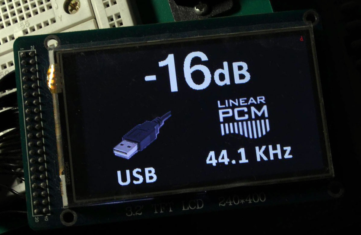
I also made a little video demonstrating how the board handles switching between different sampling rates, both with 0.8 and 0.9 firmware. You can see what the serial console outputs while the changes are being made.
Be sure to watch it in full screen and at 1080p in order to make out the text.
I tested with sampling rates up to 352.8KHz.
Playback chain is Windows Laptop -> Amanero -> DAM1021 -> SE output to preamp.
Following the introduction of the DAC, a number of mainly minor bugs had appeared and also a number of new features had been requested by the DIY community. Almost all of the requests have been fulfilled by Soren, the creator of the DAC, with the release of the v0.99 firmware.
One of the more important enhancements of the new firmware is the locking speed. The dam now locks much faster to incoming signals, so fast that it’s near instantaneous:
The new firmware also allows up to 4 reconstruction filters to be loaded at the same time and to be switched on-the-fly by commands sent through the serial port. The person responsible for making most of the better filters may have left diyaudio.com but he has started a blog filled with very interesting info on filters, mods, etc. At the moment (23/08/2015) the SOTA filter is this one: http://www.moredamfilters.info/node/24
More details regarding the bug fixes and enhancement brought on by the v0.99 firmware can be found here: https://www.dimdim.gr/2015/08/soekris-dam1021-first-major-firmware-update/
Since the new firmware fixed the communication problems that I had with my Arduino, I resumed work on the ArDAM1021 project and have released a fully functional piece of code. Among other things, it supports switching between the 4 filters via remote control.
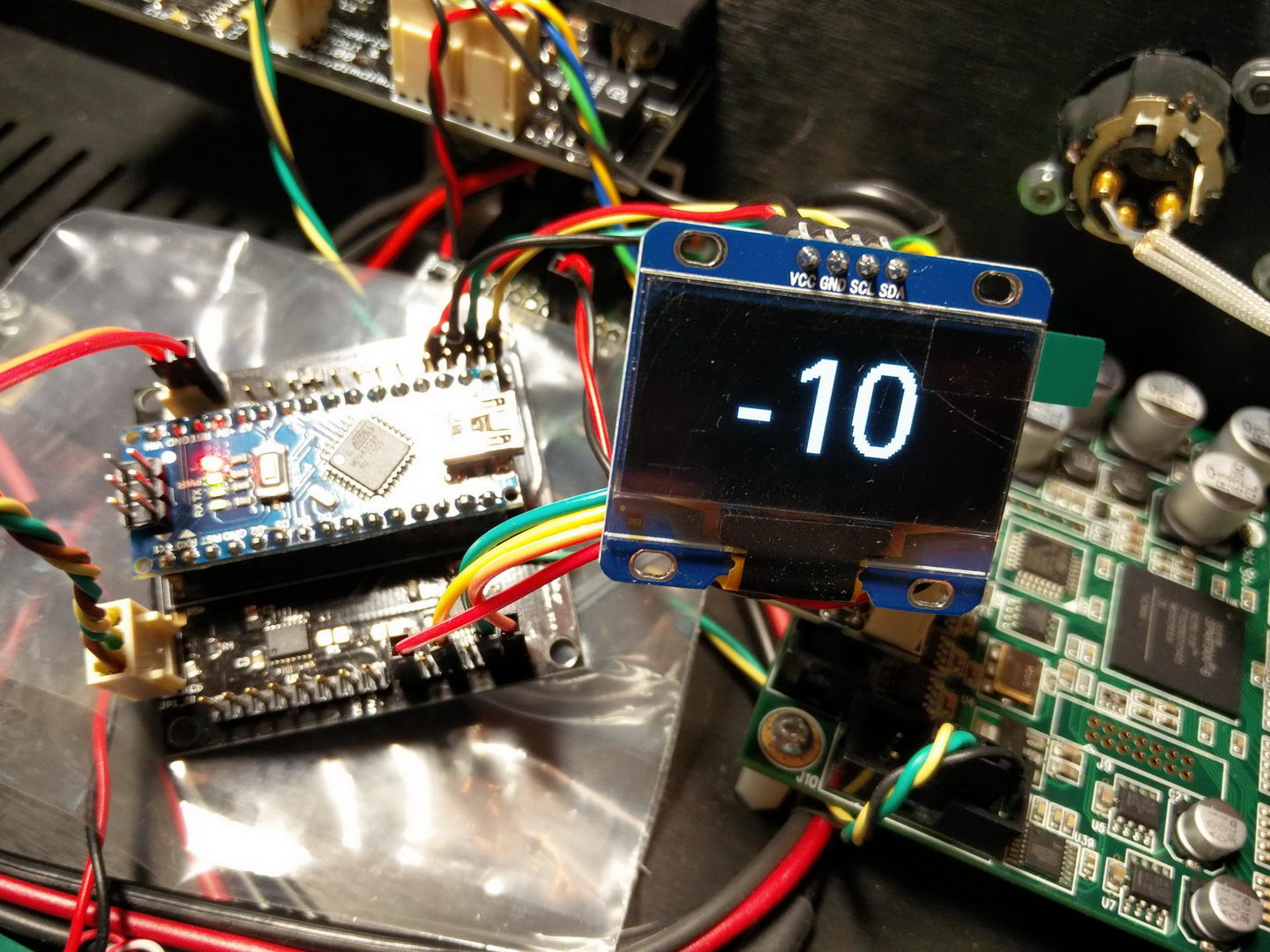
I have also implemented a “lite” version of the code, which runs on more compact hardware (an Arduino Nano) and uses a small 0.96-1.3″ OLED screen.
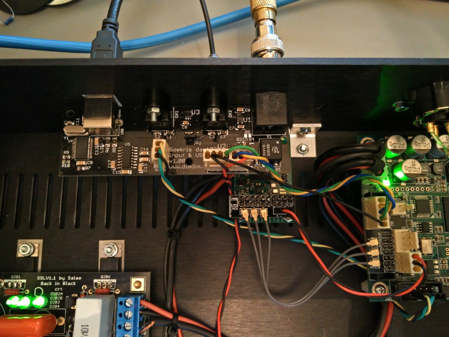
I have installed my dam1021 in a Slimline 2U case from modushop.biz:
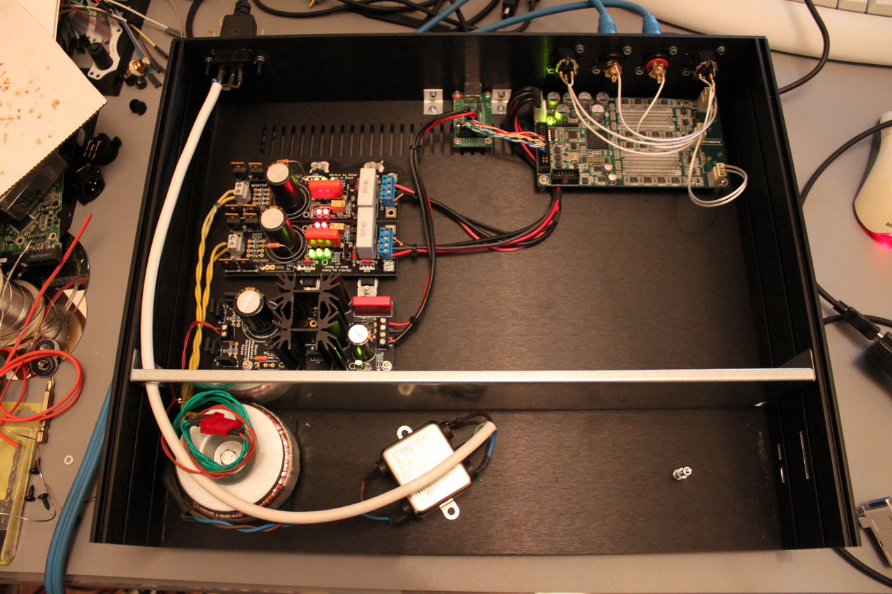
I am now using a bipolar Salas BiB at +/-12V as a power supply for the dam and a Salas Reflektor-D as a power supply for the DIYINHK XMOS USB interface that I am using.
This is the BoM for the +/-12V power supplies:
[table “” not found /][table “” not found /]
I decided to go for about 70mA of excess current on the positive supply and a bit more on the negative.
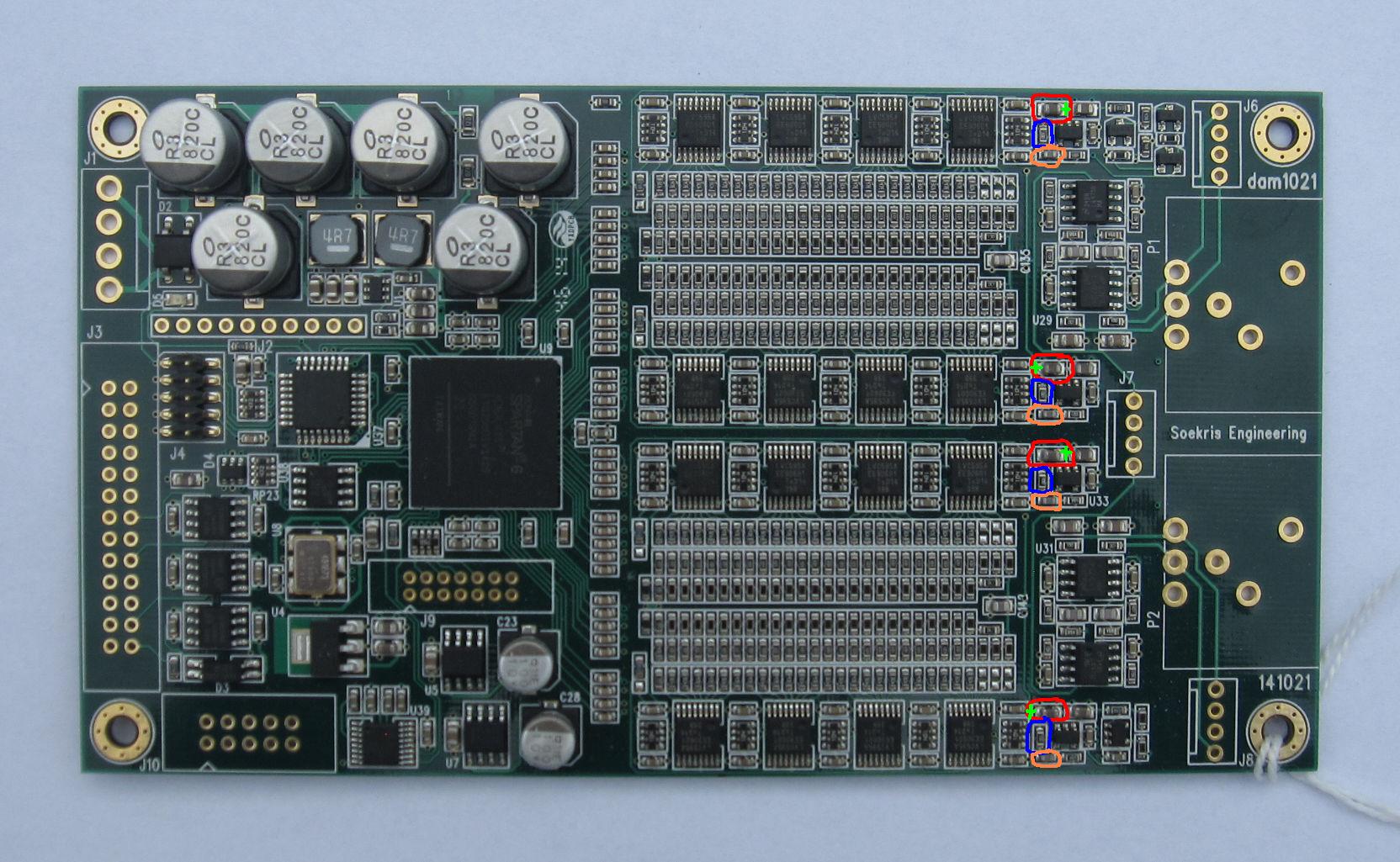
Following an interesting discussion on Vref voltage ripple, on July 17 Soren posted his official “Vref mod” for the dam1021: http://www.diyaudio.com/forums/vendors-bazaar/259488-reference-dac-module-discrete-r-2r-sign-magnitude-24-bit-384-khz-311.html#post4392832
He is suggesting that a number of resistors and capacitors be “piggybacked” by extra components, in order to improve the ripple of the Vref buffer. In fact the new batch of dam1021 boards (Rev. 2) have this mod built-in. Note that the proposed 47uF X5R capacitors are actually 0805 and not 0603. These are the parts that need improvement:
I implemented a slightly different version of the mod on my Soekris. You can read all about it here: https://www.dimdim.gr/2015/09/soekris-dam1021-vref-mod/
I will update this page as I make progress in the build.
THANKS for taking the time to do this.
This is a great service.
Thank you for your kind words. 🙂
Look forward to seeing the Arduino implementation for controlling the DAC. Have not done the TFT version but I do have a slightly modified (ported to an Adafruit Pro Trinket 3.3V and with remote backlight control) 20×4 Hifiduino ESS9018K2M. Been contemplating your TFT – maybe now that I have Soren’s 02 this will be the push I need….;-)
The Arduino code for the Soekris is coming along just fine.. it’s just that coding requires concentration and that is hard to come by these days. But it will be released pretty soon!
Great! Have a drink and concentrate!!
Any chance of a version that uses the 20×4? So as to make it easy for us folks with an existing 20×4 to do a simple conversion.
Have a second drink and let us know……
I’m sorry, but I don’t even have a 20×4 display available.. Still, It would be pretty easy for someone with even basic Arduino coding skills to mash-up HiFiDuino’s 9018 code and my code to control the Soekris.
I will take a shot when you make your code available. Are you also considering a PCB for the Soekris?
@ Derek: If you mean an Arduino Shield, yes, definitely. I’m actually considering a universal shield, good for both Buffalo (I2C) and Soekris (serial) boards.
Yes, sorry, meant a shield for EEPROM etc. That’s good to hear, a shield. Still using the Due, correct?
How feasible is it to port your code to accommodate an implementation without the display? Was thinking of volume control via Apple Remote control, USB/SPDIF selection ( only one SPDIF if necessary) using an Uno/Uno clone. If it can be done avoiding the use of pins 2 & 7 so much the better as my ProTrinket does not make those two pins available to the user.
Sorry for the late reply, it seems somehow I missed your comment!
Yes, I am still using the Due. The code can be reduced in size so that it could fit in a 328, but we would be talking (in essence) about a different controller. The code does not require the use of specific pins, since it does not use interrupts or anything alse pin-specific (besides the Serial port of course). The IR library takes some considerable space, but considering the small footprint of the rest of the code you would probably be all right.
Hi Dimdim,
I left a post on the DIYaudio “Soekris’s DAC implementations” thread. I was curious if you could comment on the differences between your transformer power and the BiB regulated DC power. Others seem interested. Please comment, either on the thread or here.
Thanks
Jac (lehmanhill)
Hi there Jac, I saw the replies on diyaudio.com and was going to comment, it’s just that I haven’t had the chance to really listen to the DAC with the new PS, especially in an A-B comparison since I’ve been sick the past week and a half. I do however intend to do a proper comparison when I regain proper hearing from both of my ears (clogged sinuses are a real pain..).
Hello again! I have done some listening tests and posted my impressions on diyaudio.com as well as here: http://www.dimdim.gr/2015/03/soekris-r-2r-sound-impressions-with-salas-bib-ps-alpha20-line-stage/
I hope you are feeling better.
I’ve got a noob question about your BiB configuration.
I try to “reverse” your salas calculator for your build to build the same.
Here I my guess: You use a 12v transformer, You did not use pre-filter, and you setuped à 350ma cc (that’s the only value I get 4.2ohm resistor in R101 configuration with your given LED Bom) ?
The positive rail is given for 180ma, with 350-70ma that’s for a 280ma load.
Where did I go wrong ?
Thanks for your contribution 🙂
I’m assuming that you are using Salas’ SSLV1.1 Calculator V1a.xls. In this xls, the Vfs for the D102, D103, D104 are by default 2.1V. That is not true for my green LEDs, which have a (measured) Vf of ~1.9V. If you put that in the calculator you will see that the numbers do work out for my BoM. I used the LEDs that came in TeaBag’s minikit, so if you have the same LEDs and you measure their Vf you should get the same number I did, ~1.9V.
A Great tutorial, I have made the DAC ready using my local PSU with a RCORE transformer of rating 12-0-12V 1A rails. But want to improve the power supply section as I was very impressed with this DAC, hence sourced a pair of Salas BiB (-IRF/+IRF) and a Salas Ref-D. Now I am in search for a transformer for the DAC requirements. Currently I am using the Amanero I2S converter which gets powered via USB, but also have a diyinhk’s XMOS based I2S converter which needs external 3.3V power supply. Little confused which voltage/current ratings based RCORE transformer should I be going for the Salas power supplies. I am freezed on the 12V+9V ones which the Salas’s require but not sure of the current ratings that I need to choose. Also currently I am using a centre tapped RCORE (12-0-12) but the Salas needs dual 12,0 and 12,0 for BiB’s and 9,0 for the Ref-D. I would be preferring to go with RCORE rather than toroidal transformer. Please suggest the optimal one that I need to go for.
Thanks
Salas suggests that the input to the BiBs be about 5-7VDC above the expected output voltage. With that in mind, you will need a transformer with two secondaries, each of them giving you about 14VAC. Since that would mean a custom built transofrmer, you will be fine with run-of-the-mill 2 x 15VAC. A 12VAC transformer will not do, as it will give you only ~15.5VDC before regulation. Regarding the current, you should be more than OK with a 30VA unit. Regarding the Ref-D, you do not really need a 9VAC transformer for 3.3VDC output. You should be OK with a 6VAC secondary. 9VAC would not be a big problem, it would just mean more radiated (wasted) heat. The current output should be >500mA, so for 9VAC we would be talking about a 5-10VA unit.
Thanks for the clarifications. Can you please post the links where I can get the rated transformers (that you pointed out with the figures) specifically RCORE as I am more interested in them rather than Toroidal. Also I would like to have a single RCORE transformer for both the BiB’s and Ref-D rather than going for different transformers as space is a constraint in my cabinet.
I don’t have much experience with R-Core transformers, I have bought only 1 such transformer and am yet to use it in a project (Chinese one, I got it off of Ebay). I did a quick search and found one such transformer that should suit you just fine: http://www.ebay.com/itm/0-115V-230V-50W-R-core-Transformer-X-Former-15V-15V-9V-9V-/120884233842?hash=item1c25430672:g:1ekAAOSwaNBUbhur Please note that I can not comment on the quality of this transformer, just that its voltage and current outputs are OK for your case. You will also get a spare 9VAC secondary – it might come in handy in the future (Hint: to power a s/pdif input board).
Thank you will look into the same.
Based on similar specifications I am trying to source it within my country. But wanted to check like will their be any sound difference between a Toroidal and RCORE transformers especially for DACs. As I am currently using couple of RCORE for both of my builds (preamp + DAC) and never heard a Toroidal in my setup except may be a power amplifier. As sourcing a Toroidal is easier than RCORE with the required specifications.
The D121,122,123,124,221,222,223,224 are diodes and as per your BOM it refers to MUR860 which is the same as per the Salas BiB manual as well. But if you look at the picture that you posted of your build those looks like resistors or different types of Diodes. Please clarify as I can see that these are the matching ones from element14 site that I have booked.
http://in.element14.com/multicomp/mur860/diode-ultra-fast-8a-600v-to-220ac/dp/1625180
If you are referring to the diodes seen on this pic: http://www.dimdim.gr/wp-content/uploads/2015/03/IMG_9263_resize.jpg I’m pretty sure that they are MUR860.. To me they look the same as the ones in your link. Are we looking at the same picture?
Yes I was referring to the same picture. In fact I felt like they were looking more of a resistors in orange color 🙂 hence got a doubt. Thanks for the clarification.
If you can post a high resolution close up picture it would help me in building mine.
Thanks.
Sure thing, I’ll post one later today.
Thanks, now I still getting doubt regarding the components D121,122,123,124,221,222,223,224 as you can see from your picture these values are not soldered on your board but instead the D111,112,113,114,211,212,213,214 is soldered with MUR860. But the BOM above lists the MUR860 under D121,122,123,124,221,222,223,224. Please clarify.
@ RR: That would be a typo on my part. I will correct it. The diodes that I have soldered in are indeed D111,112,113,114,211,212,213,214.
Thanks that saves my day as I was little confused with the BOM list of components and your picture. Hence I requested you to post a higher resolution picture as a picture speaks a lot more information 🙂
Thanks again, please keep up the great work that you are doing.
One more query regarding “R103/R203” and as per your BOM it is 1.8K metal film, so can I use a resistor with 1/4W or is their any specific Wattage that I should be looking at.
And please post how did you connect the power cables connections from the BiB to the XMOS and Soekris as the BiB boards have 4 output pins.
1/4W is fine. If you have the option, you should put in low ppm resistors to minimize voltage drift due to temperature change.
Regarding the connection to the XMOS (or the Soekris for that matter), I’ll try to make an illustration of some sort.
Hi
Thanks a lot for great job
Do you know the difference between V2 and V3 DAM 1201 boards ?
I know that Rev 3 boards have gotten rid of the compensation resistors, so fewer parts. Rev 3 is also only 0.02% and has more capacitance on the Vref. I’ll update my writeup with the new info.
Why did you choose to go with 70mA while positive draw is ~60mA, same for negative? Salas BiB Guide states that you should spare additional 70-150mA in regulators because it enhances the performance. Is there anything I’m missing here?
When I wrote “shunt current” I was referring to “excess current”, not CCS current. I’ll change my wording to make that clear.
Thank you, this makes it much easier for me. I couldn’t grasp how to select proper current with the abundance of components and interconnected information content in the build guide. It’s just too much for amateur electrician and I didn’t want to burn something.
Hi,
First of thanks for the above,helps a lot. I too like the other Am looking at specific wiring diagram from Xmos to DAM and also a clarification on the power to the Xmos, In one of the posts it says one can take 3.3V from J2 of DAM but you say not to take it from the PSU or mix it with DAM.
Little confusing,so can you please clarify that and also post the long pending wiring diagram for Xmos dx10pro.
Thanks once again.
Hi there,
The XMOS needs its own power supply, fully isolated from the one that powers the DAM (use either a separate transformer or a separate winding from your transformer). The confusion might have originated from the ISO_3.3V requirement on J3. This ISO_3.3V must come from the XMOS device and not from J2. I don’t think that I’ve ever said to take 3.3V from J2 to power anything..
Regarding the wiring diagram for the XMOS DXIO, I think that I’ve covered that ( http://www.dimdim.gr/2016/01/diyinhk-xmos-multichannel-32ch-usb-tofrom-i2sdsd-spdif-interface/ ) : “The pins in green are the I2S outputs. For 2 channel operation you will need to connect the DATA, BCK & LRCK pins.”
Is that not clear enought?
[Quote]The confusion might have originated from the ISO_3.3V requirement on J3[/Quote]
Yes indeed.
[Quote]This ISO_3.3V must come from the XMOS device and not from J2[/Quote]
Now from where do I get a 3.3V from Xmos ?? That was what my main confusion was,That’s why I asked for the wiring diagram.
[Quote]The pins in green are the I2S outputs. For 2 channel operation you will need to connect the DATA, BCK & LRCK pins.”
Is that not clear enought?[/Quote]
Yes pretty much clear,Am sorry if I was not clear ! I knew that connection already (it’s very simple,No confusion there),My main confusion was only regarding the damn 3.3V !!
From the PSU if I take a 3.3V and give it to the XMOS 3.3V it’s over but where do I get a 3.3V out from the XMOS which needs to go to the DAM ISO 3.3V in ??
Regards.
If your XMOS is powered by 3.3V, it’s OK to you use this same 3.3V to power the isolators on the DAM (ISO_3.3V pin on J2).
BR,
Dimitris
Thanks for the reply, It’s done and now the DAM with Xmos is singing !!
Pingback: Soekris dam1021 Frequently Asked Questions & Resources | Dimdim's Blog
0.01% resistor in R2R DAC can only give you ~ 13bit resolution. In fact, the THD measurements of 0.008% or ~ -82dB is about 13.2 bits ENOB, assuming no noise at all. In practical, the ENOB is even lower… Not sure if this DAC is really better than any of the integrated R2R DAC.
Soekris has addressed the issue of the 0.01% resistors a number of times in the DAM’s thread at diyaudio.com. He claims (and has not been disproved) that the sign magnitude architecture that he is using makes the precision of the resistors less important. In fact, even the 0.01% version of the DAM only uses 0.01% resistors for a few of the bits, and not for all of the,
Regarding overall SQ, I’ve compared my Soekris with a fully decked-out 1704 dac (also diy, 4 x 1704 per channel, high quality power supplies) and the 1704’s sound sounded “dated”, lacking clarity, resolution, definition.
The article is much informative which i was searching for .Nice intro good explanation thanks for sharing.
Hi Dimitris, I’m Gaetano again! Do you remember? I almost finished collecting all the stuff to build this dac. Particularly I finished building the Reflektor-D which will feed the isolated input of the dac and the xmos board. It works, but there is one issue or at least I think it is. The Ref-D I built outputs 3.2v instead of 3.3. Could it be used as it is or have I to solve this somehow? And if this issue has to be fixed, can you suggest me a way to do it?
Thank you,
Gaetano
The links above are dead:
At the moment (23/08/2015) the SOTA filter is this one: http://www.moredamfilters.info/node/24
That is because the site moredamfilters.info has been closed for several years now. The owner lost interest in the project.
Fortunately, it has been archived here: https://web.archive.org/web/20161209111025/http://www.moredamfilters.info/node/24
But an even better idea would be to update your Soekris to the currently available firmware which now supports twice the number of filter taps and thus sounds much better than any “old” filter, even with the new “stock” filters.
Merry Christmas 🙂
I wonder if your display would work with DAM1941