
I have a TPA Buffalo III DAC in which I use a TPA Sidecar to switch between my USB Interface (Amanero Combo384) and my S/PDIF inputs (I’m using a TPA 4-Channel S/PDIF (or AES-EBU) Level Converter Kit).
The setup works fine, except that it doesn’t feel right using relays to switch I2S signals (or S/PDIF for that matter..). After all, we are talking about high frequency signals, a few of them in the MHz range.
So I thought I would design a solid state alternative.
Since I decided to go to the trouble of designing a PCB, I thought I might as well also take care of a couple of other problems. First of all, I decided to put in a 2:1 I2S mux. This way I could have two I2S sources and I would be able to switch between them at will. Then I thought I would also take care of a “classic” B III problem: Intermittent locking problems with the 4-channel s/pdif board when using a 5.25V Buffalo III power supply. There have been several reports of such problems, but for some reason they do not manifest themselves in every build. There appears to be some correlation between power line frequency and occurrence, but I am not sure that is the actual culprit. Anyway, the problem is fixed by powering the 4-input board by a somewhat lower voltage, something in the order of ~4.9V (instead of the 5.25V of the B III). In order to achieve that, I have included an adjustable LDO regulator set for 4.9V output.
I decided to call this PCB “The Super Solid-state Sidecar”, SSS for short.
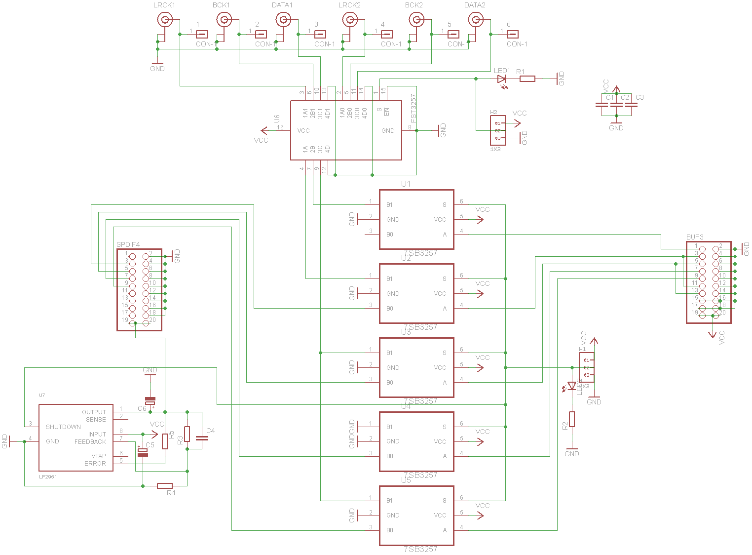
This is the schematic:
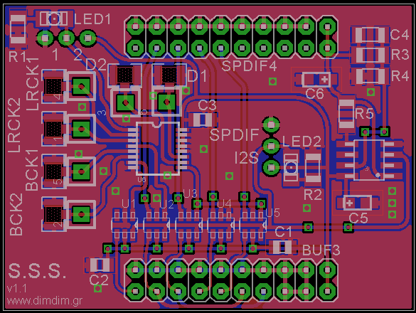
This is the PCB:
Download both files in Eagle format here:
This is the assembled PCB in action:
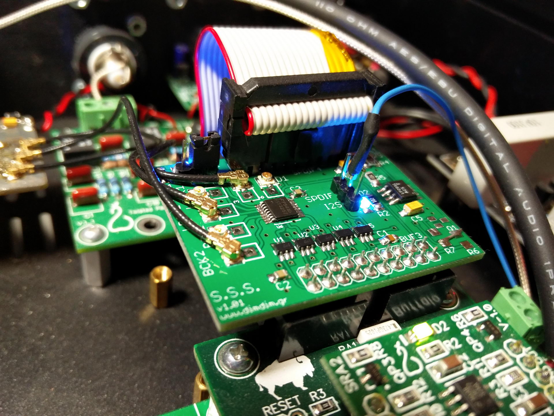
(note that this is actually Rev.1.01, while the schematic & PCBs shown above are Rev.1.1. With Rev.1.1 I fixed a small bug, so small that I didn’t see the need to have new PCBs made (see missing parts on the bottom right of the PCB))
And this is the BOM:
[table “” not found /]The SSS has the exact same footprint as the original Sidecar. It has the same PCB size and the same connector placement. You could just unplug a Sidecar and replace it with a SSS without worrying about the connectors lining up correctly.
I designed the PCB with U.FL sockets for the I2S signals, but at the last-minute I decided to add support for plain wires as well. Note that the I2S signal do not go through any vias, hence the somewhat “strange” placement of the U.FL sockets.
The I2S source selection is done by connecting an SPDT switch to the header on the top left of the PCB. You may also connect an Arduino to the middle pin. In that case, a logic low will select Input 1 (D1, LRCK1, BCK1) and the LED will remain off. A logic high will select Input 2 (D2, LRCK2, BCK2) and the LED will light.
The selection between I2S sources or S/PDIF is done by connecting an SPDT switch to the header situated near the middle of the PCB. You may also connect an Arduino to the middle pin. In that case, a logic low will select S/PDIF input (and also enable the LDO that powers the 4-Channel S/PDIF) and the LED will remain off. A logic high will select I2S sources and the LED will light.
Next on my to-do list is to try to see if there exist measurable differences in sound quality (vs. the Sidecar). I’ll keep this page updated.
As always, I have a small surplus of PCBs (Rev.1.01), so if you’re interested in one (and don’t feel like making your own) you should just let me know.