
A while back I decided to build a proper power amplifier for my setup. I wanted it to be very good sound-wise, but also quite powerful since my speakers like a lot of power.
It would also have to be a 3 channel amp, driving my center channel as well as my main speakers.
After a lot of research, I settled on using Hypex UcD Amplifier Modules, in my case the UcD400HG.
I also decided to use matching switching mode power supplies by Hypex, the SMPS400A400.
Hypex recommends that the LM4562s used as buffers be powered by off-board high quality power supplies, so I decided to go that way.
The construction was to be monoblock-style, with a dedicated LM4562 power supply and SMPS per channel.
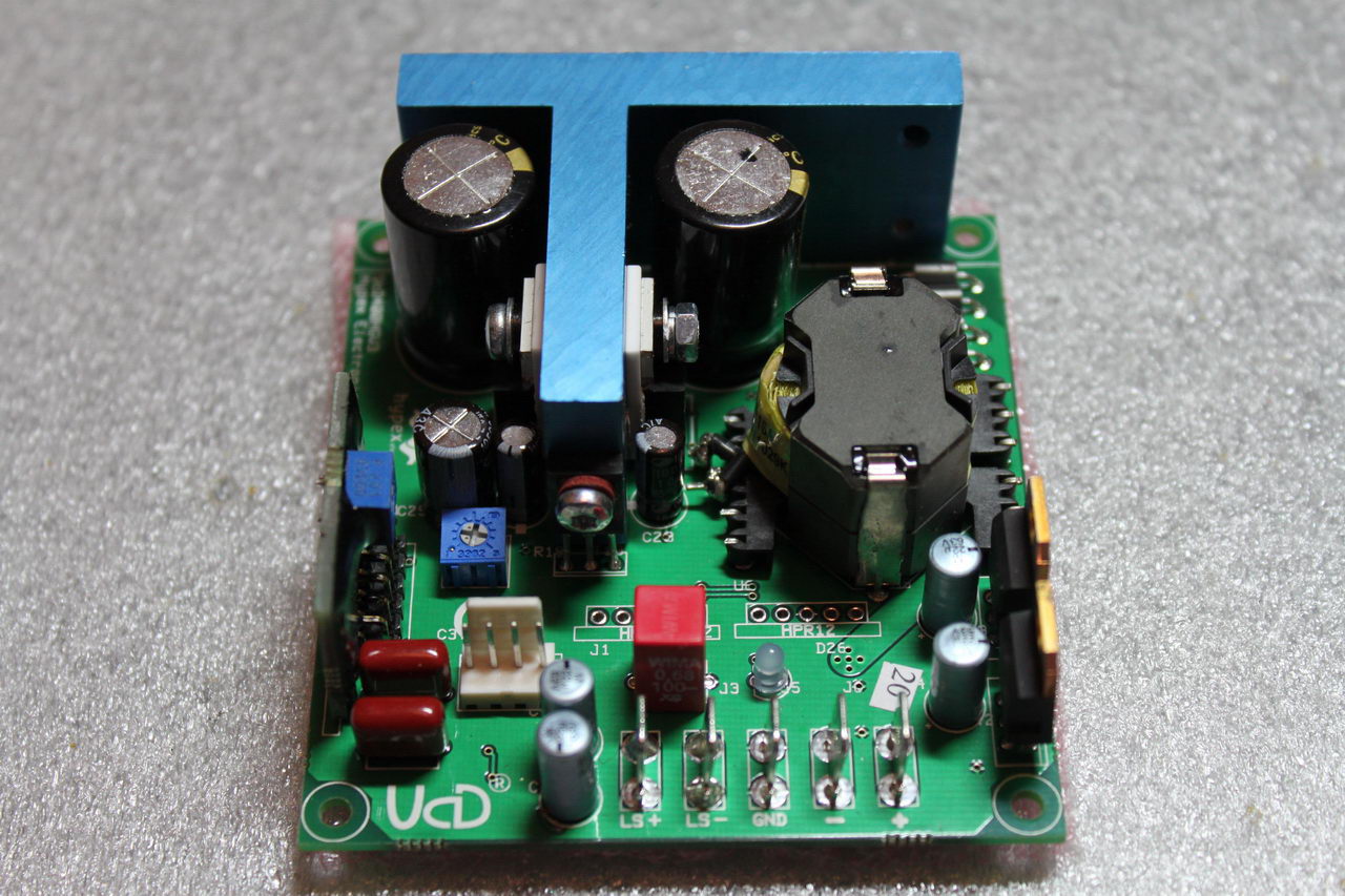
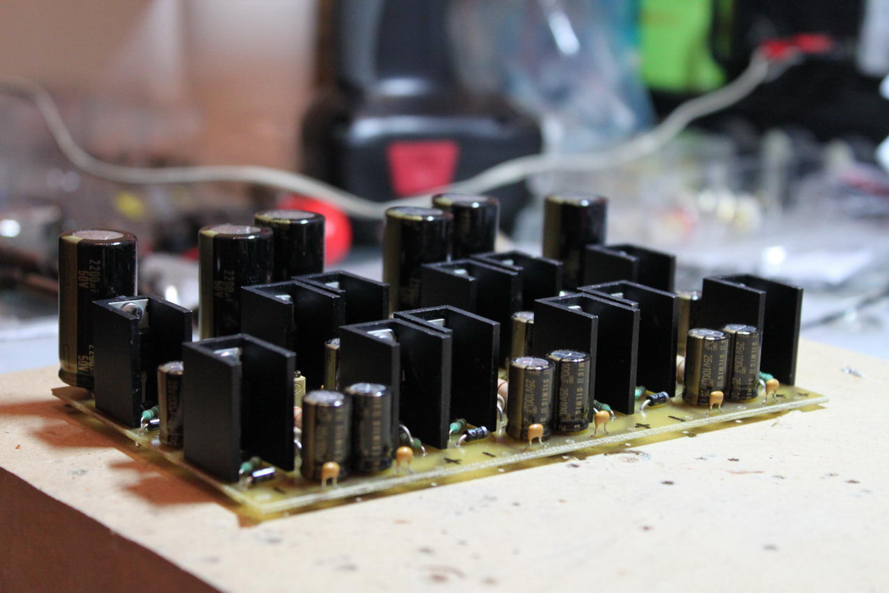
It may appear to be a simple design, using only a handful of parts, but a look underneath the PCB tells a very different story:
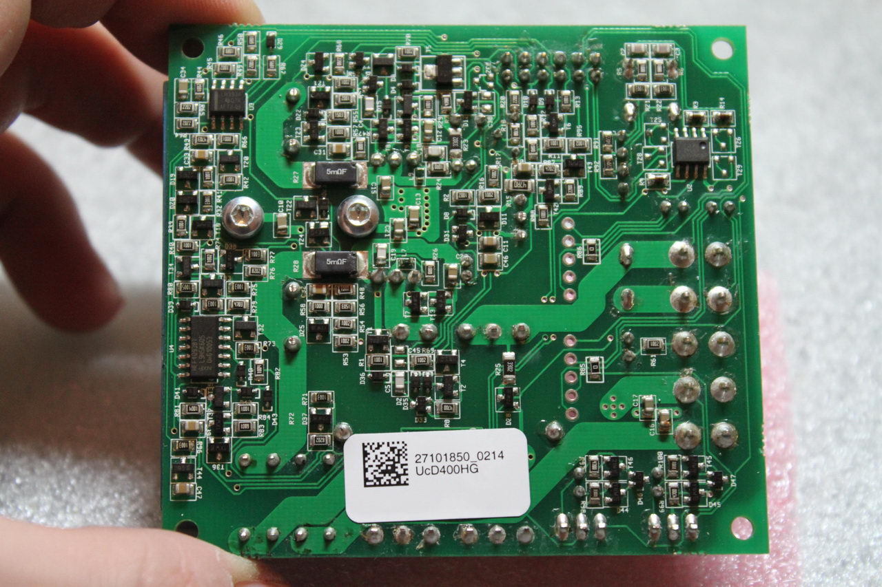
So, it is not what you would call minimal. But it is top-notch, technology-wise.
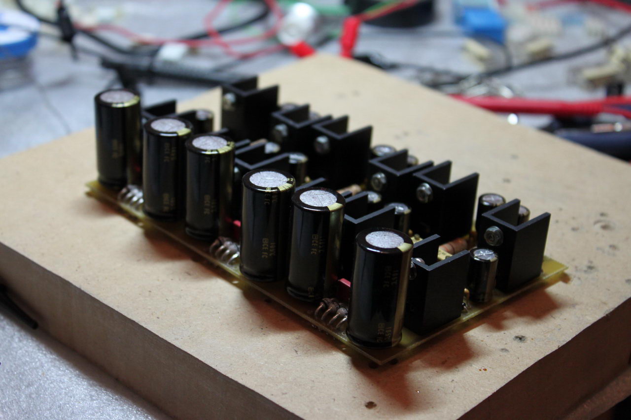
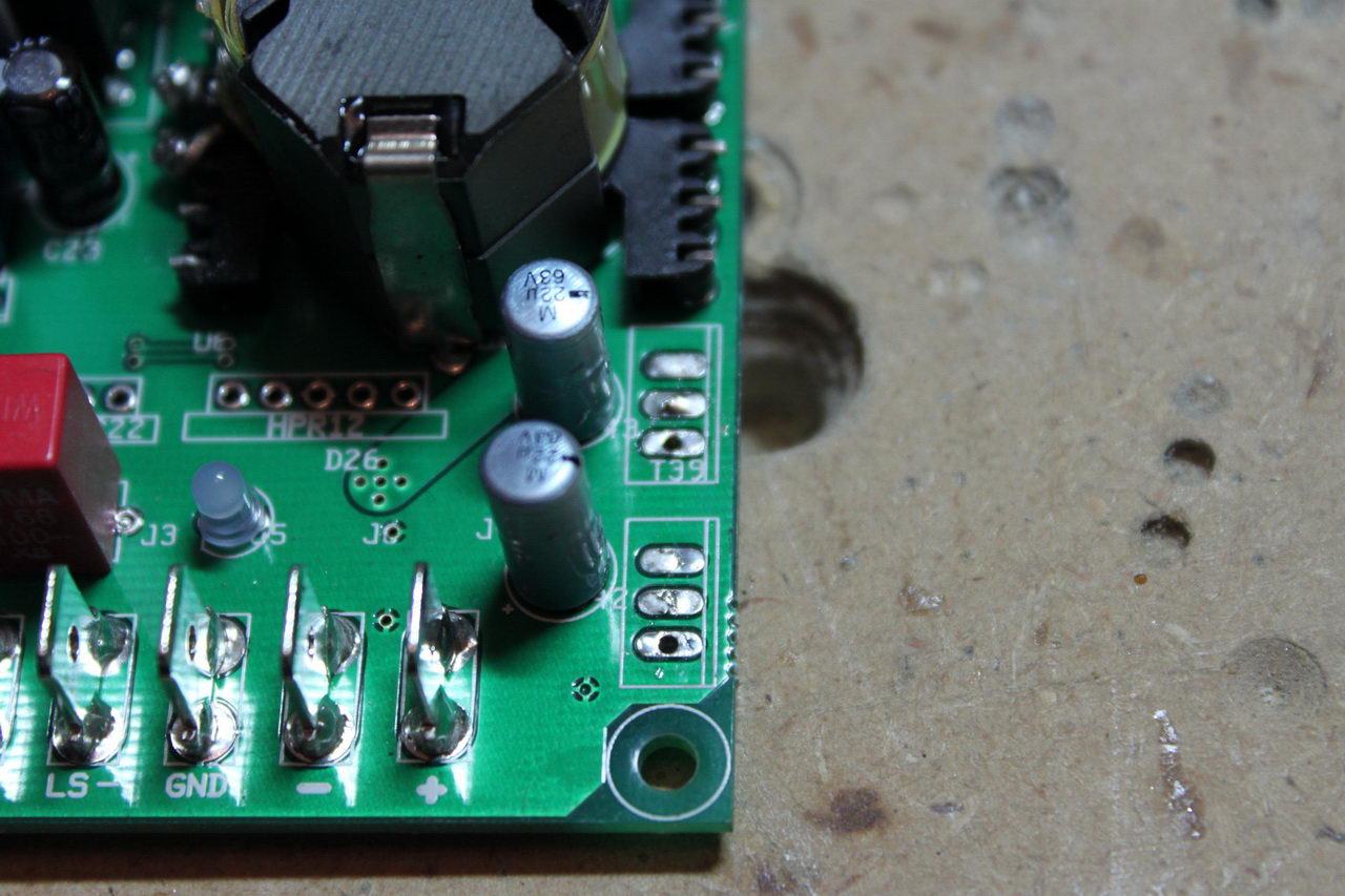
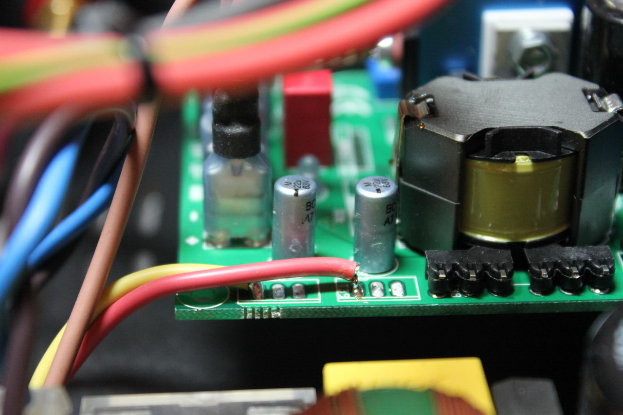
The same applies to the SMPS:
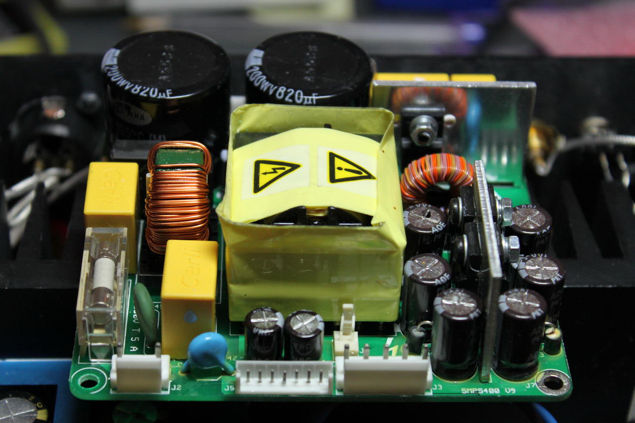
It is designed specifically for the UcD400 and is rated at 400W continuous output (650W short term).
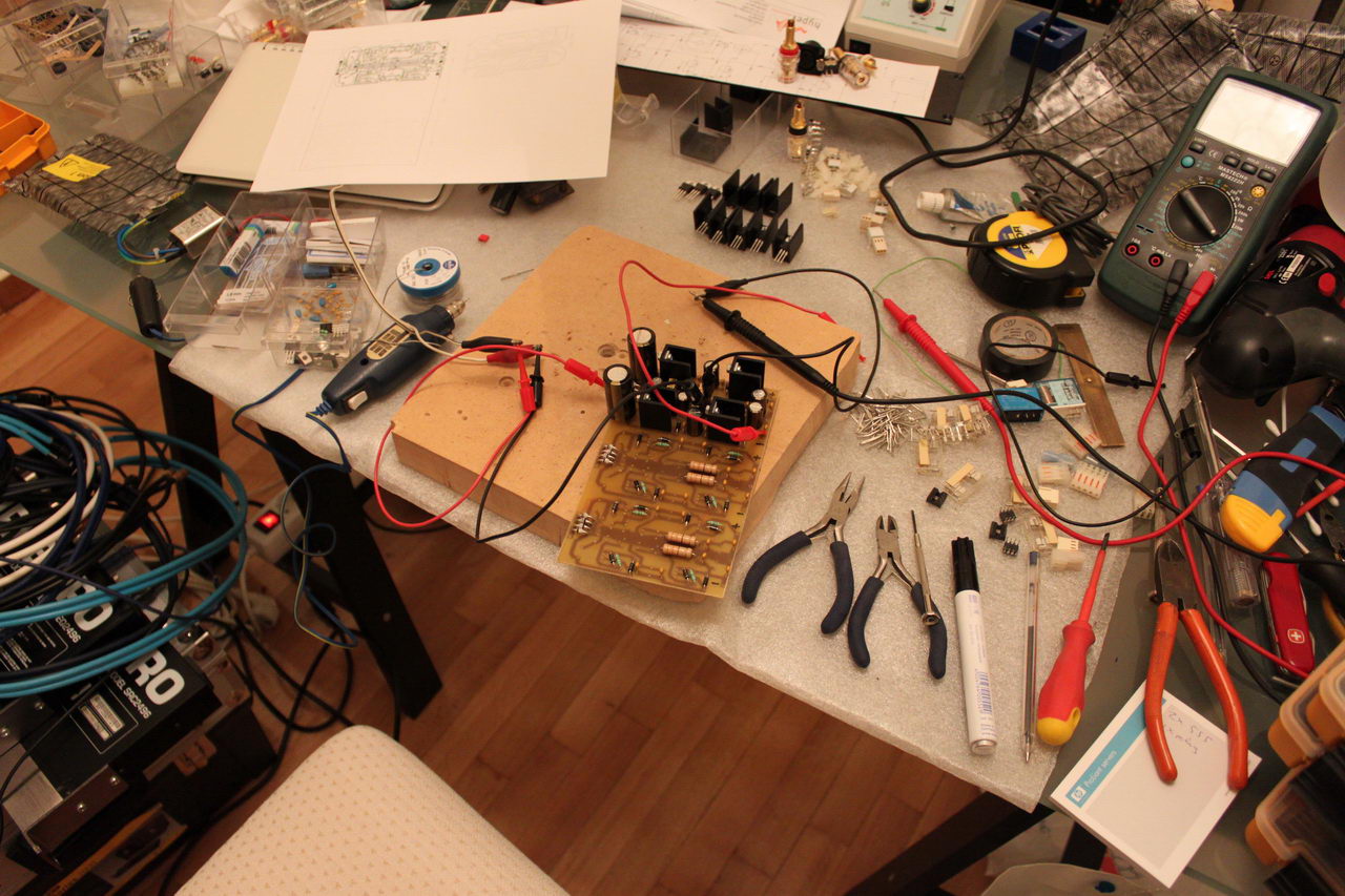
With all that in mind, I purchased a 2U aluminum chassis from modushop.biz and proceeded to test out the layout I had in mind. The idea was to use the chassi’s aluminum sides as heat sinks for the L-R channels and use a hefty but not extreme heat sink for the center channel.
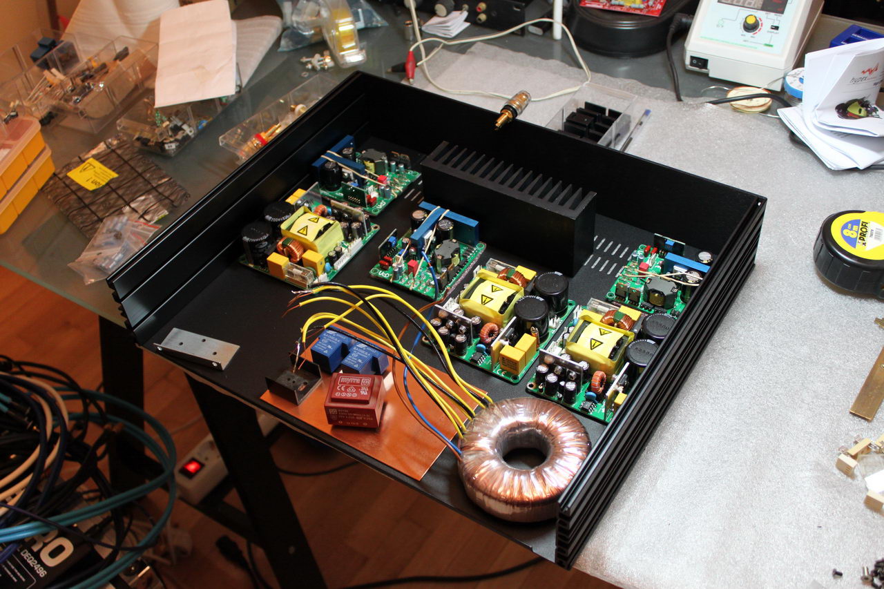
All looked well so I proceeded to construct the LM4562s power supplies.
I chose to go with the tried and true cascaded dual LM317/337 topology. using high quality components and overengineering things as much as possible (ok, practical). I estimated the total consumption of the 3 LM4562s to be well under 100mA, so I went for a 100VA toroidal transformer with three separate center-tapped windings. Yeah, I know.. but I did say that I was going for an overengineered power supply, didn’t I?
For the main filter capacitors I went with Panasonic FCs, and I used Wima MKP, Elna Silmic II and multilayer ceramics throughout the circuit.
I designed the circuit and the PCB in Diptrace. You can download the full schematics and PCB here:
I developed and etched the PCB in-house and began construction:
A short while later I was done:
I proceeded to connect it to the transformer and make the necessary adjustments in order to get the desired output of +/-12VDC.
Next up was the rear of the chassis. With balanced & single ended inputs and 3 channels total I had my work cut out for me.
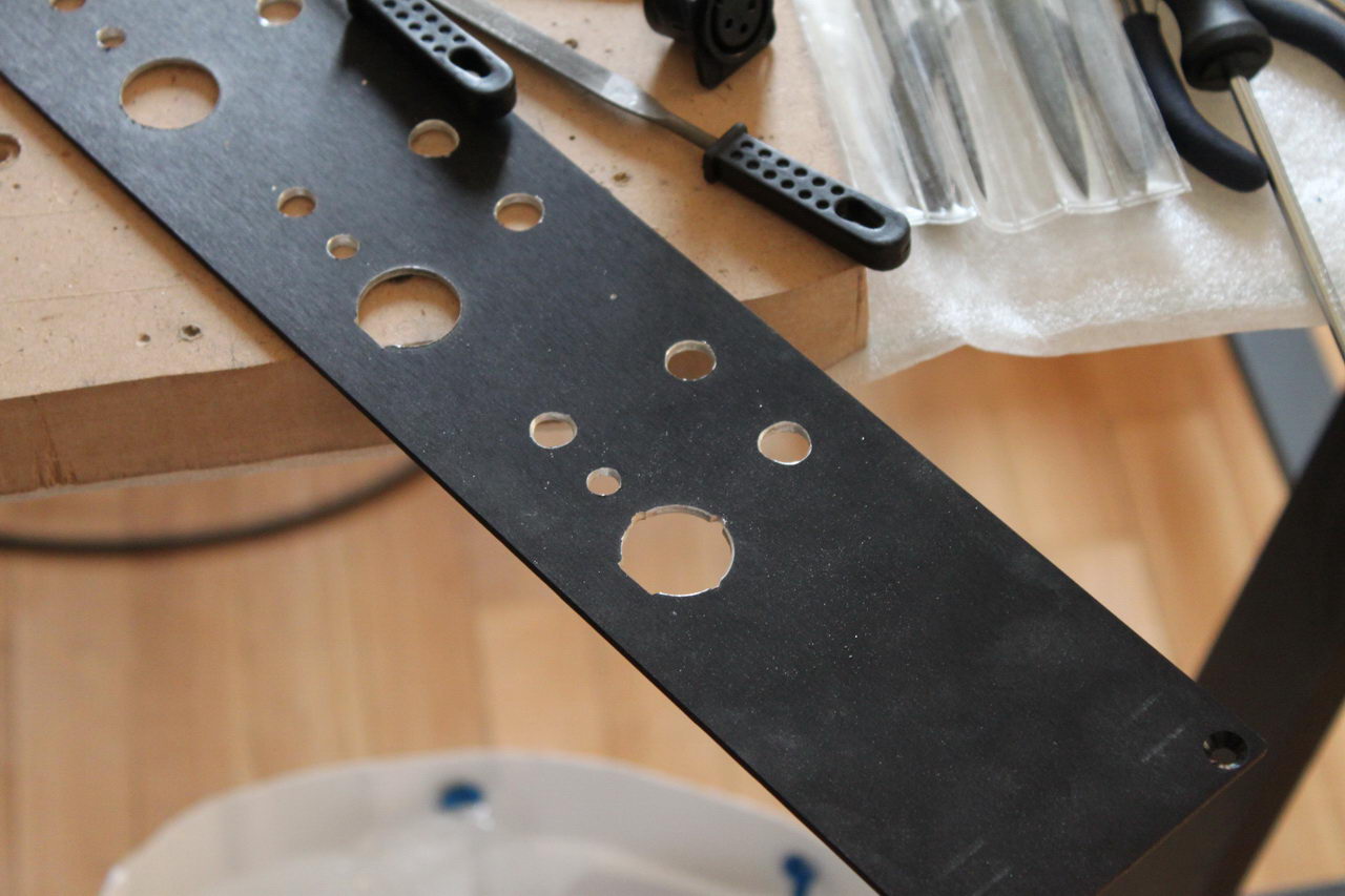
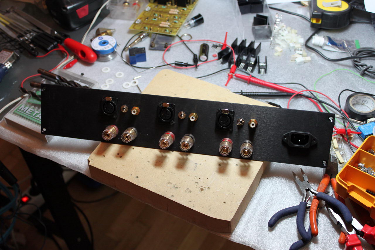
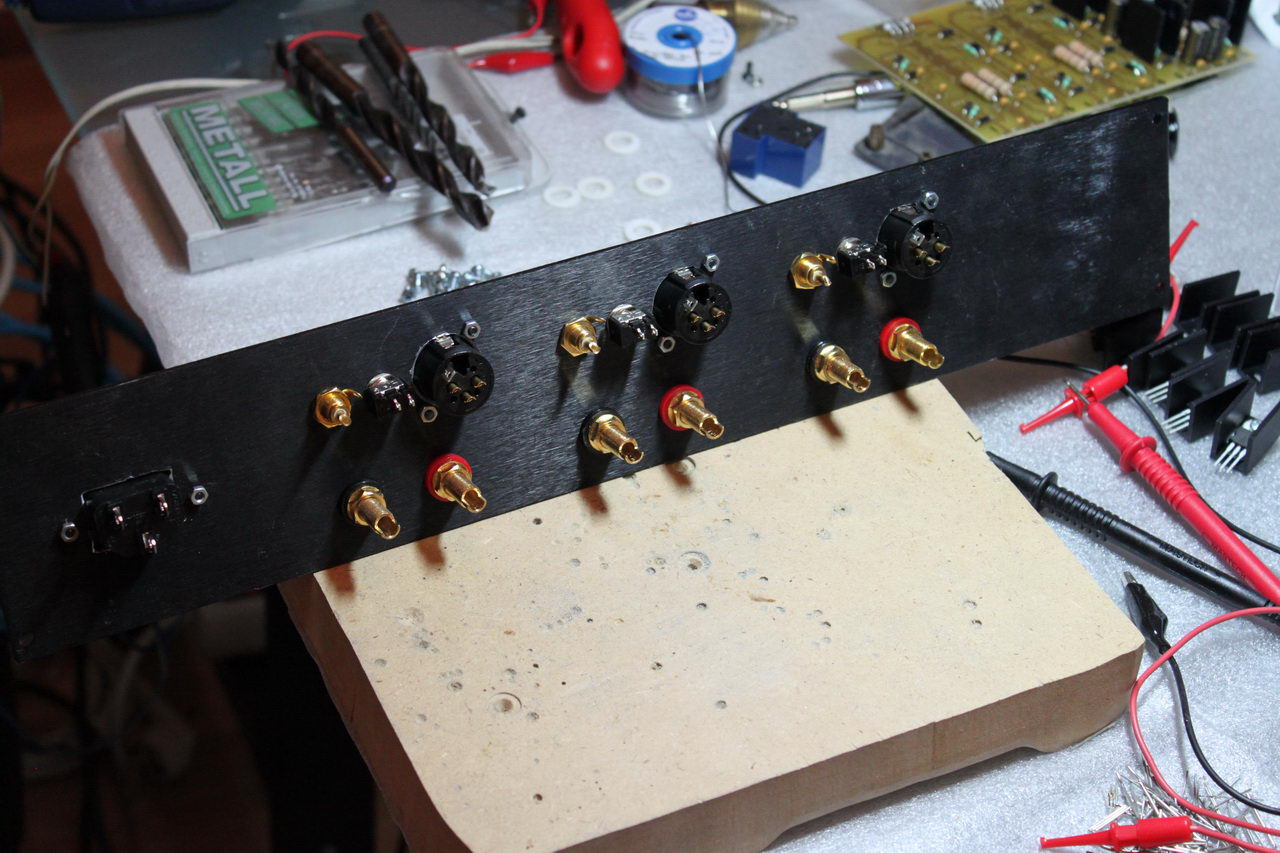
I think it turned out OK. Next up, I had to modify the modules since I wanted to use an outboard aux power supply. That meant desoldering the power transistors that do most of the work:
and soldering in lines to the aux power supply:
Perfect!
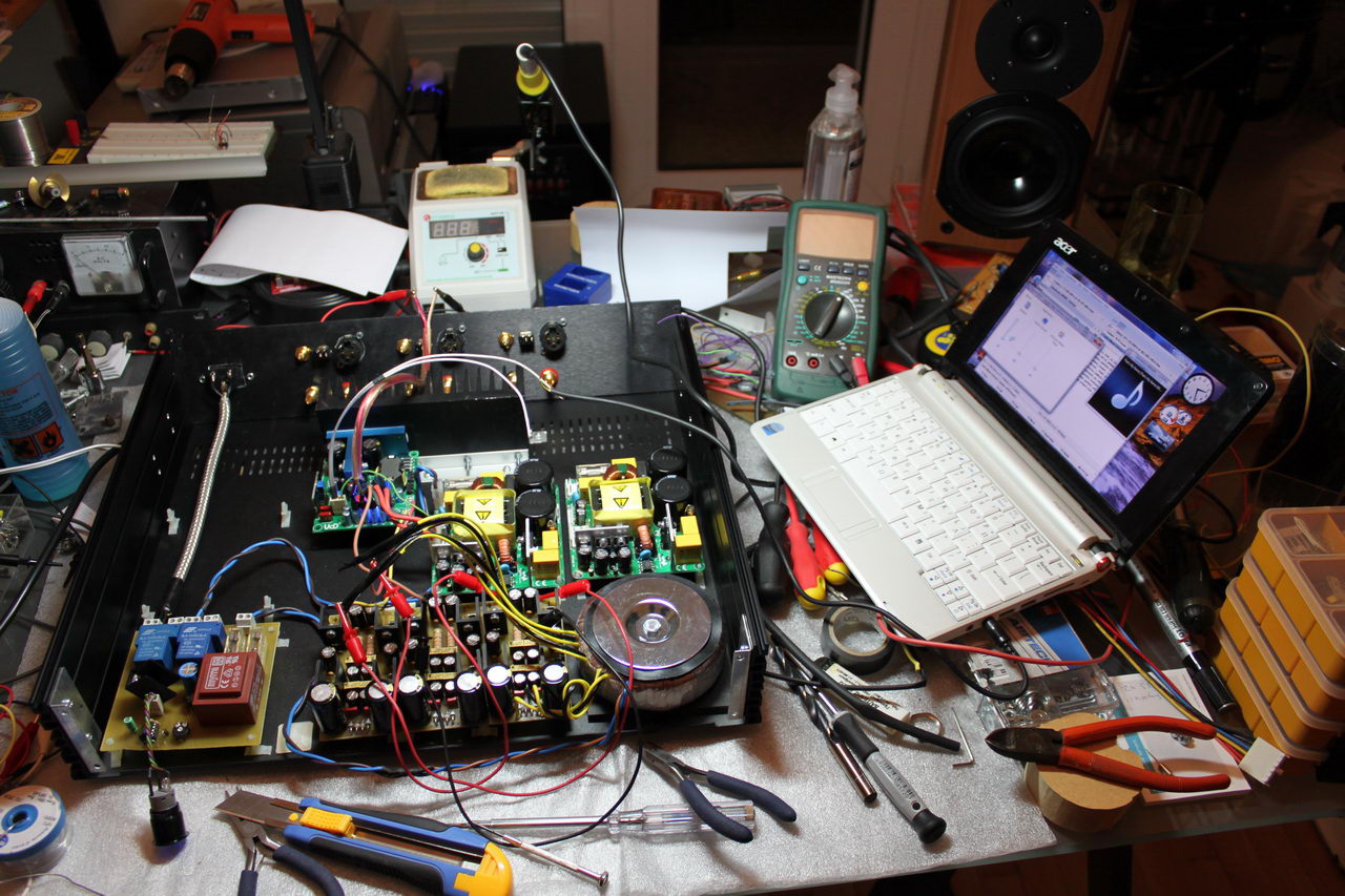
It was time for a test run:
Everything went according to plan, no magic smoke was released, so I proceeded to the final assembly. This was the end result:
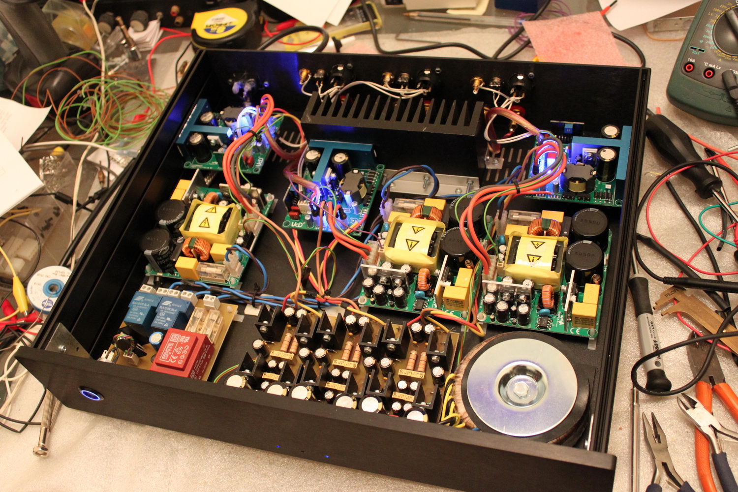
Meanwhile, I had built a little power control board, seen above on the bottom left. Nothing fancy, just a stand-by power supply, the necessary fuses and a couple of high current relays. But once a while, upon power-on the amp would trip the power outlet’s 10A fuse. I had read that the SMPS’ had built-in soft-start circuits, so I didn’t think that it would be a problem, but it was. That led me to think up of a new power control board:
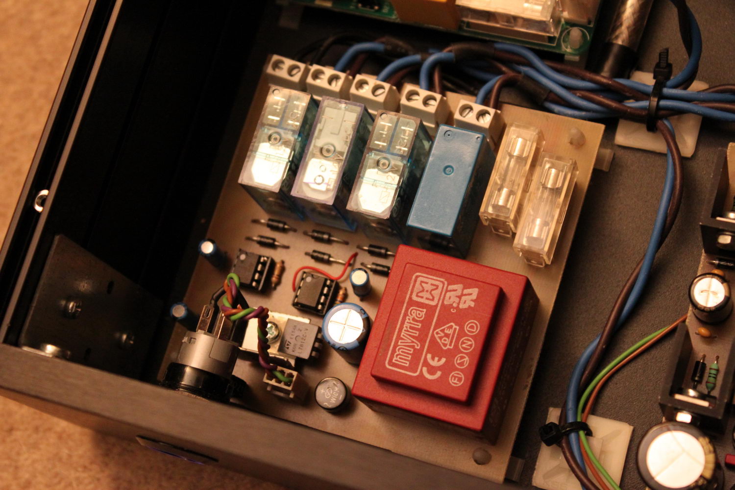
Again, it was nothing particularly sophisticated, just 4 relays, each powering a discreet power element (3 for the SMPS’ and 1 for the aux power supply). The timing of the relays was controlled by three 555 timer ICs, set to monostable mode and each adjusted to a different time period. Thus I had a “staggered power-on” circuit.
This is what the amp’s startup looks like:
Input selection update:
Originally I had used a small switch to select either balanced or SE input to each of the channels. That worked OK, but eventually I wanted to have remote control of the input selection, as well as a better overall solution. That led me to design a small PCB that would house a small signal relay and some control elements. I built three such PCBs and installed them in the amp:
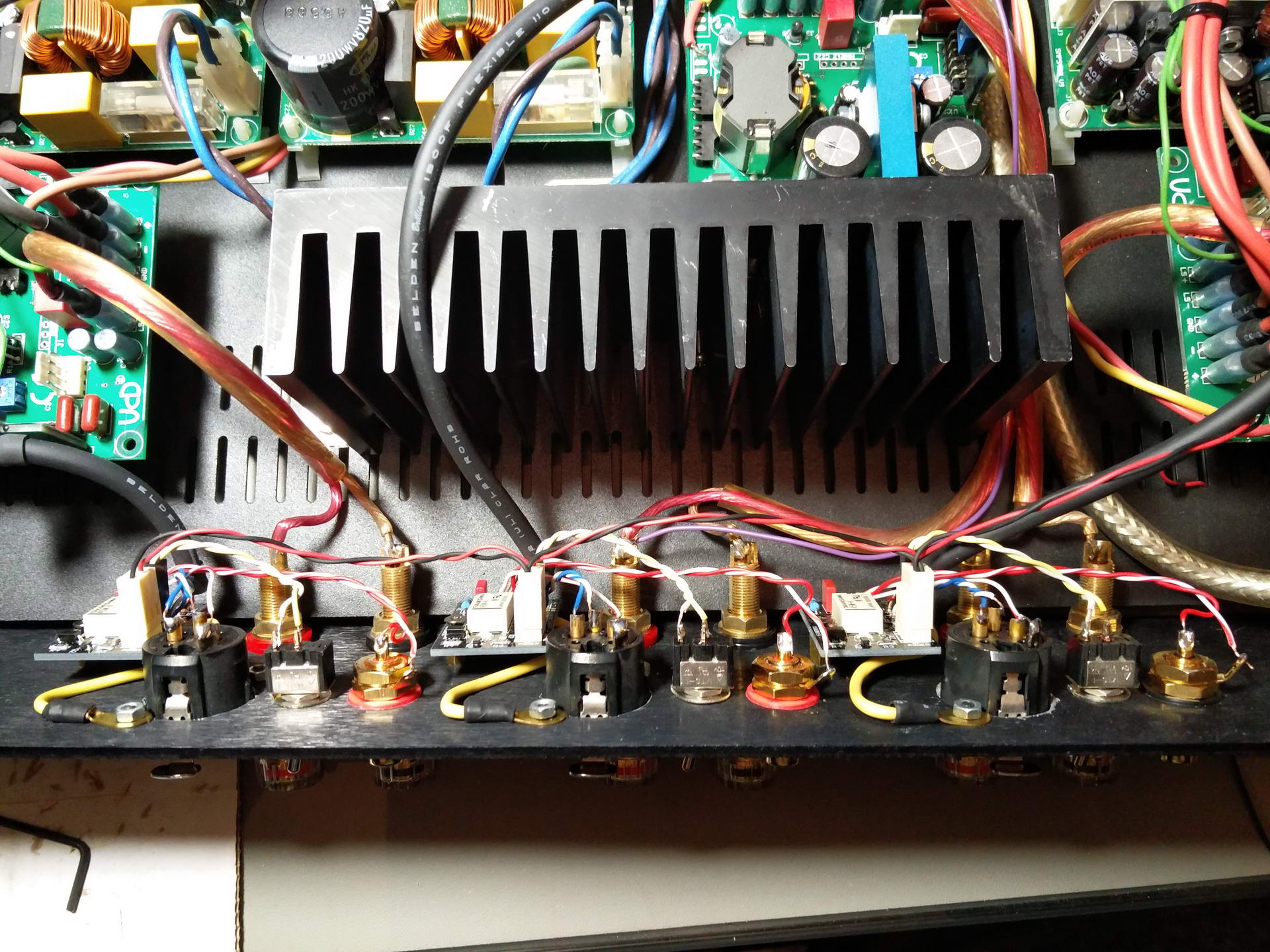
I decided to include manual selection of input via toggle switches as well.
I designed the PCBs according to Hypex’s relevant Application Note, see paragraph 4.5.
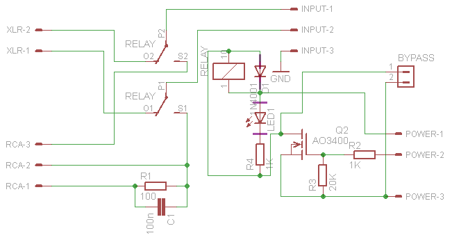
This is the PCB’s schematic:
And here are both the schematic & PCB in Eagle format:
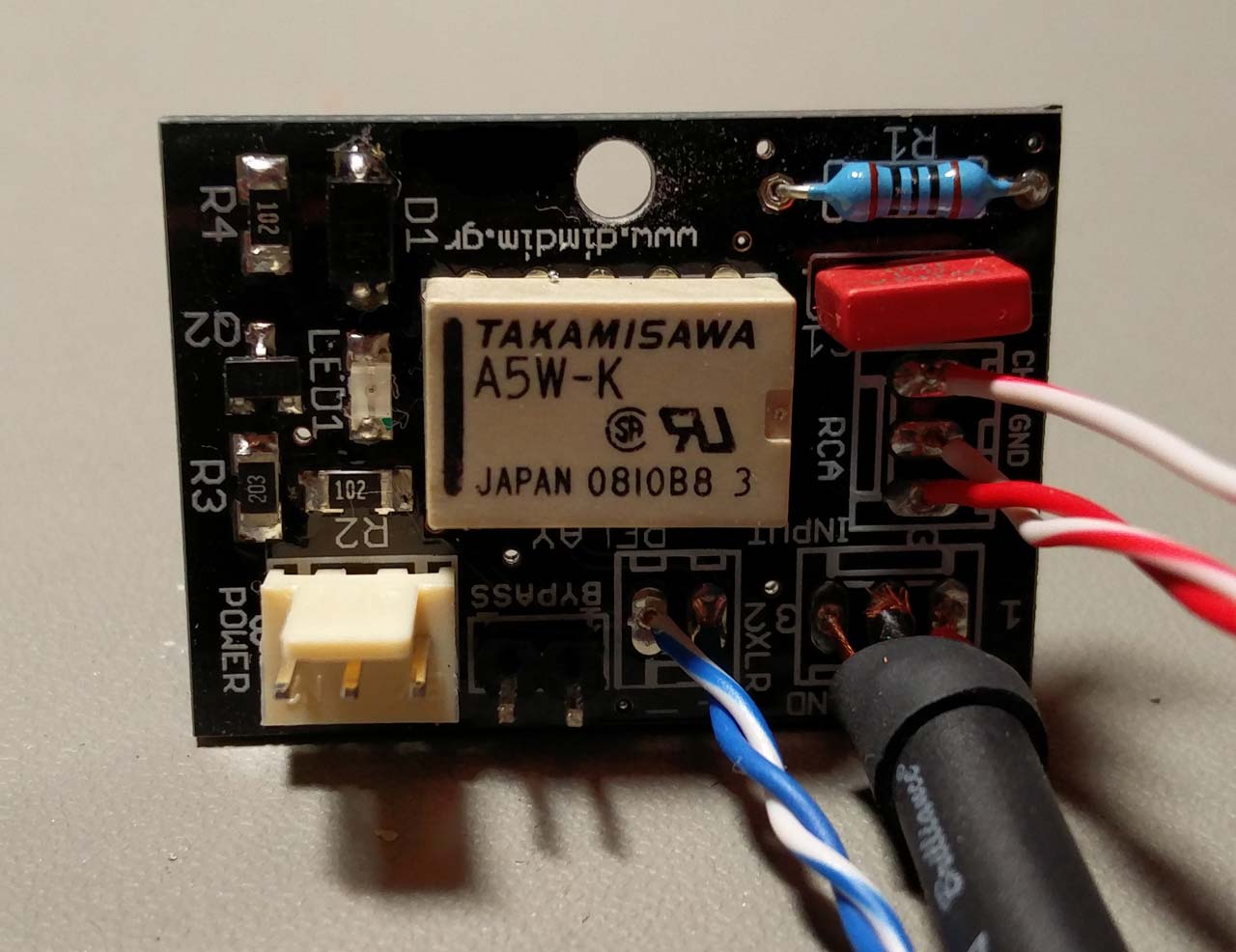
This is a fully assembled PCB:
The Power header of for connecting +5V, control, and GND. A logic low at the control pin selects the balanced input, a logic high the single ended.
The Bypass header is for connecting a switch to be used as manual selection between inputs.
The XLR header is for connecting the + & – pins of the XLR socket. Pin 1 of the XLR socket should be connected to the chassis.
The Input header is for connecting to the UcD400’s inputs.
The RCA header is for connecting to the RCAs mounted to the chassis. They should be electrically isolated from the chassis. There are three pins. + should be connected to the RCA’s central contact, GND to the RCA’s shield and CHA to the chassis, near the RCA (I for example connect it to the XLR’s chassis terminal, see pic above).
Each PCB’s ground should be connected to the chassi’s ground, close to the PCB. I used short pieces of wire (yellow color, see pic above) soldered to the underside of the PCB on to the GND connection of the Input header and bolted to one of the XLR’s screws.
The power line’s ground should also be connected to the chassis.
This exact method of grounding virtually guarantees no problems due to ground loops (no humming etc). My amps are dead quiet.
build looks pretty cool. I am looking into Hypex now and think a 3 channel system would be a good deal. Didn’t know on which modules I want to go with yet though. How do yours sound? what speakers are you powering?
The Hypex amps are pretty great if you need a lot of power without sacrificing SQ. I am enjoying mine with a pair of semi-DIY Arcos II speakers. My center channel is also DIY, using Seas units.
‘The XLR header is for connecting the + & – pins of the XLR socket. Pin 3 of the XLR socket should be connected to the chassis.’
Usually pin 1 of the XLR is tied to gnd.
Cool project, by the way.
I can’t believe an error so obvious made it so long without anyone noticing.. 🙂 Fixed.. And thank you for your kind words. 🙂