
Why bother?
If you are reading these lines, you are probably into DIY audio. A big part of DIY audio is building DACs. Since these last few years DACs have become fairly complex, sometimes they can benefit from being controlled by microcontrollers. I myself own two such DACs, a Buffalo III and a Soekris dam1021. I have written code to control them with the help of Arduinos, but early on I realized that I also needed to have electrical isolation between the Arduino and the DAC, in order to eliminate the possibility of interference and/or noise. To accomplish that I had designed a little Arduino shield.
The years passed and my needs changed with the introduction of the dam1021 DAC and its serial interface. Even though this interface is electrically isolated from the dam board, it is not isolated from the USB to I2S interface. This means that my Arduino would have to share a common ground with my XMOS-based USB interface. I did not want that to happen.
My first thought was to design a new shield specific to the dam but then I thought “why not design a universal isolator shield?”. It would provide electrical isolation for both I2C as well as serial signalling.
Thus was born the Universal Signal Isolator shield for the Arduino DUE: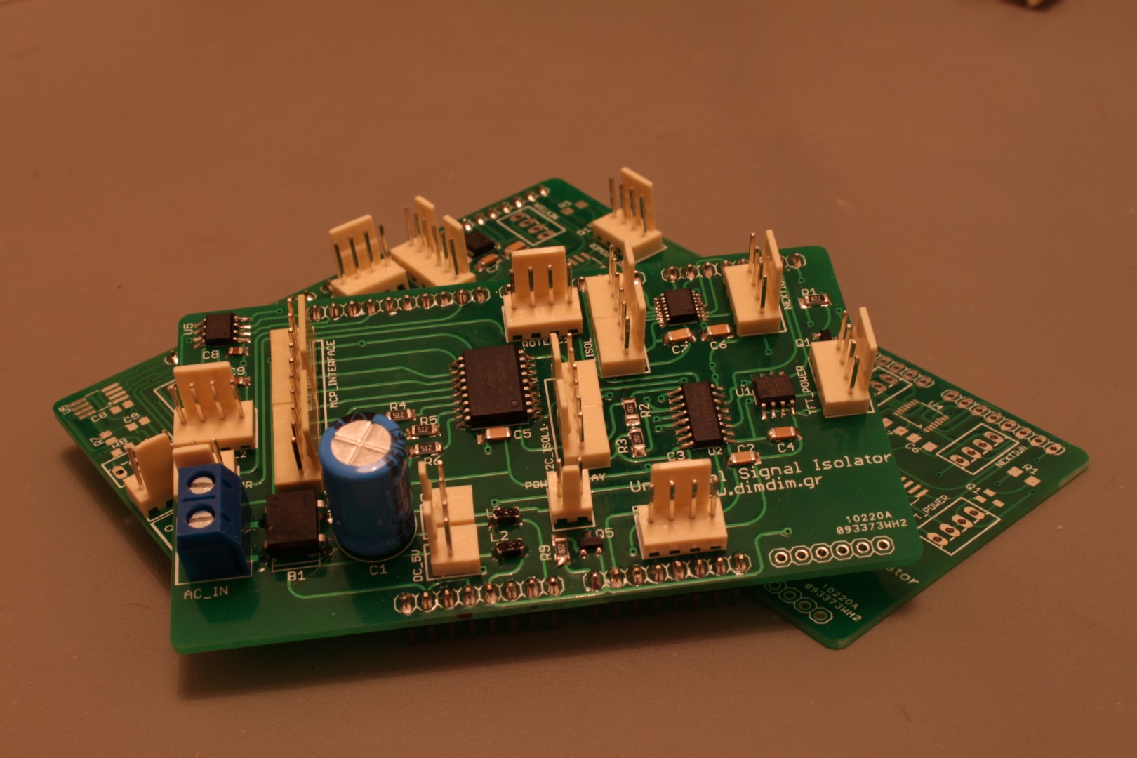
The original design was completed around September 2015, but since then there has been a lot of interest in this design so I have been further optimizing it.
The result of this optimization was a short run of Rev. 1.1 boards (very similar to the original design) and then finally this PCB:
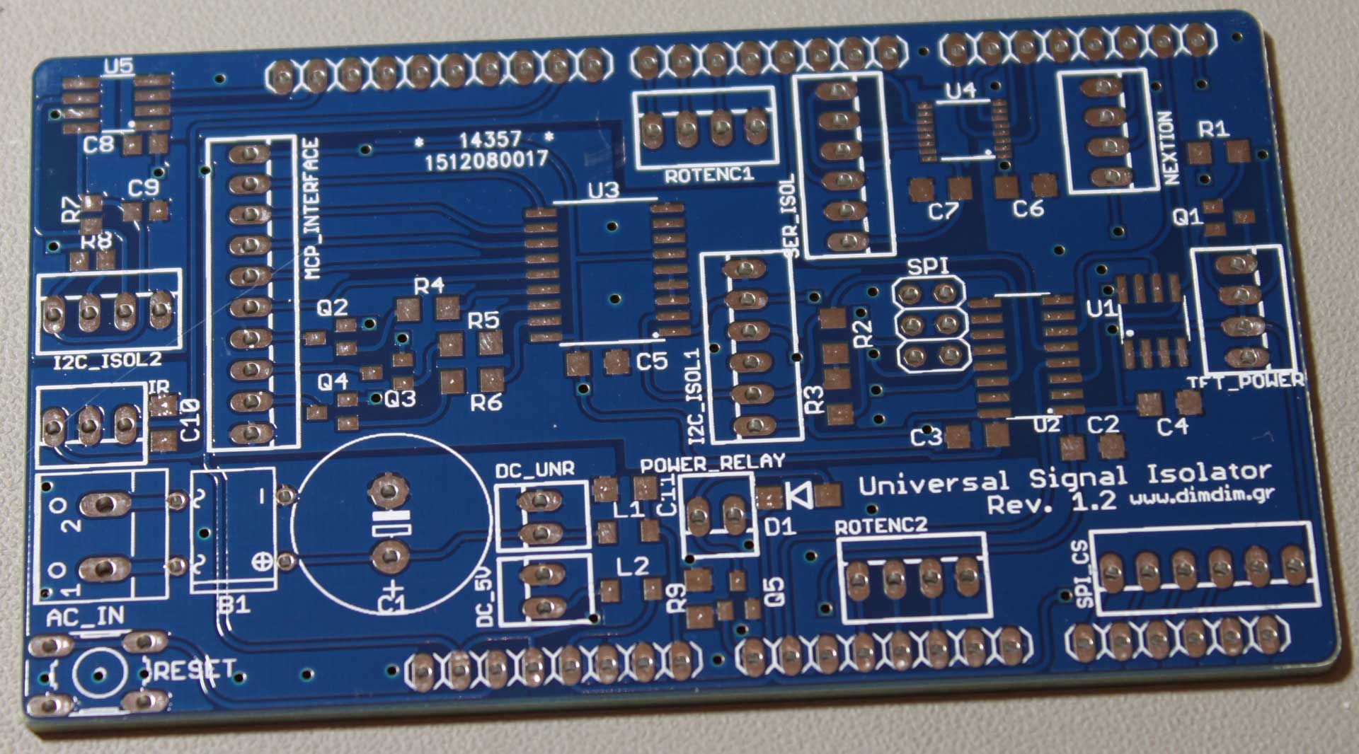
It’s called “the Rev. 1.2”. I have introduced it in this post, detailing the changes from the original design. The following documentation pertains to the newer design. The documentation for the original design (in archive form) can be found here: Universal Signal Isolator shield for the Arduino DUE (Rev.1).pdf (3286 downloads )
Specs
So, what does this thing do?
- Electrical isolation of I2C signals, complete with support of 8 isolated inputs or outputs (via an MCP23008 IC). Three of the MCP’s pins are high current outputs (up to 100mA).
- Electrical isolation of up to 2 serial ports (implemented with an Si8642).
- Electrical isolation of the second I2C interface of the DUE (implemented with an ADUM1250).
- Powered either by 5VDC, 8-15VDC (non-regulated) or 7-12VAC (includes support for on-board rectification and filtering).
- Support of a 5VDC power-on relay (up to 100mA).
- Header for connecting a Nextion display (for future use – not yet supported by any of my code!).
- On-board EEPROM memory (24LC256).
- Passthrough for the DUE’s SPI header and relevant CS pins.
- And of course full compatibility with the previous shield (same pinouts for the encoders, IR, TFT, etc.).
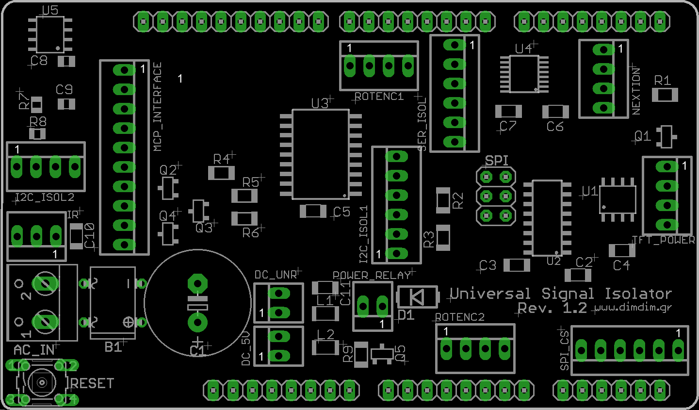
Schematic & PCB
This is the schematic & PCB of the board in Eagle format (v1.37, a.k.a. “Rev.1.2”): USI Schematic & PCB (4429 downloads )
How do I make it work?
Power
You have five ways of powering your Arduino & Shield:
- Through one of the Arduino’s USB ports. I use this way only for testing – it’s not very practical once you have your Arduino inside a chassis. Still, it will work just fine and you do not need to install any of the power-related parts of the shield.
- Through the DUE’s DC in jack.
- Through the DC_5V header. Here you need to supply 5VDC. No more, no less. Your power supply needs to be regulated and be capable of supplying between 250-350mA of power, depending on whether you will be driving a power relay or not. You need to solder on L2 and the relevant header.
[table “” not found /]
- Through the DC_UNR header. Here you need to supply between 8 and 15 VDC, but it may be non-regulated. The Arduino’s reg will do the regulation.You need to solder on L1 and the relevant header.
[table “” not found /]
- Through the AC_IN header. Here you may connect a transformer with a secondary winding of 7-12VAC, rated at at least 5VA. If you choose to go this way, you need to install B1, C1, C11 and L1 besides the relevant header. The shield takes care of the rectification and the filtering but the Arduino does the regulation.
Basic connectivity
You really should install U1 and C4. Both TFT HiFiDuino and ArDAM1021 now make use of this memory to store DAC settings.
If you will be using the shield with a 3.2″ TFT, you will need to install R1, Q1 and TFT_POWER. This is the pinout of TFT_POWER:
[table “” not found /]The current versions of TFT HiFiDuino and ArDAM1021 still make use of only one of the two supported rotary encoders, so you can get away with installing only ROTENC1.
[table “” not found /]
If you will be using an IR control (what are the chances of you not using one, right?), you will need to install C10 and the IR header.
[table “” not found /]
If you will be controlling a power on/off relay, you will need to install R9, Q5, D1 and the POWER_RELAY header.
[table “” not found /]
Isolated I2C ports
You may enable either the first I2C port (I2C) or the second one (I2C1) or both.
- To enable the basic functionality of the first port, you need to install U2, C2 and C3. The resistors R2 & R3 are pullup resistors and you may need to install them depending on your DAC’s I2C lines. If they already have pullup resistors (like in the case of the TPA Buffalo III) you do not need them. Power to the isolated side is provided by I2C_ISOL1, pins 1 (+) and 6 (-).
[table “” not found /]
- To enable the 8 isolated inputs/outputs, you need to also install U3, C5, R4, R5, R6, Q2, Q3, Q4 and of course the MCP_INTERFACE header. In this case, power to the isolated side my be provided either through the I2C_ISOL1 header or through the MCP_INTERFACE header (pin 1 (+), pin 10 (-)).
[table “” not found /]
- To enable the second port, you need to install U5, C8 and C9. The resistors R7 & R8 are optional pullup resistors (see first case above). Power to the isolated side is provided by I2C_ISOL2, pins 1 (+) and 4 (-).
[table “” not found /]
Isolated Serial Ports
The shield supports two (2) isolated serial ports, SERIAL2 and SERIAL3. They share one power supply and have a common ground, since they are both supplied from the same one isolator IC, U4. You will also need to install C6, C7 and the SER_ISOL header. Power to the isolated side is provided by pins 6 (+) and 5 (-).
[table “” not found /]
SPI PORT
The shield supports passthrough of the DUE’s SPI port, in case your design has a use for it. It is provided by soldering on an SPI header and the SPI_CS header.
[table “” not found /]
Do you have one for me?
I try to keep a few boards around, since friends ask for them all the time. Contact me.