
Granted, s/pdif is on its way out now that we have mature, high-speed asynchronous USB interfaces, but still it will be a long time before it is considered completely obsolete.
With that in mind, for a long time I’d wanted to design a proper s/pdif receiver using the well-known and respected WM8805 IC.
For me, it ticked all the necessary boxes:
- Very low jitter (~50ps RMS).
- Support for all popular sampling rates, up to 192KHz / 24bit.
- I2S (or LJ, RJ, DSP) and s/pdif outputs.
- 8 inputs with built-in MUX
- Full software control through I2C or SPI.
I’d actually bought a couple of ICs but kept them in storage for a couple of years, putting off designing a unit until a fellow DIYer and friend had the same idea, pitched it to me at avclub.gr and got the ball rolling.
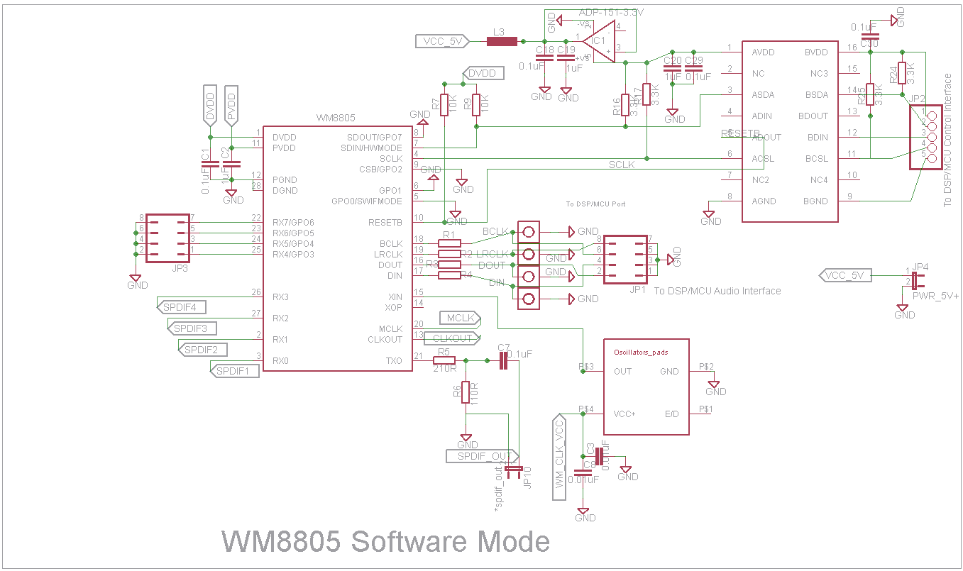
So, let’s start with the basics. The WM8805 is a pretty versatile IC. It can be configured to work in hardware or software mode. Software mode offers a lot more functionality, so software mode it would be.
It can act either as an s/pdif receiver with I2S output or an I2S receiver with s/pdif output. It can also act as a “s/pdif cleaner”, receiving s/pdif, “ironing it out” and re-transmitting it.
We just needed a simple s/pdif receiver with I2S outputs, so we would set it up as such.
But first, I wanted to try the chip out on the breadboard. I set it up according to the reference schematic shown in the data sheet in hardware mode.
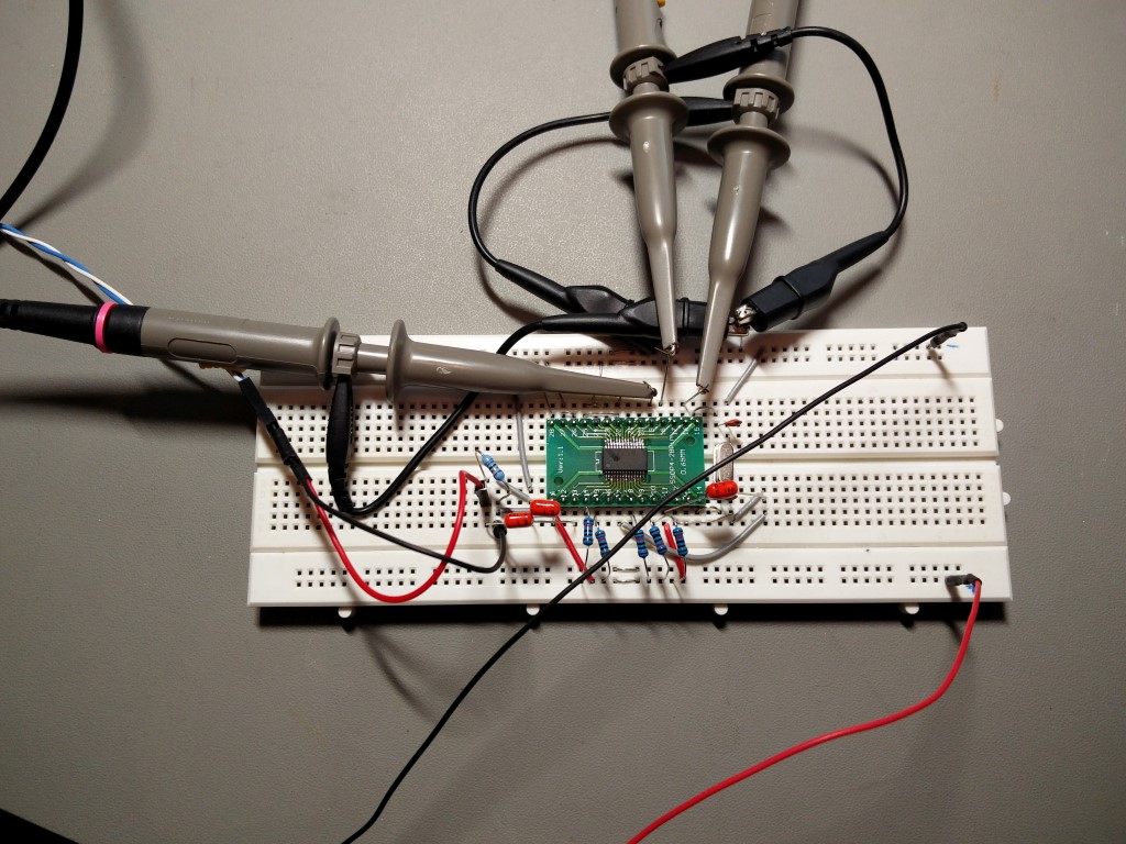
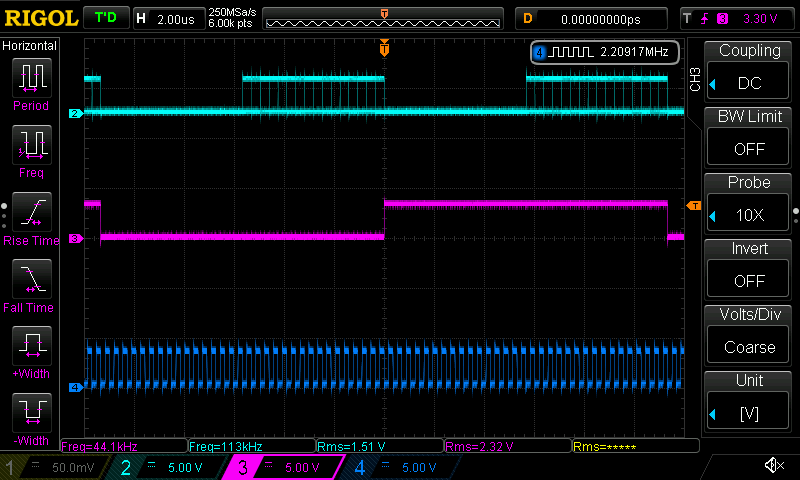
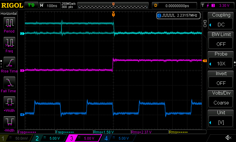
I connected an old DVD player that I keep around as a test s/pdif source with some COAX and powered up. The wm8805 locked in to the signal immediately and gave some pretty good-looking I2S signals (for a breadboard build with no termination):
So we were go for a PCB design. But first, we needed to finalize the design.
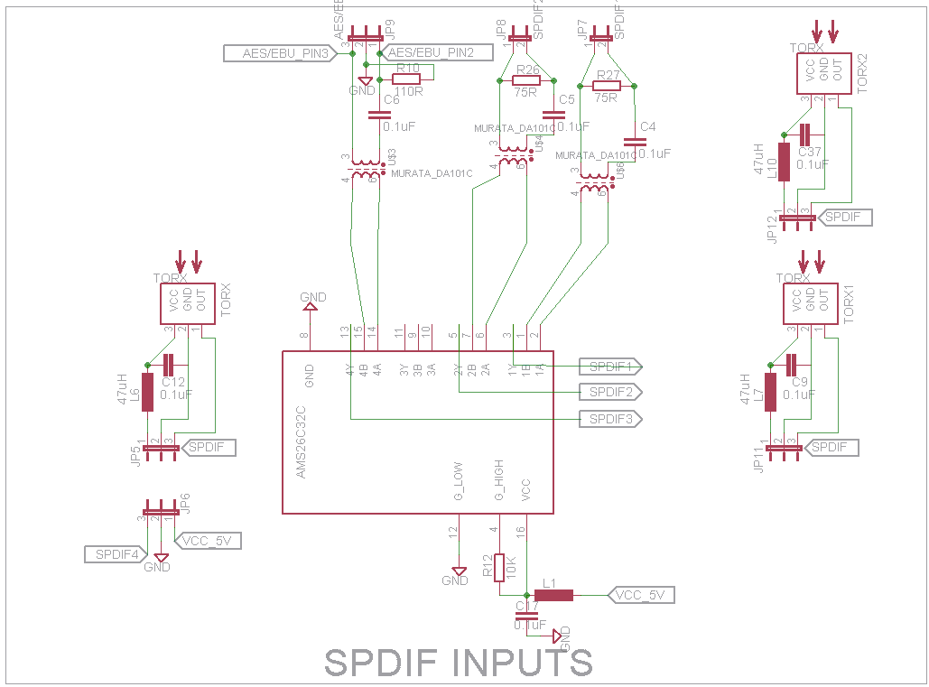
The WM8805’s inputs can be configured to accept either consumer level coaxial s/pdif signals (0.5Vp-p) or TTL-level s/pdif signals. Since there are numerous reports on the web of “coax inputs” not working well (or sometimes, at all), we thought we would include an on-board comparator IC. We chose the AM26C32. This way we would have differential inputs that would be converted to single end TTL level signals. We chose to go by the book, using isolation transformers, DC block capacitors and termination resistors.
A total of 3 coax inputs were implemented, plus an input for a toslink module (5V powered). The remaining 4 s/pdif inputs were brought out to a 2×4 header for future use.
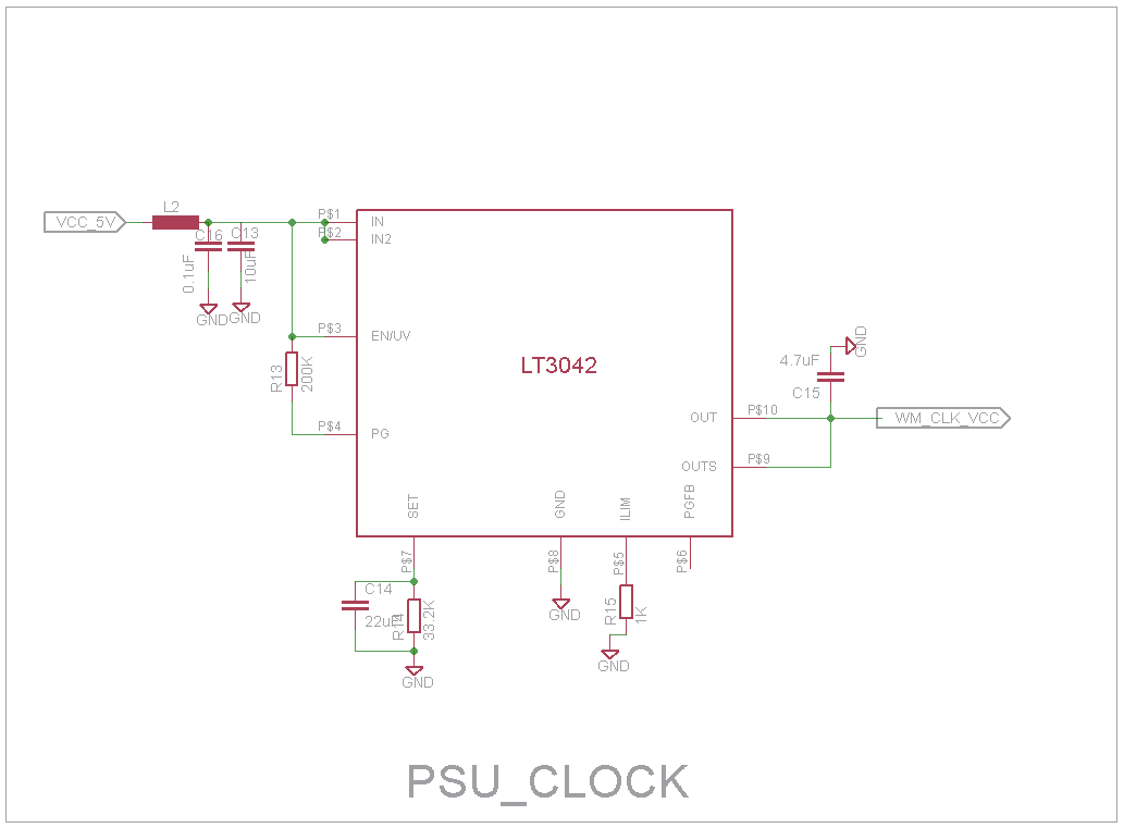
Clocking was to be provided by a 12MHz NDK NZ2520SD low phase noise oscillator, but the part’s footprint was designed to be capable of also accepting Crystek oscillators.
An Si8605AC isolator was used to facilitate galvanically isolated connection to a microcontroller of choice, in our case an Arduino. Besides the I2C lines, the reset line was also passed through the isolator. An added benefit of the isolator was that this way the receiver could be controlled by either 3.3V or 5V logic, like for example by an Arduino UNO.
Signal output was through both U.FL sockets and pin headers. Since the board was designed to be used primarily with ESS DACs, the MCLK output was not routed (I came to regret that decision later..) but the D.IN was. When I eventually ended up needing MCLK output, I decided to make better use of the D.IN U.FL by re-routing it to the MCLK signal output of the WM8805 chip. It was an easy, albeit somewhat ugly, fix.
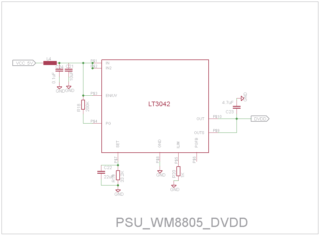
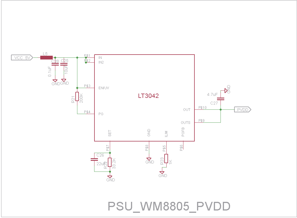
The board was powered by three LT3042 LDOs (2 for the WM8805’s DVDD and PVDD lines and one for the oscillator) plus an ADP151 LDO for the Si8605 isolator. Input to the board would be at 5VDC.
This is the schematic of the core:
This is the comparator:
And these are the power supplies:
This is the complete BoM:
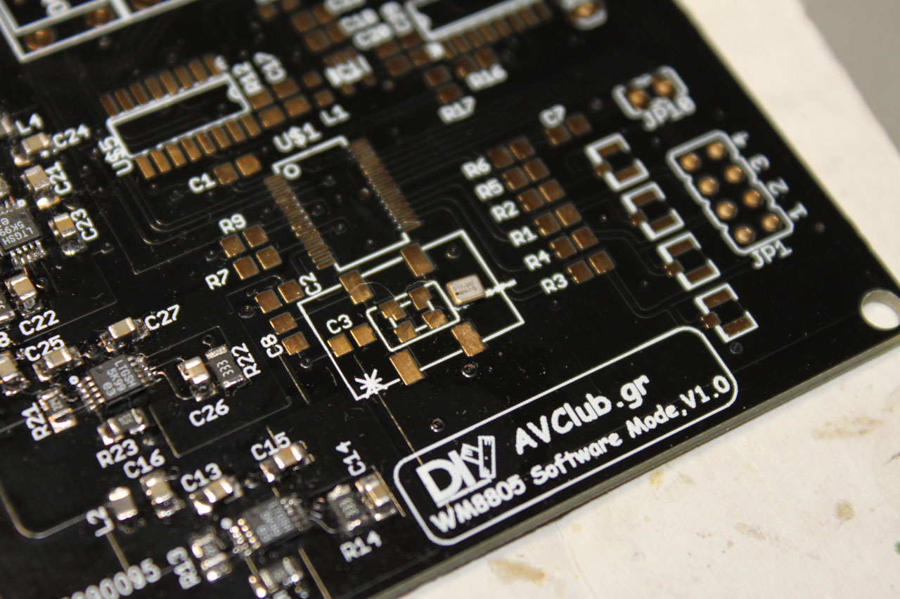
[table “” not found /]My friend Manolis designed a suitable PCB and a set was ordered from www.dirtypcbs.com. After about a month they were delivered.
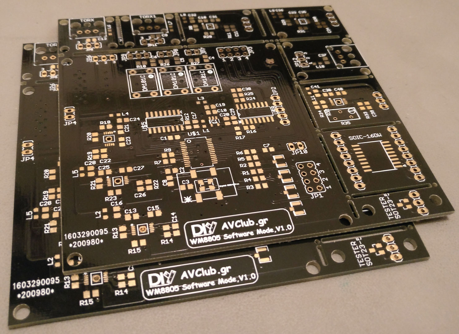
Since there was some space left on the PCB, we decided to take advantage of DirtyPCB’s free panelizing option to include a few extra LDO reg adapters, toslink input boards, etc.
In case anyone is interested, I still have a couple of spare unpopulated boards.
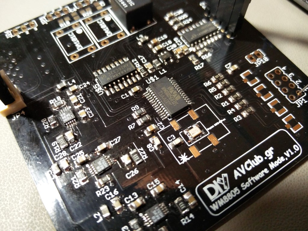
In populating the board I started by soldering on the power supply components. The LT3042s are pretty fine pitched. Some sort of magnification is definitely necessary when soldering them.
Before soldering on the rest of the components, I made sure that the power supplies were outputting the proper voltages.
I then proceeded to solder the rest of the components. The NDK oscillator in particular is especially tiny – it should be handled carefully.
Next up was the software. With a little Googling I came up with several candidates, either in the form of ready-made Arduino libraries or pieces of code. I ended up basing my code on this project. If you choose to build a wm8805 based receiver you really should read up on it. There is a lot of valuable info there.
My code was tested by connecting an old UNO to the wm8805. Like I said, that is OK to do because the isolator also does level shifting from the 5V of the UNO to the 3.3V required by the wm8805.
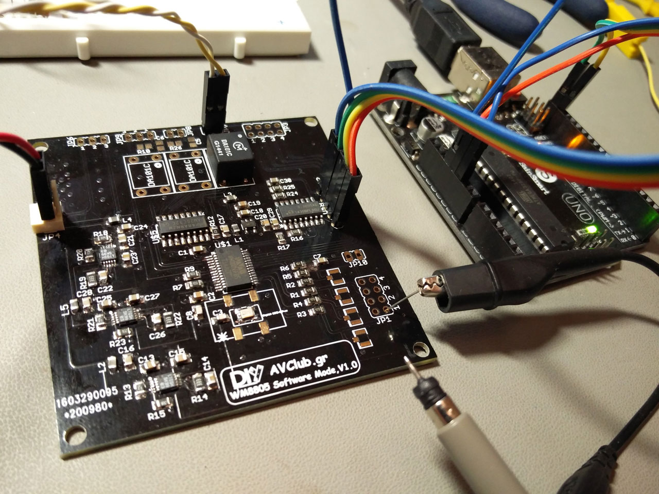
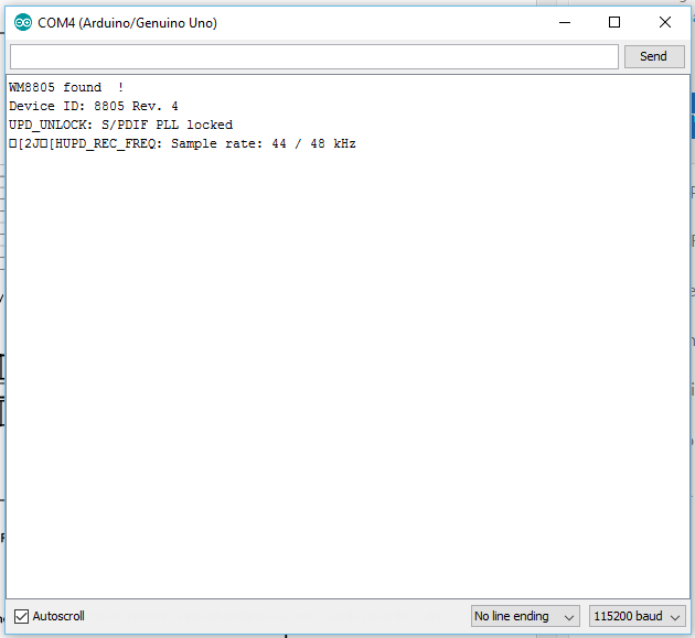
This is my first attempt at a piece of working code.. We have a lock! 🙂
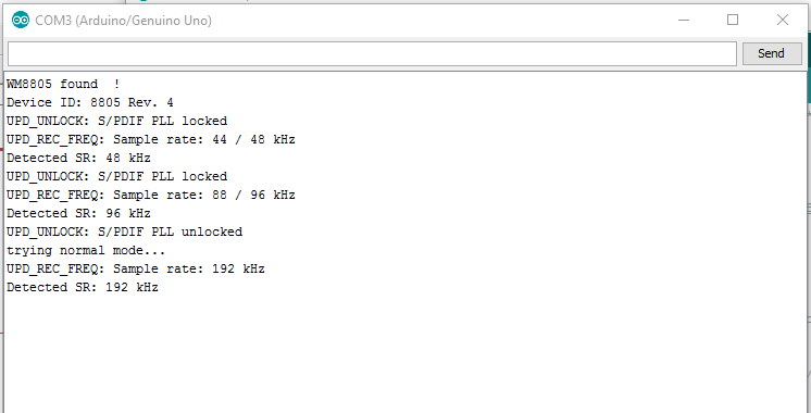
In the original code’s writeup, you may have noticed that the wm8805 had a hard time differentiating between 44.1KHz and 48KHz, 88KHz and 96KHz, and between 176.4KHz and 192KHz. I tried to go around that by reading Register 16 (Indicated Sampling Frequency, according to IEC 6095-3). This works just fine if the s/pdif signal is flagged as a consumer signal, but may not work properly for professional type signals. That is due to the WM8805’s “consumer” “personality”. It does not mean that it won’t lock to such signals. It just won’t properly display the detected sampling rate.
One more thing. I haven’t needed to incorporate this code into a working project just yet, so there are things missing, such as a proper way to change the input, but they should be trivial to incorporate into the code.
With these caveats, this is my code (v0.82): WM8805_control_code (3875 downloads )
v0.82 11/04/2017:
- Initial public release.
- Only usable through serial port.
- Outputs detected sampling rate.
- Input switching only through editing the code (lines 326 – 334).
- Constantly (every 100ms) checks the status register, so is essentially blocking. Could be made to check the register once every (for example) 500ms.