
The Soekris dam1021 has a serial port (J10).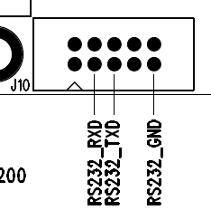
This serial port serves a number of purposes:
1) It is used for uploading firmware updates via the uManager prompt.
2) It is used for uploading filter values via a software utility (not yet released).
3) Outputting info on currently selected Input, Sampling Rate and Volume level.
4) Controlling things by receiving commands. Up to now, we can select Input and change the Volume. More commands might be added in the future (or already exist, but are not yet documented by Soren).
In order to do all those things, one has to interface to this serial port. In this post I detailed how to interface a computer to this port (so as to perform a firmware upgrade). Now it is time to do the same for a microcontroller, say an Arduino.
The problem is, microcontrollers use different voltage levels compared to the “classic” RS-232 serial protocol. In order to make these different things talk to each other, we need to use what is called an “RS-232 Receiver / Transmitter” IC. Such ICs are pretty commonplace, since they are found inside of most devices that come with RS-232 interfaces. The “classic” IC that is used is the Maxim MAX232. It is very low-cost but it is also an old design, requiring 5V (instead of 3.3) and 5 x 1μF capacitors. There is a much newer version of the chip, the MAX3232, operating with a voltage between 3V and 5V and requiring much smaller caps (0.1μF), but it is not as widely available as the MAX232. Since I was in a hurry to get things up and running, I chose what I could find locally in stock: a MAX232.
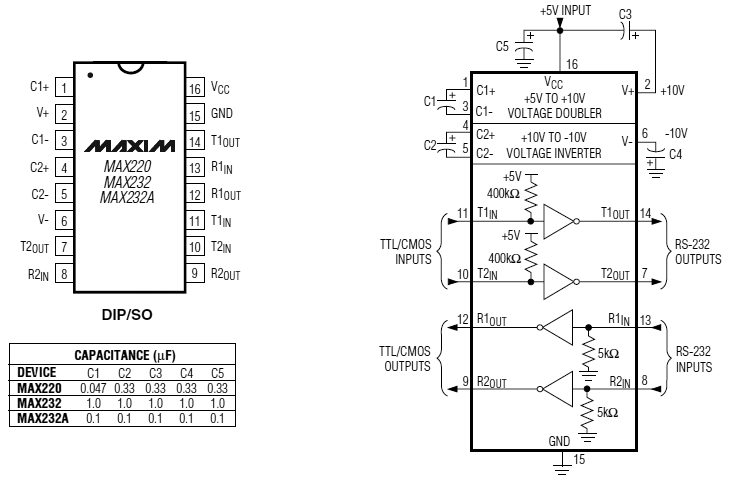
This meant that I had to power it with 5V and use 1μF tantalum or ceramic capacitors, but what the heck. I was in a hurry.
After reading the MAX323’s data sheet I ended up with this:
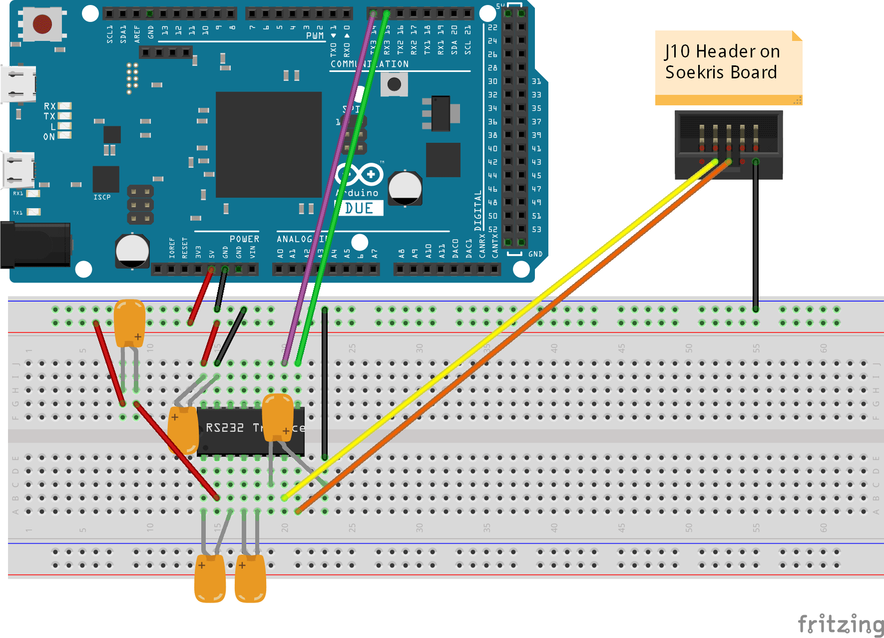
(click on the picture for a higher resolution version)
You will notice that I am using Serial3 of the DUE to talk to the DAM DAC. Any serial port could be used, but I chose Serial3 because it was practical – it will be easy to route these specific pins on the shield that I am designing.
Once I verified that the above circuit worked, I built it on perfboard to keep handy:
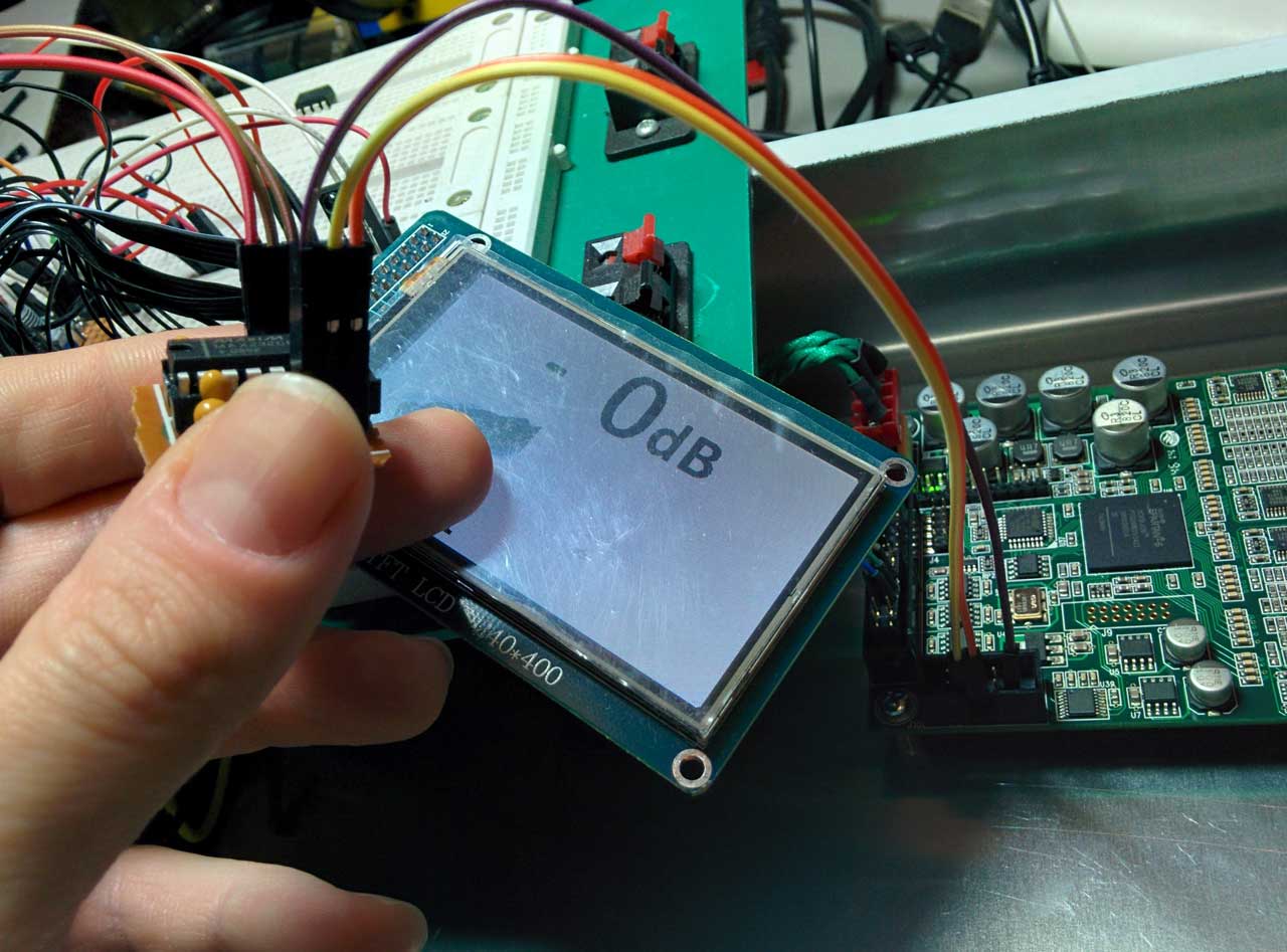
The above circuit works in general but has some trouble with the DAM DAC. It works just fine upon power up but at some point loses communication with the DAC. The only way to restore communication is to power cycle the DAC. I am not sure what the problem is, but I suspect that it has to do with the power management features of the ICL3221 chip used on the DAM. I have ordered an ICL3221 to use in place of the MAX232, in hope that everything will work fine when I use this (at least in theory) fully compatible IC.
Stay tuned.
What about using level converters? Also, what is the purpose of the TXD and RXD pins in the isolated area of the 26-pin DAM header? Could they be the ‘always on’ means of serially interfacing? Been meaning to ask Soren this.
Level shifting wouldn’t work because RS-232 requires negative voltages as well as positive: “Valid signals are either in the range of +3 to +15 volts or the range −3 to −15 volts with respect to the ground/common pin;”. The MAX232 has an internal DC-DC converter (voltage pump) that generates the necessary voltages. Regarding the isolated RX/TX lines, I don’t plan to use them since using them would mean sharing a common ground between the Arduino and the USB to I2S interface. I am designing a shield that has isolation between the Arduino and the MAX232 (or whatever).
Thanks for the clarification. Do you plan on making the shield available to the community? to purchase, that is, not just the files.
I may have a few PCBs to spare, since I will probably be placing an order for 10 boards (and obviously not needing all of them). But they will be just the bare PCBs and I will not be making a profit.
Hi Dimdim,
I am also following your code with DUE. Please put my name on one of them also!
I’m designing front panel. I think there are 3.2″ lcd, volume, input selector, and phone jack. What do you think about front panel?
Cheers,
Sean
OK Sean, I got you down for one too. For the front panel, you will need space for the 3.2″ TFT, for one rotary encoder and for the IR Receiver (plus whatever else you need, besides the Arduino stuff). At the moment the same rotary encoder takes care of both the volume control as well as the input selection but I plan to change that to separate rotary encoders.
Thanks for the shield 😉
Yes, I like to separate rotary encoders.
Btw, if arduino use serial port of DAM’s J10, how to update firmware or filter for FPGA with PC?
I’m working on that, and I think that you will like my solution.. 🙂
Please put my name on one of them! I am ordering a Due in anticipation of your code so you’re under the DAM gun, so to speak!!
I hooked the DAM to a Raspi via the Raspi’s i2s and running Volumio with the Hifiduino ESS K2M i2s settings and it sounded really good. Running one of spzzzzkt’s filters, no interface just the i2s and using a regulated PS into J2 was a significant improvement on the out-of-box filter and a USB interface.
OK Derek, I got you down for one board. I too have hooked up the RPi to my other DAC (the Buffalo) via I2S and it was pretty sweet, but I chose to go the USB route due to the problematic clock of the RPi.
Regarding the power input to the DAM, I’m building a Salas BiB to power it.
Thanks re reserving the board. I suspect the good sound of the RasPi and the DAM might have a lot to do with Soren’s DAC reclocking the data – thus taking care of the compromised Pi clocking.
Nice PS, the Salas. A tip, given by BlgGear, is to not use the GNDs on J2 as the traces are quite thin but connect your PS ground to J1 GND.
Yes, the FIFO probably has something to do with the good sound. I will give it a try myself, even though the purist in me will be screaming in agony.. :p
I saw hifiduino’s comment on the GND on J2 and I must admit that I was surprised. I would have expected the GND to have been connected to the ground plane layer. Anyway, I plan on not bypassing J1 for the moment.
Worth a try, the Raspi and DAM. Surprised me – pleasantly.
Am trying to get Punky’s Voyage Mubox for the Raspi to work as I used his Voyage MPD happily for a few years with an Alix board. While the Volumio plays fine with the DAM I have not been able to get the DAM recognized by Voyage Mubox.
And yes, I reverted to running from the ‘correct’ input terminal as well. Will try the diyinhk bipolar through there as well. Meanwhile I’m using a little 7V dual secondary trafo that Richard Sumner wound for me to match the odd 117V 50Hz supply where I live.
FWIW, got the Voyage MPD working on the Raspi with the DAM. Need to compare it to Volumio over a few days but first impressions very good. Leaner build than Volumio with the 3.18 kernel.
Hello dimdim, i will wait for you to solve the communication problem :). Is your shield compatible with UNO?
Hi there Mr. HiFiDuino!
I haven’t given up on the problem with the serial port, but I have put it on hold while I put the DAM in a nice enclosure. I should resume work on the serial stuff in a few days.
I’m sorry, but the shield will not be compatible with the Uno since it will require more I/O. It’s a good thing that DUEs go for ~16-17€ on Ebay nowadays.
Didim, if available I would be interested in your board as well. Please keep me in mind if still available.
Thank you
AR2
Hi Didim,
Is it possible to update firmware by Arduino?
Thank you,
Brant
AFAIK no one has done it.. I don’t think it would be particularly practical. You’d need a way to get the firmware to the Arduino, which would mean using an SD card or something.. so if you’re going to go to so much trouble, you could just hook the dam up to your computer with a serial cable and adapter.
The image doesn’t exist.. please reuploaded, will you ? I am interested to know it more