
Please note that this page is now essentially obsolete, due to the new Universal Isolation Shield, but I will keep it up as reference for those who have built the old shield.
This is the page for the TFT HiFiDuino Shield, a companion to the TFT HiFiDuino Code.
It is a compilation of material from several posts that I have made over the last couple of years, relevant to the shield that I have designed.
This is what you need to know in order to build my Buffalo Shield.
First of all, here are the DipTrace files (schematic & PCB): Buffalo Shield v.1.1 for TFT HiFiDuino (schematic & PCB) (13465 downloads )
And here is the relevant build & wire guide: Buffalo Shield v.1.1g for TFT HiFiDuino (documentation) (9364 downloads )
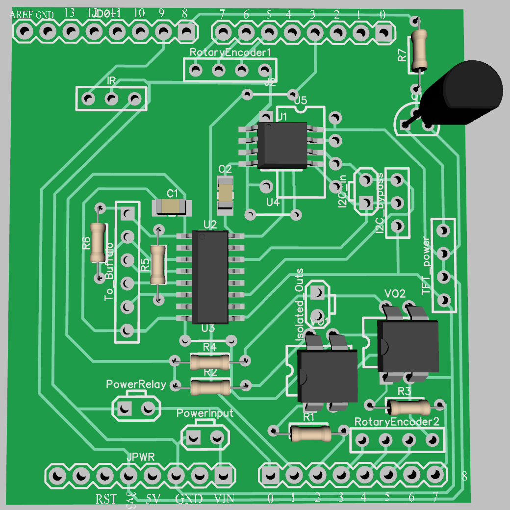
This is what DipTrace thinks the board ought to look like:
And this is what it actually looks like:
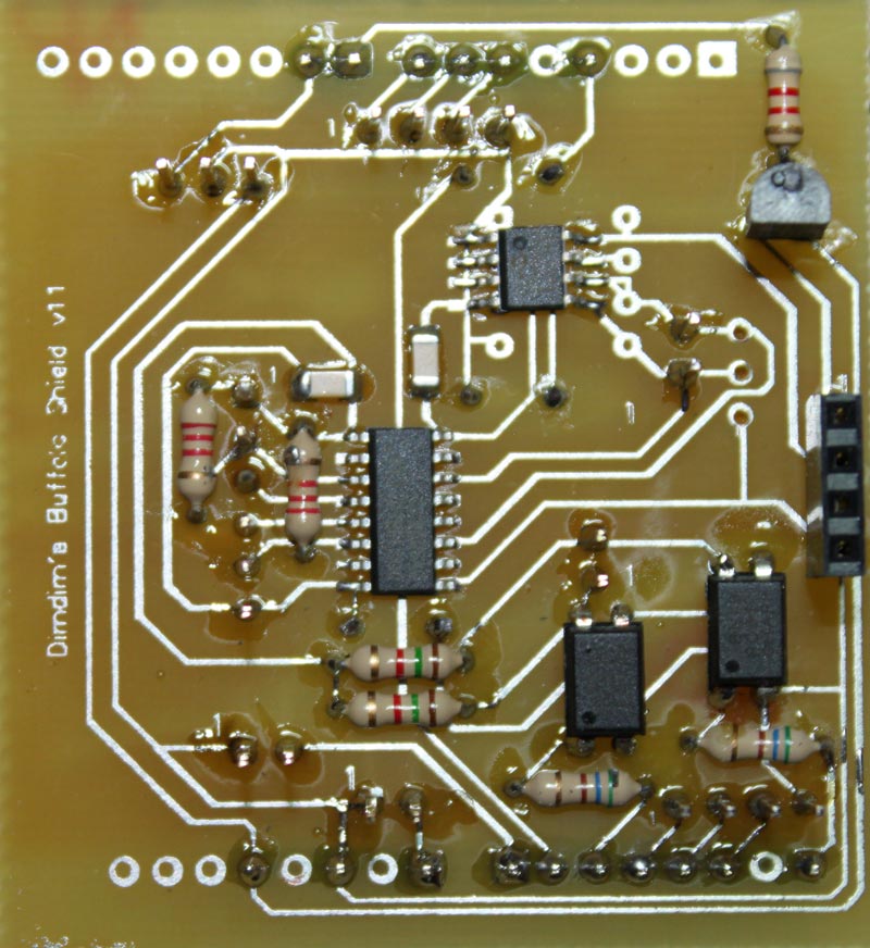
Close enough..
This shield features:
– Galvanic isolation for the I2C signals as well as 2 digital outputs (Arduino -> Buffalo) and 1 digital input (Buffalo -> Arduino).
– EEPROM chip (24LC256) either in SMT or DIP footprint.
– Backlight control for the TFT through a PWM-controlled transistor.
– Headers for two rotary encoders.
– Output for power relay (for remote on/off).
– Header for IR receiver.
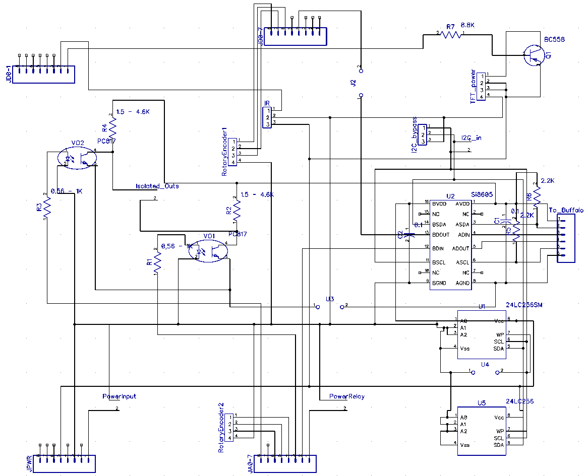
This is the schematic for the shield:
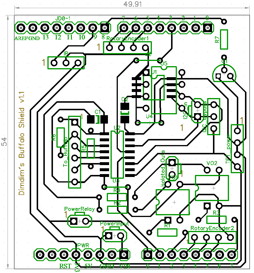
And this is the resulting PCB:
This is a description of the various headers:
IR: Use a standard 38KHz IR Receiver Module, like the TSOP4838.
1: Signal (Pin 9)
2: GND
3: 3.3V
RotaryEncoder1: Use any simple rotary encoder.
1: Left pin (Pin 7)
2: Right pin (Pin 6)
3: Selector pin 1 (Pin 5)
4: Middle Pin & Selector pin 2 (GND)
RotaryEncoder2: Use any simple rotary encoder.
1: Left pin (Pin A3)
2: Right pin (Pin A4)
3: Selector pin 1 (Pin A5)
4: Middle Pin & Selector pin 2 (GND)
I2C_In:
1: SDA
2: SCL
(note: this is the I2C connection to the Arduino. SDA should be connected to pin 20 and SCL to pin 21)
I2C_Bypass:
1: GND
2: SDA
3: SCL
(use this if / when an isolator IC (U2) is not used to send the I2C signal to the Buffalo)
Isolated_Outs:
1: Out 1 (Pin A2)
2: Out 2 (Pin A7)
TFT_power:
1: TFT Backlight LED (dimmed by Pin 8)
2, 3: 3.3V (for TFT power & pin RD)
4: GND
PowerInput:
1: GND
2: Vin (8V-12V)
(connect here the power supply to the Arduino)
PowerRelay:
1: GND
2: 3.3V out (Pin A0) in case of Due, 5V in case of MEGA
(connect here the power relay that powers on the DAC. Note: this pin can source at most a few mA of power, so you will need to use a transistor that will in turn drive the relay)
To_Buffalo:
1: Buffalo Vcc (3.3V)
2: SDA
3: Sidecar Control (Pin 3) (See note below!)
4: Lock LED input (Pin A1)
5: SCL
6: Buffalo GND
Note: The Sidecar has its control pin at +5V potential, so if you connect it directly to the header it will damage your isolator’s output pin. You should use a transistor to “buffer” the Sidecar control pin. I’ll put up a (very simple indeed) schematic when I get the chance.
The shield “as it” supports the Buffalo III board. In order to support the newer Buffalo III SE board, a slight modification is to be made:
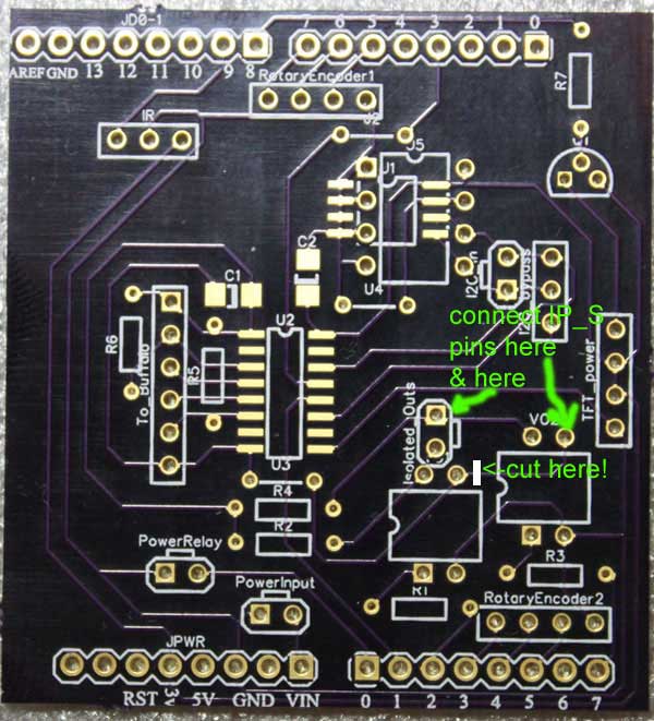
The idea is to connect the photosensor side of one of the optoisolators directly to the IP_S header on the B3SE. In order to do that, you will have to cut one trace on the PCB and solder directly onto one of the optoisolator’s pins. That’s pretty much it.
Note: There have been some reported cases of the DUE & shield not functioning properly, i.e. not starting up or taking too long to start-up, exhibiting “sluggish” behavior, etc.
In most cases this is due to EMI / RFI. The solution is pretty simple – just clip a ferrite to the DC cable going into the shield.