
These days I’m co-developing an AK4490 based DAC. The aim is to end up with a no-compromise dual mono design, one that would perform at the very least on par with my Buffalo III.
Of course, to do that one has to run the 4490s in software mode.
As a matter of fact, it is generally preferred to run a 4490 in software versus hardware mode, for several reasons.
To begin with, in software mode the 4490 supports DSD decoding. It goes as far as to support a “Volume Bypass” feature which bypasses most of the processing done on the DSD signal (a.k.a. “the ΔΣ modulator”), resulting in more pure sound. But of course we do lose the ability to do volume control in software.
Software mode also allows us to try out all of the supported SQ features, like the different “Sound Setting” modes.
At last but not least, we get digital hardware volume control.
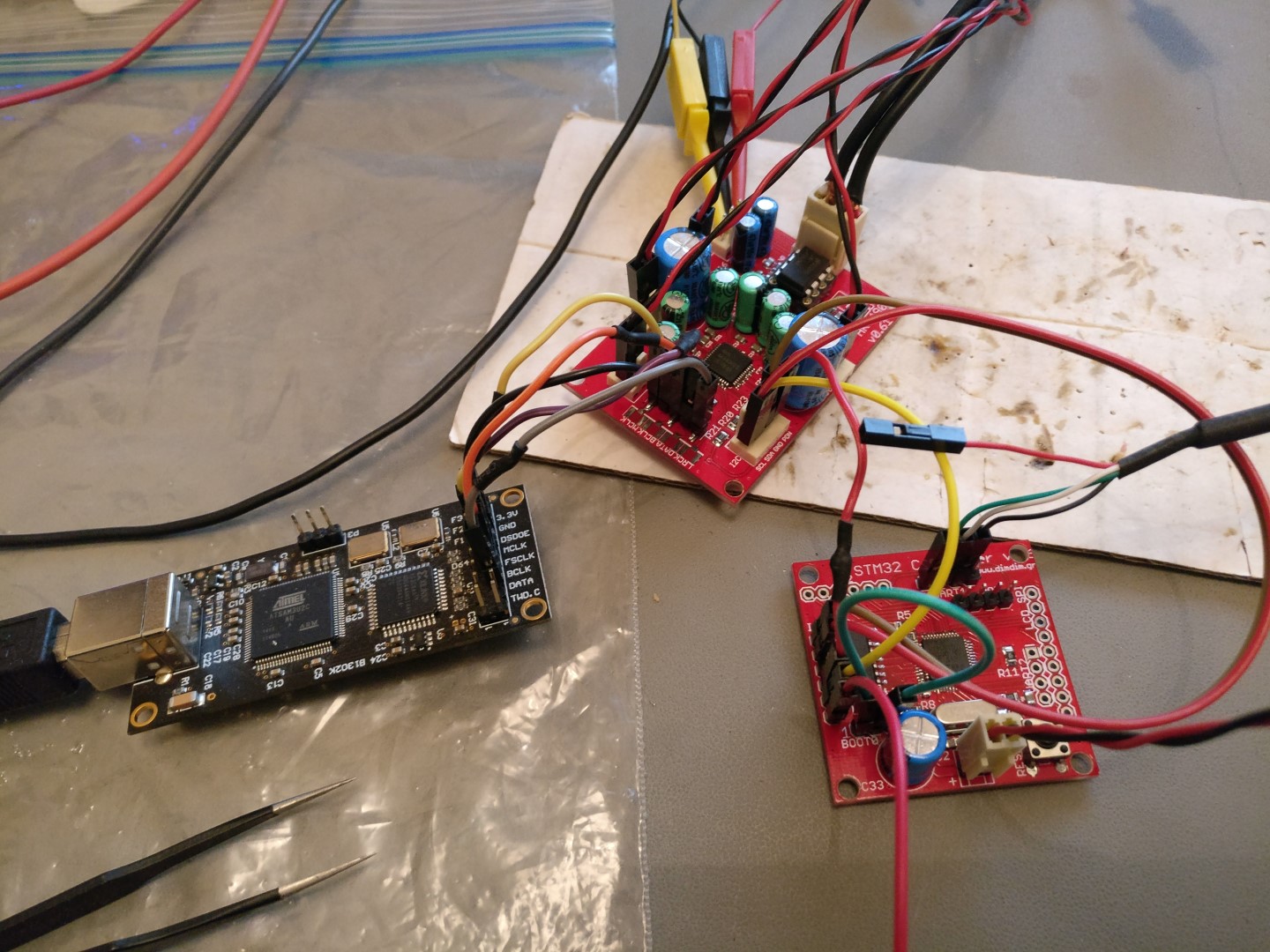
This is the prototype that we designed, getting I2S input from an Amanero and being controlled by my custom STM32 controller (more on that in the near future).
I searched the Net for any ready-made code that would control the 4490, but I couldn’t find anything worthwhile, so I began virtually from scratch.
So, my Arduino code (a.k.a. “aKduino”) enables:
- Controlling an AK4490 through the I2C bus.
- Automatic switching between PCM and DSD. It does rely on getting a “DSD type signal” from our USB-to-I2S interface of choice. The 4490 by itself is not capable of determining whether its input is PCM or DSD.
- Setting the volume (in 9 steps.. just to confirm that volume control does indeed work).
- Selecting “Volume Bypass” for direct DSD processing.
- Selecting the internal DSD filter’s cutoff frequency (50KHz or 150KHz).
- Selecting one of the 4 available PCM filters.
- Enabling or disabling the Super Slow filter.
- Selecting one of the 3 available “Sound Quality” settings.
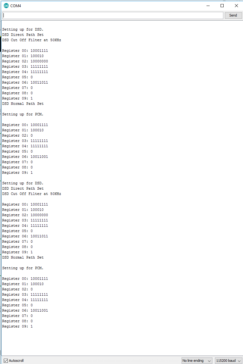
- Displaying all of the registers’ settings (for troubleshooting purposes).

Software Requirements:
- Nothing (for now)
Basic Hardware Requirements:
- Any Arduino (*)
(*) I should note here that the AK4490’s datasheet states that all of its I/O pins are expecting 3.3V logic levels but there has been a large number of reported cases of 5V Arduinos working without problems. I’m too much of a coward to try that myself so I used level converters for my initial testing and eventually a custom STM32 board that uses 3.3V logic but you may want to try your luck with 5V logic levels. Just don’t blame me if your 4490 gets damaged in the process.
Currently the code is at v1.35: aKduino Code (488498 downloads )
Here is the revision history:
v1.35 20/12/2016:
- Code cleanup for first public release.
v1.33 19/12/2016:
- Added full control of sound parameters through serial port.
v1.27 18/12/2016:
- First functional version.
- Automatic switching between PCM and DSD by monitoring DSDPIN.
One more interesting project ! I will surely be interested to try if all goes well and if you are making more of these.
Am seriously considering Rpi with Kaali and either Hifiduno or such HAT DAC.
So if you can shed some light on the Vis-Vas with your current project would be very glad.
The results that I am getting are very encouraging. Right now I’m building a second unit to try dual mono. The real challenge is the output stage.
Thanks for the reply, I will look forward to the completion of this project.
Yes output stage will be crucial ! What do you recommend for the same ??
Would a Tube Buffer work better ???
Analog electronics are not my forte, so I’m waiting on help from people better qualified in this area. What I do know is that the 4490 outputs a lot of DC at its output, and there is a need for gain, so a pure buffer won’t cut it.
I have the same project. I controle the dac with i2c bus but i can’t display the sample rate ( 96khz , 192khz…) if you have an idea, I will be delighted.
I’m afraid that I haven’t yet found a way to determine the sampling rate. It seems that this chip just doesn’t support it.
I have a similar project based on a XMOS U216-512-TQ128-C20 and the AK4497EQ where register settings are compatible with the AK4490EQ, with the USB Audio 2.0 libraries we get all information concerning the sound to be played PCM, DSD, Frequencies, Bits.
I too have been meaning to get involved with XMOS development. The idea of having the USB receiver on the same PCB as the DAC chip(s) is very appealing.
From your experience, what kind of learing curve should I expect? Regarding the software part of the endeavor, the hardware part is easy for me. I suppose that everyone is following a reference design.
This USB Audio 2.0 library is included in the SDK, right?
Have you made any info on your project public? I would love to read about it..
I don’t put currently anything public, the base source is delivered by XMOS , some litle change as to be done to switch the PCM and DSD mode (realy specific by AKM DAC chip) and remove the PLL clocking part if not used. And adjust / upgrade to cover the PCM 768khz and DSD 512 (256 for the AK4490) if you use Quartz of 45/49 out of the standard one 22/24 (rounded :))
On the knowledge base C programming under an Eclipse environment delivered by XMOS (XtimeComposer) very usefull , but clearly some time for some testing of setting the Arduino is quicker. But i never see something like the XMOS really able to work in realtime with multiple data I/O , the one a use is a 16 logical core on 2 cores real better than a CPU like ARM or other know microcontroler
Interesting.. Did you buy an official development board or did you build one from scratch?
Have you tried hand soldering the U216-512-TQ128-C20 ? It looks to be pushing what can be done by hand..
I am working on a 4 layer PCB integrating the power supply (Ultra low noise) + Xmos USB + dual AK4497 + head phone amp + line out balanced/unballanced + spdif IN/OUT . For the base development i use the DIY module sell by diyinhk that respect most of the reference design.
For soldering i buy a IR oven and hot air gun, with the hot air gun was clean and fast done for the AK4497EQ.
I realize also that some sample rate like 352.8khz and 705.6khz are missed from the datasheet of this AKM DAC chip, when you don’t have an UAC2 interface where you get from host all information about the data to be send you should work with a data buffer and analyse the incoming data flow to extract the bit lenght and frequencies before sending to AKM DAC chip over I2C where you set it to auto PCM mode ( else you could over the know incoming information set the PCM speed /depth manualy)