Since there has been a lot of interest in my Isolator shield these past few months, I have been optimizing its design.
The result of this optimization is this PCB:
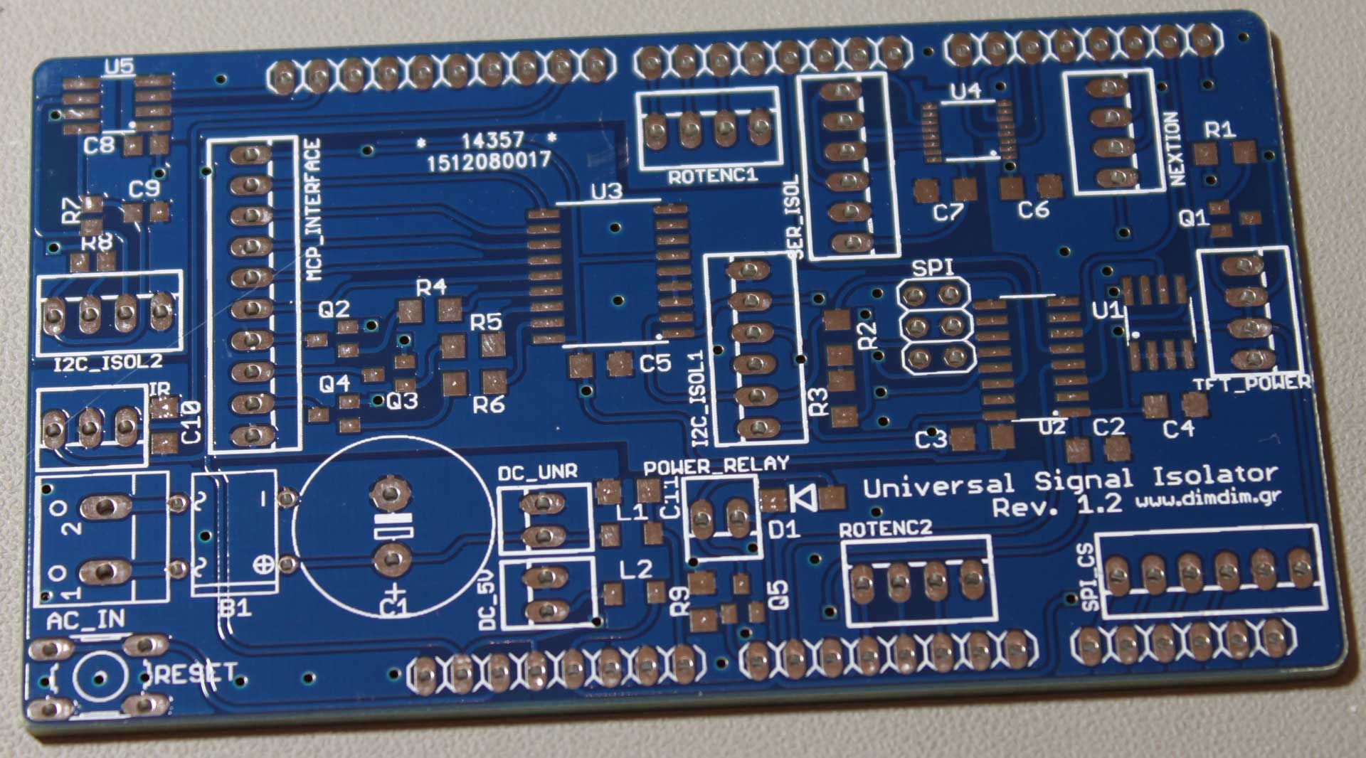
It’s called “the Rev. 1.2”.
Nothing major has changed. The pinouts are still the same, the major components are the same, the functionality is essentially the same.
The changes are as follows:
- New SPI header. It just passes through the SPI signals, nothing more. It does not connect to anything on the board.
- New SPI_CS header. Useful only if / when connecting SPI peripherals.
- Reset button. Because you never know..
- New circuitry for the POWER_RELAY header. It now uses a MOSFET and it includes a diode for the reverse current coming back from the relay’s coil.
- Decoupling cap for the IR receiver. Not absolutely necessary, but good to have.
- More decoupling for the DC_UNR input.
- Ground planes. Lower Arduino noise, at least in theory.
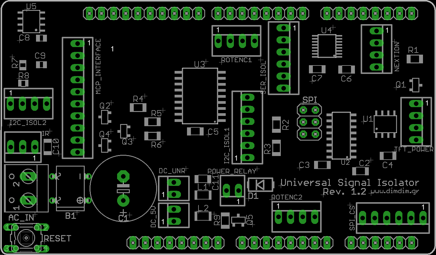
Here is the updated parts placement:
And this is the updated BoM:
PCB Part | Value | Notes |
---|---|---|
U1 | 24LC256 SO-08 | EEPROM chip |
U2 | Si8605 SOIC-16 | I2C Isolator |
U3 | MCP23008 SO-18W | 8 input/output port expander |
U4 | Si8642 QSOP-16 | Serial port isolator |
U5 | ADUM1250 SOIC-8 | I2C Isolator |
Q1 | BC856, BC808 or other equivalent PNP SOT-23 | TFT backlight control |
Q2 | BC856, BC808 or other equivalent PNP SOT-23 | port expander transistor |
Q3 | BC856, BC808 or other equivalent PNP SOT-23 | port expander transistor |
Q4 | BC856, BC808 or other equivalent PNP SOT-23 | port expander transistor |
Q5 | AO3400 or other equivalent N-Channel MOSFET SOT-23 | power relay mosfet |
B1 | Bridge rectifier 1A DB107 DIP-4 | |
C1 | 1000uF 16V | |
C2 | 100n 1206 | |
C3 | 100n 1206 | |
C4 | 100n 1206 | |
C5 | 100n 1206 | |
C6 | 100n 1206 | |
C7 | 100n 1206 | |
C8 | 100n 0805 | |
C9 | 100n 0805 | |
C10 | 100n 1206 | |
C11 | 100n 1206 | |
R1 | 8.2K 1206 | |
R2 | 2K 1206 | pull-up resistor (optional) |
R3 | 2K 1206 | pull-up resistor (optional) |
R4 | 5.1K 1206 | |
R5 | 5.1K 1206 | |
R6 | 5.1K 1206 | |
R7 | 2K 0805 | pull-up resistor (optional) |
R8 | 2K 0805 | pull-up resistor (optional) |
R9 | 8.2K 1206 | |
R10 | 10K 1206 | |
D1 | 1N9001 DO214BA | |
L1 | Ferrite Bead, low DC resistance, 3216 | |
L2 | Ferrite Bead, low DC resistance, 3216 | |
Reset | PCB-mount momentary switch |
Soon I will update the shield’s page with the new info.
Pingback: Universal Signal Isolator Shield Update, now Rev 1.2 #Arduino #ArduinoDue « Adafruit Industries – Makers, hackers, artists, designers and engineers!
Pingback: Universal Signal Isolator Shield: Rev. 1.2 – High Voltages News