
This is the home page for the ArDAM1021 Project, an attempt at controlling the Soekris dam1021 Sign Magnitude R-2R DAC by an Arduino.
First, a little background info.
This is the Soekris dam1021 R-2R DAC:
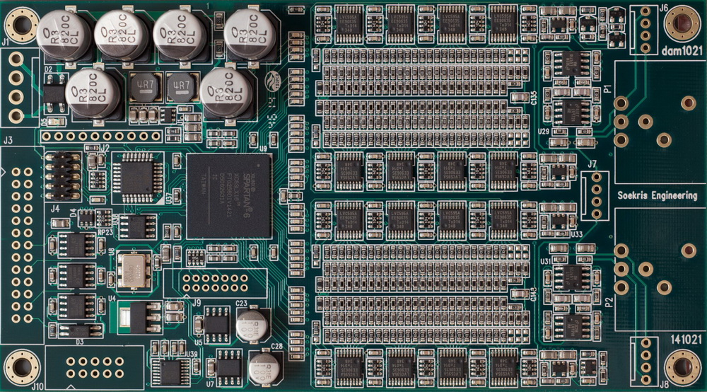
It supports three digital inputs (Coax & Optical S/PDIF and I2S), high precision digital volume control and the uploading of user-generated filters. It is possible to access these features by using the dam’s built-in serial port. However, IMHO connecting a computer and typing at a keyboard is not the most practical approach for controlling a DAC, so I decided to make a “dam1021 edition” of my TFT HiFiDuino code.
The code is currently at a Beta stage, meaning that it is functional but not complete. Still, it performs the basics:
- Controls the volume.
- Switches between the two supported s/pdif inputs, as well as the I2S input. Also enables auto source selection.
- Switches between the four supported filters.
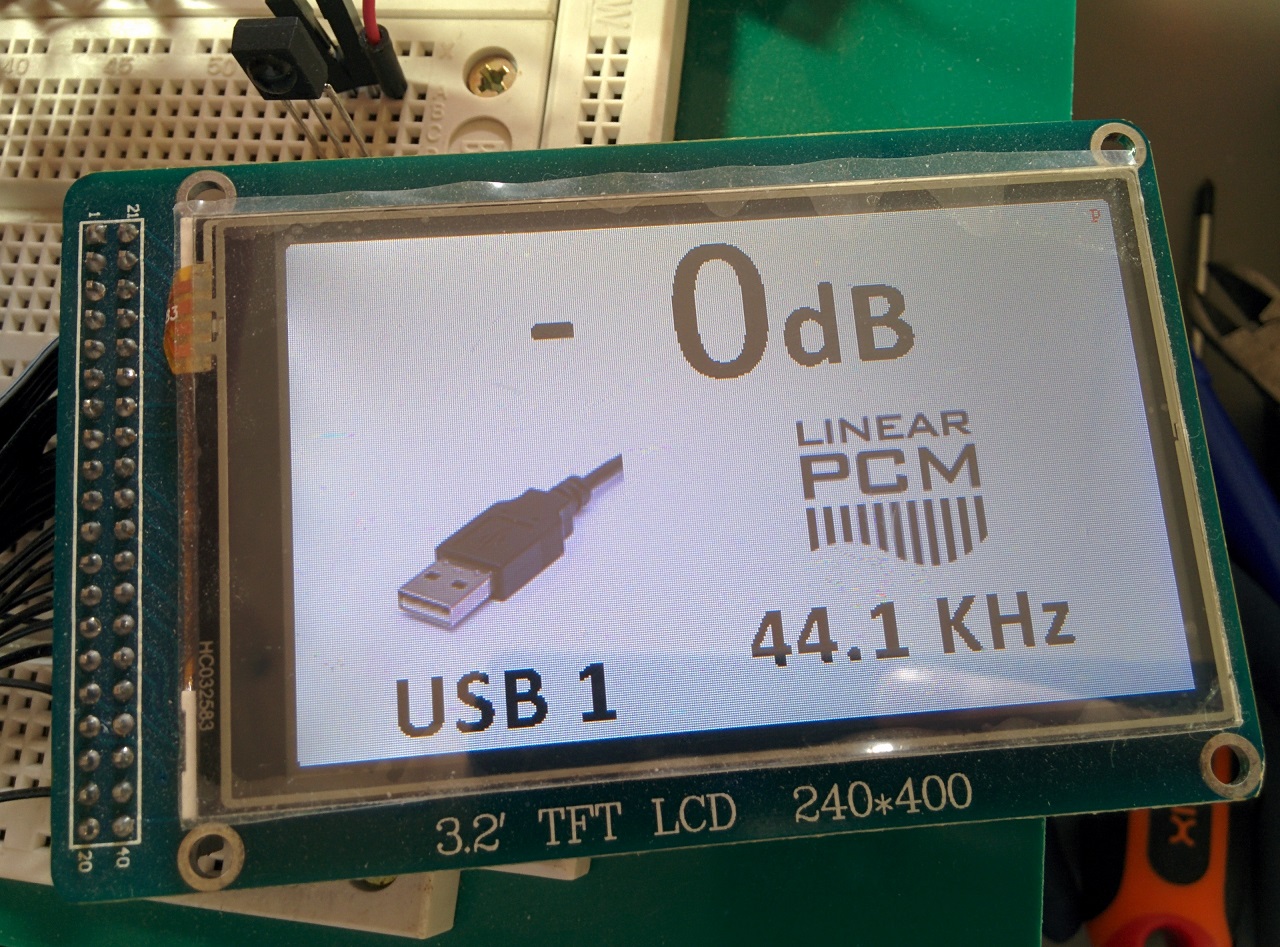
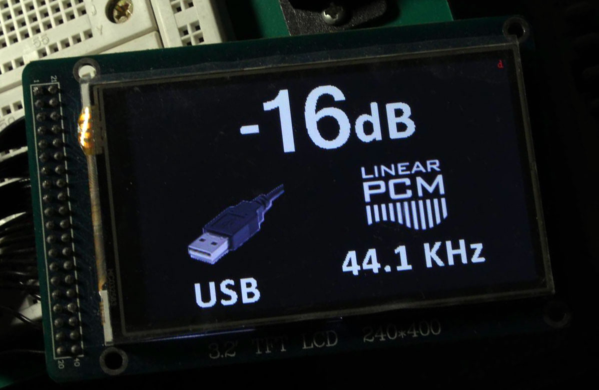
- Displays incoming signal sampling rate and type.
- Supports full IR remote control functionality. Supports a large range of remote manufacturers.
- Minimal display mode as default. Goes into full display when changes are to be made to parameters.
- Full graphics support in the minimal display.
- Supports either white text & graphics on black background or black text & graphics on white background.
- Option to set 0db as default (power-on) volume for connection to a preamp.
- Remote power on/off functionality (or always on – configurable in the code).
Currently the code is at v0.74: ArDAM1021 Code (164806 downloads )
Software Requirements:
- UTFT Library
- UTFL_DLB library
- Adafruit MCP23008 library
- Arduino-IRremote-Due library
- RotaryEncoder library
- Fonts (included in the ZIP file)
- Graphics (included in the ZIP file)
Basic Hardware Requirements:
- Arduino Due
- 3.2″ TFT with resolution of 240 x 400, compatible with the UTFT library
- Rotary Encoder
- IR Receiver
- Compatible IR remote control (Apple Remote or other)
The fonts should go into your UTFT & UTFT_DLB directories, usually found in the Windows user’s Documents folders (for example, here: c:\Users\<user name>\Documents\Arduino\libraries\UTFT_DLB\).
The bitmaps should go into your sketch’s folder.
You should keep in mind that this code is designed to be used with the Universal shield that I have developed for this purpose. The shield has its own page: Universal Signal Isolator shield for the Arduino DUE
However, this shield is only really necessary if you need filter selection memory (the code saves the selected filter / input to the EEPROM). This new Universal shield will also take care of the serial connection to the dam (with isolation) but that can be done easily without a shield (if you don’t want galvanic isolation): just connect three wires from the DUE to the isolated serial port of the DAM (enabled since firmware v0.99). You need to connect the DUE’s TX3 and RX3 respectively to the DAM’s “ISO RXD IN” and “ISO TXD OUT” pins. You also need a wire connecting the DUE’s GND to one of the DAM’s “ISO GND” pins.
Here is the revision history:
v0.74 19/08/15:
- Changed the rotary encoder code. Now it works exactly as it should.
- Various serious bugs fixed (vol control etc).
- New status: Beta
v0.63 19/08/15:
- Added support for white text on black background. Added the necessary graphics.
v0.58 18/08/15:
- Added code to support selection of the 4 available filters (via remote or rot/enc).
- Changed the number of inputs to the built-in 3 (plus Auto).
- Some code cleanup. Still very Alpha..
v0.50 31/07/15:
- Code cleanup. Still in Alpha condition.. Preview release for dimdim.gr.
v0.30 11/02/15:
- Added code to select inputs. Last choice is the Auto Detection function.
v0.25 08/02/15:
- Added code to read from Serial and display sampling rate.
v0.21 05/02/15:
- Tested with actual DAC. Confirmed proper operation of volume control.
v0.20 25/01/15:
- Serial out through Serial3 implemented. Outputs volume control codes. Not tested with actual DAC.
Hello, thanks for your info.
So suppose adding a TTL->RS232 adaptor, this whole thing should work?
Yes, it should and it does. The problem is that it is not totally reliable – the serial communication breaks down after a while, but that is not because of the code or the Arduino. See here, towards the end of the post.
May be it’s due to the power saving feature of the RS232 receiver onboard, just guess. Hope the firmware of dam1021 could fix this problem later.
That’s what everyone is guessing.. I really hope that these problems do not apply to the isolated serial port.
Hi Dimdim,
The code have been running many hours now on my soekris V0.99 on the real RS232 without stopping. Did it stop often? It might be fixed in 0.99…
I will be waiting for the next version with filter select? 🙂
best,
Paal
Hello Paal!
The code usually stopped working after a few minutes. By working I mean sending commands to change volume or switch inputs.
It is really good news that v0.99 fixed the RS232 port as well!
I’ll do my own testing probably tomorrow..
I am also officially resuming work on the code. 🙂
I can confirm that my Arduino is also behaving quite nicely with the new firmware – no more lockups with the RS232 port! 🙂
Tomorrow I’ll check the isolated port.
The isolated port indeed seems to be working just fine. 😀
Good news to hear!
Hi DimDim,
First of all, I am totally new to this Arduino thing, I am following this page to try to make the LCD remote control broad for the dam1021.
On software side, I downloaded all the files in this page, then downloaded the Arduino IDE (version 1.6.5), connected Due (programming port) to Windows7 64bit, opened the IDE, the first time I compile the INO it shows error in SerialUSB, then I realized that I need to d/l & installed SAM Broad files. after that I retry and it works. Now the INO has been compiled and uploaded to the Due I suppose.
On hardware side, I have done the shield with components soldered, for some resistors you told a large range of resistance value that I am little bit worry but I still manage to solder resistors in the range.
My question is:
1. The shield should be connected to the Due via the pins, I soldered some (refer to the photo in manual) but I solder a bit more than that shown in photo, is it okay?
2. If that’s ok, then I suppose I just connect the two broads together like the photo shows (with the encode rotary, IR receiver), where should I give the power? how many volt in DC should I provide? There’s a “power in” on the shield but it doesn’t tell how many volt… Or should I just gives 5V to the DC in jack of Due?
Thanks a lot.
In addition to Q2, according to http://www.dimdim.gr/arduino/tft-hifiduino-shield/
It says, “PowerInput” requires 8-12V DC. Is it the ONLY power supply that is needed when connecting Due+Shield+LCD?
Thanks.
Hi there Obee,
1) It’s OK if you soldered more pins than just the necessary ones. They can’t do any harm.
2) There is a number of things you can do to power the DUE. The simplest thing to do is to just use USB power. It’s perfect for testing things etc. For a more permanent solution, you either give it 5VDC through the DC jack of the DUE or 8-12VDC through the Power_Input pins on the shield. The Build & Wire Guide for the shield covers this.. http://www.dimdim.gr/download/419/
But you really don’t need to build this shield to control the DAM. At the moment you can do the job just by hardwiring everything to the DUE headers. Plus, I’ve designed a new shield that takes care of the serial connection to the DAM (among other things). I posted about it a few hours ago.
Thanks Dimdim,
About “hardwiring everything to the DUE headers”, AFASIK, it just provide some basic functions like volume control, (manual/auto) input selection. I would like to have display (LCD) showing status like SR, input, volume; remote control that can do on/off. Am I right that it needs help of the shield (not just Due alone) to make the requirement above happens?
Because I am little bit confuse the purpose of the shield, as the DUE stores the program code and it can talk to DAM via serial communication, the DUE can also light up LCD, read IR signal, and control devices such as relay.
One more question, how to connect the LCD? To the shield or to DUE? I can’t find from your guide about the connection. Thanks again for your prompt and detail reply.
To be exact, you don’t really need the shield since you are not using its I2C isolation (not used by the DAM) or the EEPROM chip (not used by the code ATM, even though that is about to change with the filter capabilities that were introduced by the v0.99 firmware). All other shield functions can be implemented by hardwiring everything to the DUE (you can connect the rotary encoder, the IR receiver, etc.) but the shield does tidy things up a lot, so it’s good that you built it. Plus the next version of the ArDAM code will make use of the EEPROM to store filter settings.
The LCD will need to be connected to the DUE as per this guide: http://www.dimdim.gr/2013/11/3-2%E2%80%B3-tft-connection-to-arduino-due-update/
Thanks DimDim, very comprehensive guide!
For the shield, can we just use the memory on DUE instead of the memory on shield?
Will you write a guide for connecting DUE and the peripherals and the DAM without the shield? Given that no program code change is needed.
(continued from above)
There exists an “emulated EEPROM” library that uses the DUE’s FLASH memory as EEPROM but I don’t plan on supporting it for this project as it wears out the DUE’s FLASH. Perhaps I will use it in some other project if the specific application is not too write-intensive.
Regarding hard wiring of the DUE, DAM, etc, it is not such a good idea since it offers no isolation between the DUE and the USB interface (they share a common ground), plus the EEPROM will be necessary for the next version of my code.
Still, if you would like to do it, I think there is enough information in the TFT HiFiDuino Shield’s documentation.
Pingback: Firmware v 0.99 | H i F i D U I N O
Hi Dimdimi,
When I loaded your latest code v0,74 into Arduino IDE, it reports ‘SerialUSB’ was not declared in this scope. Understand SeriaUSB is used for debug purpose. Did I miss to load the related library for this function?
Hi there Gary,
It sounds to me like you have not selected the DUE board in your IDE.
Got it. Successfully compile the the codes. Thanks.
Hi DimDIm,
I am a new but very interested in you project Arduino with DAM1021. On the guide of DAM its said, the RS232 port has power saving mode to reduce noise. One we connect Atrduino to the port. It will active RS232 on DAM and stay for ever. Will it increase noise to DAM output?
Thanks for your great work on this project.
Kevin
Hi there Kevin, thank you very much for your kind words!
The Arduino connects to the isolated serial port of the DAM, so the RS-232 port shouldn’t power up.
Are there any ways of debugging the due and universal shield? I just connected the due and tft using the shield but the only thing I got so far is that the TFT backlight works nicely but nothing else shows up on the screen.
Are you running the ArDAM code? When you say that the backlight is working, do you mean that you are seeing a fully lit (white) screen?
Yes, I’m using ArDAM code. When I plug the power to arduino I get lit white screen as you suggested.
While you are at the white screen try pressing the Arduino’s reset button.
AHH, I feel so stupid now. Should I use this quide for connection? http://www.dimdim.gr/2013/11/3-2%E2%80%B3-tft-connection-to-arduino-due-update/
I only connected the two wires on the shield 🙂
Correction 4 wires from the shield. So i should connect the rest as well ?
Yes, you need to connect a whole bunch of wires. My guide provides a relatively fool-proof way of making the connections.
Hi, You can save data without EEPROMEEPROM. And I made a DSD compatible version base on yours, which can save volume and all settings. If it’s OK to share online, please let me know. Cheers!
Hi Dimdim, I made a version which can save data without external EEPROM base on your v0.74. Is it OK to publish it?
Hi Jimmy, of course it’s ok to publish it! That is the whole idea with these projects.. 🙂
I hope you will be OK with me “borrowing” some of your code too. 🙂
Hi Dimdim,
I found an issue with the firmware 1.05. When the dac starts, it reads volume value stored in uManager mode. However, as the arduino shall keep the volume setting as well. For example, if arduino stores -20db but the uManager stores 0dB, it will be 0dB at dac startup, until the program reset the volume as -20db.
I tried to reset the volume and finally found that the best time to reset the volume is when the serial port receives L000. I dont know is there better way, please share you experience if you have other better way to do.
Thanks
Hi Dimdim,
Can ArDAM1021 control two DAM1021s in true balance mode ?
Thanks
What ArDAM does is send commands to a serial port. If you set up your DAMs for balanced mode beforehand and then do some creative serial port connecting, you should be OK.
Hi Dimdim, thanks for the prompt reply. I’m using the auxilary +3.3V out on helper board for J3 header. The other serial (TX, RX and ground) connections from J10 to universal isolator shield serial3.
I have a strange problem with ArDam code, universal isolator shield, tft and the DAM. At the moment I only want to use the code to display the current sample rate and input. No encoder or ir connected. When The DUE is powered on I get the white beginning screen in the from TFT as supposed to. Then it enters to normal black background with auto mode and -20dB displayed. Now, if the DAM is not on, the screen will display “linear pcm” as well. If the DAM is on it will not display the “linear pcm” text. Also, if the DUE is powered on before DAM the signal lock led on DAM board will not light up and there is no sound.
I have tried using the usb serial monitor on arduino program, but it displays nothing, not even during the setup of arduino. Any thoughts?
I can understand most of the problems you are having with the power on sequence of the DAM vs. DUE (the code is very “rough”, not all power-on scenarios have been considered), but the last problem (no locking of the DAM and no data on the serial port) puzzles me. It shouldn’t happen under any circumstances. How are you powering the shield’s serial port isolator?
Hi Dimdim, thanks for the prompt reply. I’m using the auxilary +3.3V out on helper board for J3 header. The other serial (TX, RX and ground) connections from J10 to universal isolator shield serial3.
There’s your problem. The J3_PCB H1 aux 3.3V is sourced from the DAM and thus is not isolated from the DUE. So you are getting 3.3V from the DAM, but you do not have a common ground. This explains all of the goofy stuff. You should power the DUE’s isolated serial port from either J3_PCB H2 pin 3 or J3_PCB H3 pin 1 (isolated 3.3V).
Thanks for the advice. I forgot that ArDam only works with isolated serial ports! Now it works fine! Thanks 🙂
Hello Dimdim. Thanks for all the hard work. Tonight I’ve managed to run your code for the first time. It took me a long time (more than 2 years) to get ready for it, designing and building the power supplies for the Soekris, but now all is running great (super good in fact). I was away for work for a long time so I couldn’t play with this marvelous DAC that I ordered 2.5 years ago. I’d like to know if you expect to update your ArDam (non Lite) code in order to detect DSD playback or it’s a dead end for the moment. It seems that you’ve switched interest toward some other DAC integration for the moment. I am considering buying a DAM 1021 SK lite from Audiozen, but obviously I’d much prefer to go with an open source solution, especially considering that your 0.74 code runs fine apart from the DSD detection. Do you have some clues on where to modify the code in order to properly detect the DSD stream ? Jimmy seems to have found some ways, but his code is not available. Let me know if you have some ideas. Efkalisto Poli !
DSD detection is very easy to do. In fact, I’ve had an updated version of the Lite code for a while but I can’t test it atm because I’ve loaned the Soekris to a friend in need (he’s had it for a few months now.. I should be getting it back soon). Same for the non-lite version.
Hint:
if(serialin == “L384\r”)
{
inputtype = 2;
sr = 384;
}
else if(serialin == “L352\r”)
{
inputtype = 2;
sr = 352.8;
}
else if(serialin == “L192\r”)
{
inputtype = 2;
sr = 192;
}
else if(serialin == “L176\r”)
{
inputtype = 2;
sr = 176.4;
}
else if(serialin == “L096\r”)
{
inputtype = 2;
sr = 96;
}
else if(serialin == “L088\r”)
{
inputtype = 2;
sr = 88.2;
}
else if(serialin == “L048\r”)
{
inputtype = 2;
sr = 48;
}
else if(serialin == “L044\r”)
{
inputtype = 2;
sr = 44.1;
}
else if(serialin == “L32\r”)
{
inputtype = 2;
sr = 32;
}
else if(serialin == “D64\r”)
{
inputtype = 1; // Signal type is DSD
sr = 64; // DSD64
}
else if(serialin == “D128\r”)
{
inputtype = 1; // Signal type is DSD
sr = 128; // DSD128
}
I’m not saying that that’s all that’s needed, but that’s the way to detect the presence of DSD.
Hi Dimdim. Thanks for the help. I now have full support for DSD up to DSD128 (maximum for my HKAudio XMOS board). I am “Arduino happy” (I guess you know the feeling)…
Indeed I had to modify a few things around but nothing major once I understood the graphic library (which has a tremendous documentation BTW) and the Active Low behavior of the relay trigger in your original code. Let me know if you want an upload. Most of the code I added was the following :
…
else if (serialin == “L02M\r”)
{
inputtype = 1; // Signal type is DSD
sr = 64; // DSD64
}
else if (serialin == “L05M\r”)
{
inputtype = 1; // Signal type is DSD
sr = 128; // DSD128
}
else if (serialin == “D256\r”) //needs to be modified with real value
{
inputtype = 1; // Signal type is DSD
sr = 256; // DSD256
}
else if (serialin == “L000\r”)
{
inputtype = 4; // Signal type is nolock
sr = 999; // nolock
}
…
Also I had to adapt the dispSR function which was limited to PCM only. As seen above I’ve created a specific case for No Lock condition :
void dispSR(int samplerate) // Display the detected Sampling Rate and signal type.
{
if (leandisp = true)
{
if (inputtype == 2 && inputtype != inputtypeOld) {
#ifdef WHITE
myGLCD.setColor(0, 0, 0);
myGLCD.fillRoundRect(215, 100, 340, 180);
myGLCD.setColor(255, 255, 255);
myGLCD.drawBitmap(230, 100, 89, 77, pcm_b);
#else
myGLCD.setColor(255, 255, 255);
myGLCD.fillRoundRect(215, 100, 340, 180);
myGLCD.setColor(0, 0, 0);
myGLCD.drawBitmap(230, 100, 89, 77, pcm);
#endif WHITE
srold = 0;
inputtypeOld = inputtype;
}
// inputtype = 2; // Input type is PCM.
else if (inputtype == 1 && inputtype != inputtypeOld) {
#ifdef WHITE
myGLCD.setColor(0, 0, 0);
myGLCD.fillRoundRect(215, 100, 340, 180);
myGLCD.setColor(255, 255, 255);
myGLCD.drawBitmap(215, 100, 120, 59, dsd_b);
#else
myGLCD.setColor(255, 255, 255);
myGLCD.fillRoundRect(215, 100, 340, 180);
myGLCD.setColor(0, 0, 0);
myGLCD.drawBitmap(215, 100, 120, 59, dsd);
#endif WHITE
srold = 0;
inputtypeOld = inputtype;
}
// inputtype = 1; // Input type is DSD.
else if (inputtype == 4 && inputtype != inputtypeOld) {
#ifdef WHITE
myGLCD.setColor(0, 0, 0);
myGLCD.fillRoundRect(215, 100, 340, 180);
myGLCD.setColor(255, 255, 255);
myGLCD.drawBitmap(215, 100, 120, 120, nolock_b);
#else
myGLCD.setColor(255, 255, 255);
myGLCD.fillRoundRect(215, 100, 340, 180);
myGLCD.setColor(0, 0, 0);
myGLCD.drawBitmap(215, 100, 120, 120, nolock);
#endif WHITE
srold = 0;
inputtypeOld = inputtype;
}
// inputtype = 4; // Input type is nolock.
}
else
{
myGLCD.print(“PCM “, 220, 215);
inputtype = 2;
srold = 0;
}
myGLCD.setFont(SRFONT);
#ifdef WHITE
myGLCD.setColor(0, 0, 0);
myGLCD.fillRect(190, 181, 399, 239);
myGLCD.setColor(255, 255, 255);
#else
myGLCD.setColor(255, 255, 255);
myGLCD.fillRect(190, 181, 399, 239);
myGLCD.setColor(0, 0, 0);
#endif WHITE
if (sr == 384) {
myGLCD.setColor(0, 255, 0);
myGLCD.print(“384 kHz”, 275 – (myGLCD.getStringWidth(“384 kHz”) / 2), 185);
}
else if (sr == 352) {
myGLCD.setColor(0, 255, 255);
myGLCD.print(“352.8 kHz”, 275 – (myGLCD.getStringWidth(“352.8 kHz”) / 2), 185);
}
else if (sr == 192) {
myGLCD.setColor(0, 255, 0);
myGLCD.print(“192 kHz”, 275 – (myGLCD.getStringWidth(“192 kHz”) / 2), 185);
}
else if (sr == 176) {
myGLCD.setColor(0, 255, 255);
myGLCD.print(“176.4 kHz”, 275 – (myGLCD.getStringWidth(“176.4 kHz”) / 2), 185);
}
else if (sr == 96) {
myGLCD.setColor(0, 255, 0);
myGLCD.print(“96 kHz”, 275 – (myGLCD.getStringWidth(“96 kHz”) / 2), 185);
}
else if (sr == 88) {
myGLCD.setColor(0, 255, 255);
myGLCD.print(“88.2 kHz”, 275 – (myGLCD.getStringWidth(“88.2 kHz”) / 2), 185);
}
else if (sr == 48) {
myGLCD.setColor(0, 255, 0);
myGLCD.print(“48 kHz”, 275 – (myGLCD.getStringWidth(“48 kHz”) / 2), 185);
}
else if (sr == 44) {
myGLCD.setColor(0, 255, 255);
myGLCD.print(“44.1 kHz”, 275 – (myGLCD.getStringWidth(“44.1 kHz”) / 2), 185);
}
else if (sr == 32)
myGLCD.print(“32 kHz”, 275 – (myGLCD.getStringWidth(“32 kHz”) / 2), 185);
else if (sr == 64) {
myGLCD.setColor(255, 80, 80);
myGLCD.print(“DSD 64”, 275 – (myGLCD.getStringWidth(“DSD 64”) / 2), 185);
}
else if (sr == 128) {
myGLCD.setColor(255, 80, 80);
myGLCD.print(“DSD 128”, 275 – (myGLCD.getStringWidth(“DSD 128”) / 2), 185);
}
else if (sr == 256) {
myGLCD.setColor(255, 80, 80);
myGLCD.print(“DSD 256”, 275 – (myGLCD.getStringWidth(“DSD 256”) / 2), 185);
}
else if (sr == 999)
myGLCD.print(“No Lock”, 275 – (myGLCD.getStringWidth(“No Lock”) / 2), 185);
}
As you can see I’ve tuned the SR colors a bit to differentiate between SR families (multiples of 44.1, 48 and DSD). I know most people will probably find it ugly but I feel sad not to use the color capabilities of the LCD.
I couldn’t test higher streams than DSD128 rate so I don’t know the code returned by the memory read function at DSD256. Feel free to tell me what are the expected codes for DSD256 (maximum supported by the Soekris 1021 DAC so no point in going above even with a DSD512 XMOS).
The code is far from optimized, sorry I didn’t do Arduino code for a couple of years… I am just having fun for the moment 😉
One last thing I don’t quite understand is when you declare your variable :
int inputtype; // To hold the type of input. Set to 1 for DSD, 2 for PCM, 3 for I2S, 4 is for No Lock.
Following your comment, under which conditions does the DAC differentiate I2S inputtype ? My USB is connected with the I2S physical input, and the codes returned are identical between USB (I2S) and Optical Toslink (SPIDF) streams. I think it may be a mixup in your comment between inputtype (data format) and input (physical).
By the way do you know if Soekris has published a reference document with all the expected memory string values for all the different conditions ?
One final thought: have you thought about pushing your code to a GIT repository. I think your developments (not only for Soekris DAC) should be properly published, they deserve it and I’m sure they would benefit greatly from the inputs of the community.
Efkalisto Poli !
Please do share it if you can. I’m getting errors when I try to compile the snippets 🙁
What kind of errors?
Just solved it. Took another look at it – you’re going to laugh – but I got done in by curly ”
Haha. Taking awhile to get back into the swing of DIY, I guess.:)
Crap, I totally forgot to answer your comment! Sorry aboout that!
Good job on adding DSD compatibility to the code, I’m sure a lot of people will find that useful. 🙂
Regarding the “int inputtype;” thing, it’s code borrowed from the TFT HiFiDuino project, where it actually made sense. 🙂 In this project its use is rather limited..
AFAIK Soekris’ documentation hasn’t been updated since 2015 so there’s no mention of DSD support but there was a post on diyaudio.com detailing the corresponding codes.
Regarding the GIT publishing, I’ve thought about it a couple of times but I haven’t found the time to get acquainted with the whole concept.. But it will happen eventually.. 🙂
Hi Dimitris,
Very nice project!
Which are the essential differences, feature wise, between ArDAM1021 and ArDAM1021 Lite? I understand basically the display, that also forces you you use a more powerful arduino board, but anything else?
Thank you
* edit: “also forces you TO use”
Pingback: Soekris dam1021 Frequently Asked Questions & Resources | Dimdim's Blog
Pingback: They’re here! – High Voltages News
Hi, I just finished my DAC on DAM1941, I wonder if your device will see extra I2S tht is on the board