
Following up on Part 1, it’s time to talk about the “brains of the operation”. Bare with me, this is going to be a rather long read.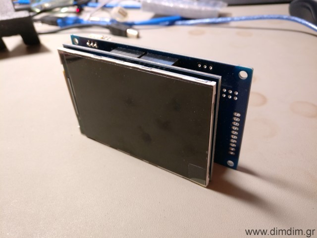 Hardware selection
The DAC needed to be controlled by a microcontroller so I looked into my options. I wanted something that would:
- Be easy to program, so the Arduino IDE was a must.
- Be able to drive a TFT.
- Have enough storage capacity to store enough code & fonts for the TFT.
- Be readily available.
- Be relatively low cost, since it would have no influence on the dac’s SQ.
- Be easy to build / integrate into a new design, even by a novice.
After some consideration, I decided to use an STM32F103 ready-made module. It would plug in to a “mainboard” of my design, along with the chosen TFT. It would be fast enough, have enough flash & ram, be easy to integrate and develop for and it would cost next to nothing.
Next up was the TFT. I’d seen on Ebay an interesting one that was relatively big, high resolution and inexpensive. It was this one:
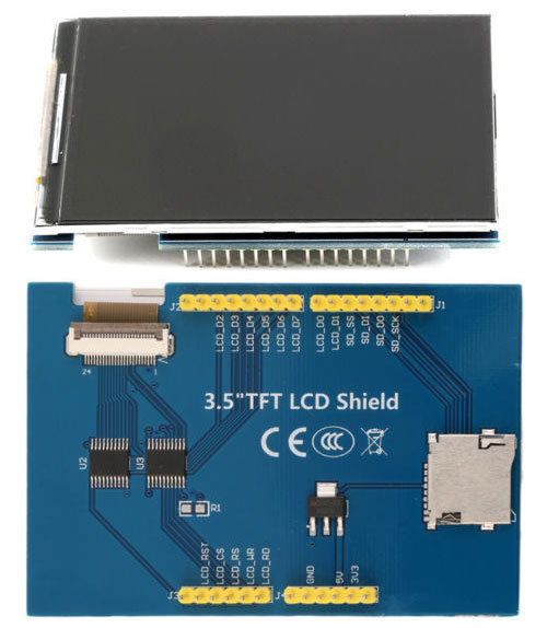 It can be found on Ebay by searching for “3.5 tft uno 320 x 480”. Expect to pay 6-8€ inc. shipping.
After some searching I found a suitable library that (after some slight tinkering) would allow my tiny STM32 to drive it properly. (Note: do not download the library from this link. I will provide a customized version of the library together with my code).
I found a ready-made library for configuring the Si570 and modified it to run on my STM32, using one of its hardware I2C ports. I will also include this library in my code. To complete the recipe I also found working rotary encoder and IR receiver libraries.
The code
Next up was the prototyping work. I adapted my TFT HiFiDuino Pro code to run on the STM32 & TFT combo, with support for AK4490 dual mono operation. The end result had this feature list:
- Support for either Dual Mono or single chip setups.
- Support for the Amanero Combo384 USB to I2S module (must be set up as slave with MCLK/2 and F0,1,2,3 enabled).
- Control with one rotary encoder with push-to-select functionality.
- IR Remote support.
- Support for software volume control, from -99dB to 0dB
- Display incoming signal sampling rate and type, determined by “reading” the relevant I/O pins of the USB to I2S board.
- Display and control of the AK4490’s digital filter.
- Selection of the proper MCLK frequency according to incoming SR and type and programming of the Si570 accordingly.
- Control of “DSD Direct” function of the AK4490s.
- Control of the DSD Filter’s Frequency (50KHz or 150KHz).
- Control of the Sound Mode of the AK4490.
- Choice of either inverted or normal analog output for the AK4490s.
- Choice of two sets of MCLK frequencies, either 22/24MHz or 45/49MHz.
- Remote power on/off functionality (or always on – configurable in the code).
Software Requirements:
- TFT Library (included in ZIP, derived from this one: http://stm32duino.com/viewtopic.php?f=9&t=1751). I have also available a modified library that will work with 3.5″ TFTs using the ILI9486 controller, such as the ones offered on Ebay lately. Download here: Adafruit ILI9486 8bit STM library (266373 downloads )
- Rotary Encoder library: https://github.com/mathertel/RotaryEncoder
- Adafruit MCP23008 library (included in ZIP, derived from this one: https://github.com/adafruit/Adafruit-MCP23008-library)
- Adafruit GFX library: https://github.com/adafruit/Adafruit-GFX-Library
- Si570 library (modified to utilize the STM32’s hardware I2C pins, included in ZIP, derived from this one: https://github.com/afarhan/radiono/tree/master/radiono)
- IR remote library, compatible with the SMT32 (modified version of this library, sourced from here, also included in the ZIP)
In the download I am including the modified versions of the libraries (as mentioned above) as well as the necessary font files. Be sure to extract the contents of “Libraries (place in Libraries folder)” to your Arduino IDE’s “libraries” folder.
Download it here: aKduino v2 (157791 downloads )
Here is the revision history:
v1.72 24/12/2017:
- Minor changes to make compatible with current stm32duino core (changed HardWire.h to Wire.h and other minor stuff).
- First public release as part of completed dual mono DAC project.
v1.66 10/10/2017:
- Minor volume bugfix.
- SuperSlow filter still problematic.
- Enabled DAC synchronization feature (experimental..).
v1.64 30/09/2017:
- Bugfixes.
v1.60 20/09/2017:
- Added support of rotary encoder and IR remote control.
- 3.5″ TFT support.
v1.50 07/01/2017:
- Added support of rotary encoder for volume control.
- Bugfixes related to DSD.
v1.41 06/01/2017:
- Added support for dual mono mode.
v1.36 03/01/2017:
- Added very basic TFT support.
v1.35 20/12/2016:
- Code cleanup for first public release.
v1.33 19/12/2016:
- Added full control of sound parameters through serial port.
v1.27 18/12/2016:
- First functional version.
- Automatic switching between PCM and DSD by monitoring DSDPIN.
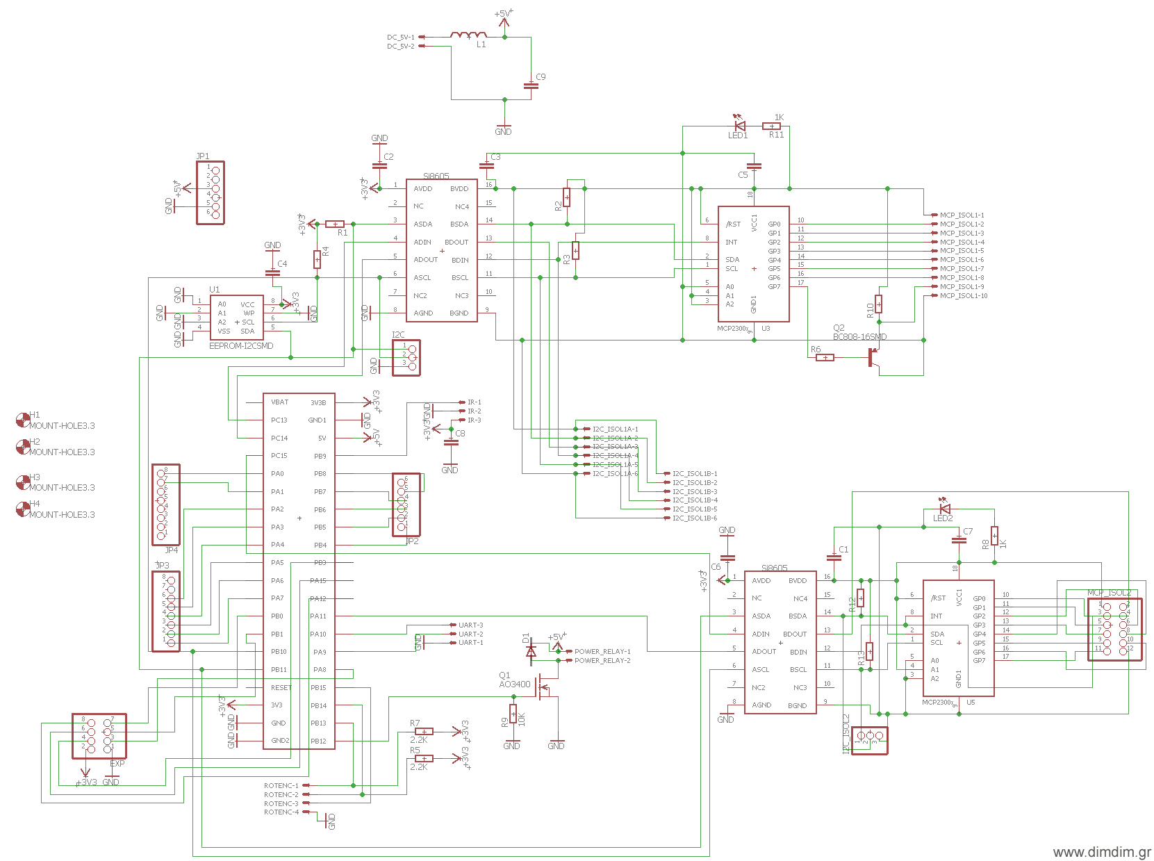
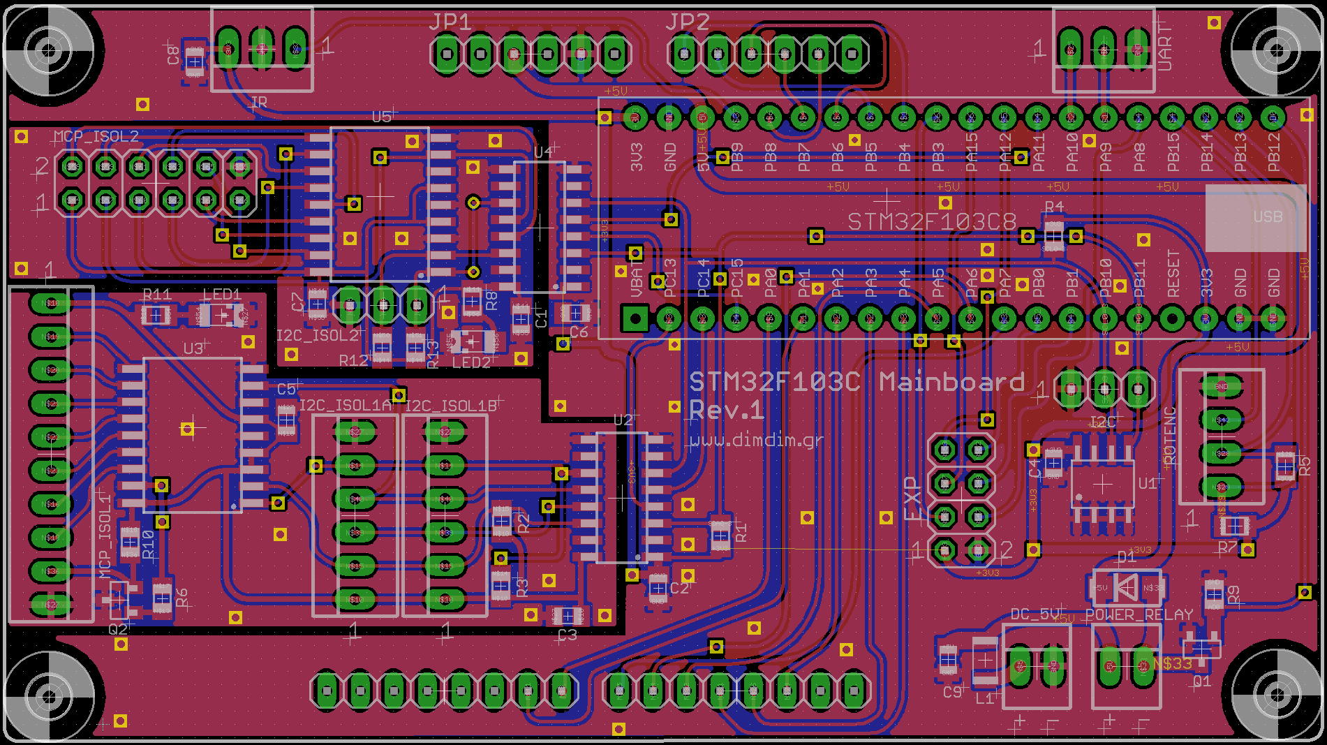
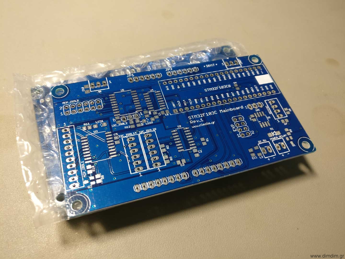
The “motherboard”
After I was certain that everything related to the software was working the way it should, I designed a “motherboard” that would take care of the following:
- Accept the STM32F106 board.
- Accept the 3.5″ TFT.
- Accommodate an 24LC256 EEPROM chip, used to store the DAC’s configurable settings.
- Accommodate two sets of I2C signal isolators and I/O expanders.
- Include headers for the encoder, IR receiver, power relay, non-isolated and isolated I2C communication, unused uC pins, etc.
This is what I ended up with:
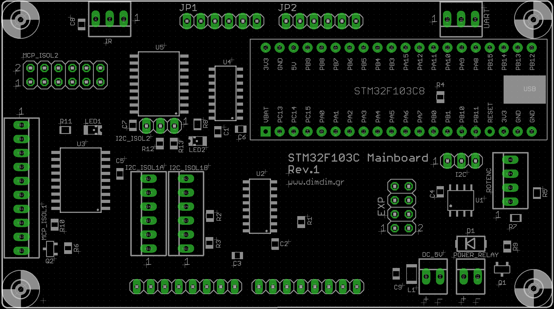
 Basic Hardware Requirements:
- STM32F106 module (a.k.a. “blue pill”, search Ebay for “stm32f106c8t6 board”)
- 3.5″ TFT with resolution of 320 x 480 (Search Ebay for “3.5 tft uno 320 x 480”)
- 24LC256 EEPROM chip
- I2C Isolator ICs, I/O expanders, passive components, etc (see BoM)
- Rotary Encoder
- IR Receiver
- Compatible IR remote control (Apple Remote or other – in any case you must edit the code and input the proper IR codes for your remote, see below)
How do I make it work?
Power
You have to supply the board with 5VDC at ~300mA through header DC_5V.
[table “” not found /]
Basic connectivity
Serial port:
[table “” not found /]
Rotary encoder:
[table “” not found /]
IR control:
[table “” not found /]
If you will be controlling a power on/off relay, you can use the POWER_RELAY header:
[table “” not found /]
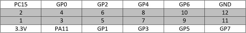
Expansion header:
[table “” not found /]
I2C header (non-isolated):
[table “” not found /]
Isolated I2C ports
The board has provisions for two separately isolated I2C ports, complete with I/O expanders on their isolated sides. The idea is to connect the DAC board to one of the isolated ports (I2C_ISOL1 & MCP_ISOL1) and your USB-to-I2S board to the other isolated port (usually MCP_ISOL2)
[table “” not found /]
[table “” not found /]
[table “” not found /]
 That’s it for Part 2. Stay tuned for Part 3: The output stage.
Great! Could you upload aKduino v1.41? I need only dual mono mode for AK4490.
v1.41 is pretty old.. There’s a good chance it’s buggy or not compatible with the current stm32duino core. I could email it to you (use the contact me link) but if I were you I’d just adapt the current version to my needs. Cutting out stuff is easy..
OK.
Hi Dimdim!
Why in the sketch:
// Remove comment slashes (“//”) from your USB interface. Keep all other interfaces commented out.
#define Amanero
// #define DIYINHK_XMOS
// #define JLSounds
// #define WaveIO
Because I was reusing some older code that included support for all 4 of the USB interfaces and I forgot to take these 3 lines out. 🙂
Library for the encoders RotaryEncoder.h is absent 🙁 .
It’s not supposed to be included in the ZIP file because it’s not modified by me. I only include the libraries that I’ve needed to “adapt” to this project’s needs. For libraries that can be used “as-is” I prefer to just link them.
Hi Dimdim,
Excellent project, thank you for sharing it!
I am working now to draw my own version of 2 layers PCBs, with Xmos XU208 (for I2S of course, but also for I2C commands), and your project is a great source of inspiration.
How did you managed the click noise between DSD tracks, only software mute or will you use relays?
Thank you in advance.
Thank you for your kind words. 🙂
I too am finishing up an XMOS design with the XUF208 as well as an AK4118 for s/pdif inputs, no I2C though. I have the uC for that.
The AKM dac chips have well documented problems with pops when changing between pcm and dsd.. they (akm) recommend using a relay to mute the output before making changes in the signal formats. But I don’t really remember having problems switching between different DSD tracks. I’ll check to see if it’s something I missed. The dac is still in development mode, so I’m not really listening to it most of the time.
I have made a few XU208 and XUF208 boards using Amanero PCB size and pinout. The main reason was that Amanero requires different firmware for Windows and Linux (Daphile) and I want to avoid this situation. I have been tested them with a Chinese DAC based on AK4490, but the relay is not fast enough and sometimes I can hear a pop/click for a fraction of time before the relay acts.
I finished a USB DAC project based on XMOS XHRA and dual AD1955 (controlled by a PIC uC) with I2S and SPI isolators, but the sound is better without isolators. Obviously it needs reclock and XMOS working as slave.
The PCB I am working now is intended to be configurable, so if I will not succeed to make XMOS working as real slave, I will replace it with Amanero module, I will add STM32Duino board and I will move a few jumpers.
Thank you and good luck!
Interesting that the relay turns out not being fast enough.. I have been worried that I would also have such a problem but I have not got there yet. Perhaps some solid state solution might be a better choice. I’ll look into it and keep you posted.
Regarding the XMOS in slave mode, do you mean “real” slave mode, as in the dac generating the BCLK & LRCK signals and feeding them to the XMOS (along with MCLK) so that it only generates the DATA line, or just slaving the XMOS to the dac’s MCLK?
Just slaving the XMOS to the DAC’s MCLK.
When I said “real” I was thinking about my last finished project. The clocks are located near the AD1955s, on the clean side, I2S isolator is 3in-1out version, so I force the XMOS to be a slave without programming the XMOS accordingly. As you know, XHRA is some kind of XU208, but factory limited to the “official” firmware. It was obviously from the beginning it will not sound well, but it was worth to try.
hey, thanks, great work 🙂 Took a look at the code and it seems to be really well understandable. I like that a lot!
Looking really forward to putting my dual ak4490 (china made board with XMOS U8) in this case: https://www.fein-hifi.de/images/product_images/original_images/256_0_rt935axb.jpg
Not sure if I really reuse the VFD display since these are, electrically, a real pain to drive (basically they’re display tubes) or just put a SSD1306 0.98″ OLED there; but either way the tuner looks really nice in my Rotel stack 🙂
By the way, what’s the code’s license? Public domain, GPL,…? I’m *considering* packing a lot of your AK4490/AK4118 stuff into separate libs to make it easier to reuse (and publish it on github under the same license, preferably GPL, and of course referencing you as the original author in each file).
btw, this post is missing the ak4490 tag, that’s probably why I missed it and asked for it on part 1.
Crap, I missed this comment! Sorry..
I haven’t really given much thought to a license for the code. AFAIK if I make no mention of a specific license it “defaults” to a very permissive license. So, for the time being, everyone is free to do whatever one wishes with my code. 🙂
You’re right about the tag, I’ve fixed it..
Haha, no problem 😉 and thanks 🙂 I’ll post the link here once I tested the lib (which might take some time since I’m doing a lot of stuff in parallel in my spare time and I’m moving in with my gf ^^’)
Would this also work on the ak4497 chip ?
I haven’t gone that deep into studying the 4497’s datasheet but I doubt it.. Many of the parts of the code will probably work, but the 4497 is not register-to-register compatible with the 4490.
The more i read your blog the more I am intrigued to build your dual mono dac. I am bit novice on diy dacs but have soldering skills.
How the dual dac compares (soundwise) to the single ak4997 diyinhk board?
I haven’t listened to any 4497 based DACs.
Pingback: Arduino controlled Dual Mono AK4490 DAC (Part 1) | Dimdim's Blog
Hi Dimdim,
Thx for Your work. I;ve bought tft board and i;m trying to get it works. I use stm32 and Yours librarry Adafruit_ILI9481_8bit_STM. I still got white screen. I;ve checked all wires, i;ve made a small test application to check if all pins of STM react for command on/off.
Arduino 1.85, Your librrary 1.72. The readID() return xD3D3D3D3 instead of 9481. Bellow is diagnostic print:
Display Power Mode: 0xA
MADCTL Mode: 0xB
Pixel Format: 0xC
Image Format: 0xD
Self Diagnostic: 0xF
Device ID: 0xD3D3D3D3
Any suggestion? Maybe it it’s bad TFT screen (out of order/dead).
Best rgds
Marek
It might be a bad LCD, but it also might be an LCD with a different controller. Does it look exactly like the one I have?
I have come across a couple of seemingly identical LCDs that worked but displayed an inverted image.
Pingback: Arduino controlled Dual Mono AK4490 DAC (Part 3) | Dimdim's Blog
Hello.
It is a very wonderful site.
By the way I want to control multi channel DAC (4 x ak 4490) without your si 570 with your controller. Is it possible?
It seems difficult for me to rewrite code.
please help me.
The AK4490 has a configurable I2C address that can be one of 4 unique values, so if you set up each one of your 4490s with its own unique address you can control all of them with a single I2C bus from a single controller. If you look in my code I mention the different possible 4490 addresses and how to configure the code for them, assuming I’m controlling 2 x 4490s each of them in mono operation. It wouldn’t be difficult to change the code to support 4 chips in stereo operation, all of the building blocks are there. But you will need to learn how the 4490 chips work by reading the datasheet and then make some changes to the code. I cannot do that for you, I simply don’t have the time. But I can help if you get stuck somewhere.
Thank you.
Yes, I saw the code. Is it possible to perform 8ch play and volume control just by setting CAD 0 & CAD 1 of the board?
The CAD pins only configure the I2C address of each chip. You then have to “talk” to each chip over I2C to control its volume and set it for stereo operation (not much to do for the latter – by default the 4490 will work in stereo mode).
Thank you for answering.
I will try erasing the code of SI 570.
I will also try to see if 4 filter settings are switched at the same time
Before you start changing things in my code you will need to read the datasheet so as to decide what exactly you would like to do, like running the 4490 in auto or manual mode. These decisions influence parts of my code.
I read the datasheet.
I want to set SR automatic setting and fix it to 24 bit, but even if I change the code register 0H to 10000111 it does not work. I am in trouble because I can not compile by merely deleting the Si 570 code.
Hi Dimdim,
should it work with a screen with ILI9486 driver? The ebay sellers are always sending a screen with ILI9486 driver, instead of 9481.
Hi there, I too have come across this problem so I made some changes to the Adafruit display library in order to support the ILI9486 driver. I’ve just edited the above post and added a link to the modified library.
Hi Dimdim,
I’m sorry for the late answer, but I waited a notification email. I clicked one of the notif opportunity (I don’t remember which one…probably I should have clicked the another one). I just read your answer Friday evening. Never mind….
So it works, thanks a lot for your post! Volume adjusting works with rotator (the panel is alone now without DAC), but it doesn’t work with IR remote. I use Apple remote (in alu case, I bought it 3 years ago). You wrote that your example IR code have to be changed to our type (code). I checked it in your IR Data library in apple.txt. Vol down code is 0x000d. So I modified from VOLDOWN_CODE 6 to VOLDOWN_CODE 0x000d. I doesn’t work. In Wikipedia the code is 0x06, I tried it. And I tried with 77E1B04D and it’s decimal form: 2011279437. Neither works. Am I completely wrong way? Could you give me some guide? Sorry for lama questions… Or if there is anybody who uses the same IR remote could he share the right code?
Another question: My final goal is to use this brilliant solution for AK4497. I have AK4490 as well, I will connect the panel to the 4490, hopefully tomorrow. Several months ago you mentioned you would probably try AK4497 DAC. Do you have any experience with AK4497? I know, there is a little difference between programig the two chips. I don’t want to invent the warm water if not necessary.
Thanks for your answer in advance!
Btibor
Hi there Btibor,
Regarding the Apple remote, the easiest way to get it working is to open the serial port and see what codes it outputs when you press the buttons on the remote. It should say something like “Unrecognized command xxxxxx”. Put these IR codes in the code and upload.
Regarding the AK4497, I still plan to do a design with it, but I have no definite time plan since I have literally no free time these days. What I can say for sure is that it will be a dual mono design with integrated controller, XMOS and s/pdif receivers.
I checked the serial monitor. I can read all of the information (volume, menu, etc) what you can adjust with the rotator, but there is no any sign on serial monitor when I use IR remote. The IR works, I checked it with scope on B9 pin (and I checked it with two different type of IR receivers).
I just had a look at my code, in case I did not remember things right. When the code does not recognize an IR code it will output “unexpected value: xxxxx”. If it fails to do so it means that it does not recognize the IR protocol. But if you are using an Apple remote it should recognize the protocol. This is strange behavior. Can you try connecting your IR receiver to some other pin of the controller and modifying the code to use that pin?
It works! I could find the pin setup in the irmpconfig.h file. C15 pin was configured originaly for IR remote, there must be B9. After changing it started to work.
Thanks a lot!
Pingback: Arduino controlled Dual Mono AK4490 DAC (part 3) -Use Arduino for Projects
Hello,
does this code work with an AK4493 as well,
or are there several changes needed ?
I read in another blog-post of you that you designed a dual AK4493 DAC as well (?) –> http://www.dimdim.gr/2019/08/allo-digione-s-pdif-hat/
so I wonder if you ever adopted this code to the AK4493 ?
Hi there Dirk,
I’ve been meaning to post about the dual AK993 board for some time now (along with many other things) but time has been extremely limited lately.
To answer your question, the AK4490 code is for the most part compatible with the AK4493. What it lacks is the support for auto PCM/DSD detection and for selecting the extra filter(s). But the AK4493 should start up with no issues.
I’ll try to find time to post about the new DAC board and updated code.
Hello Dimitris,
Would it be possible to get a “motherboard” PCB for the STM32F106 and TFT?
Thank you
Maxi