
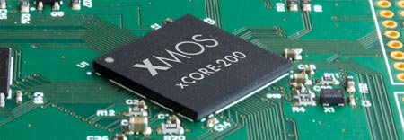
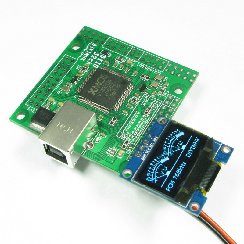
About a month ago DIYINHK released a USB to I2S interface board based on the brand new and all-powerful XMOS xCORE-200 chip.
![cXU216[1]](https://www.dimdim.gr/wp-content/uploads/2016/01/cXU2161.png)
The specific chip used by DIYINHK is the middle-of-the-line XU216-512 which corresponds to some pretty serious horsepower: 16 logical cores for a total of 2000 MIPS, 512KB SRAM, 2MB FLASH.
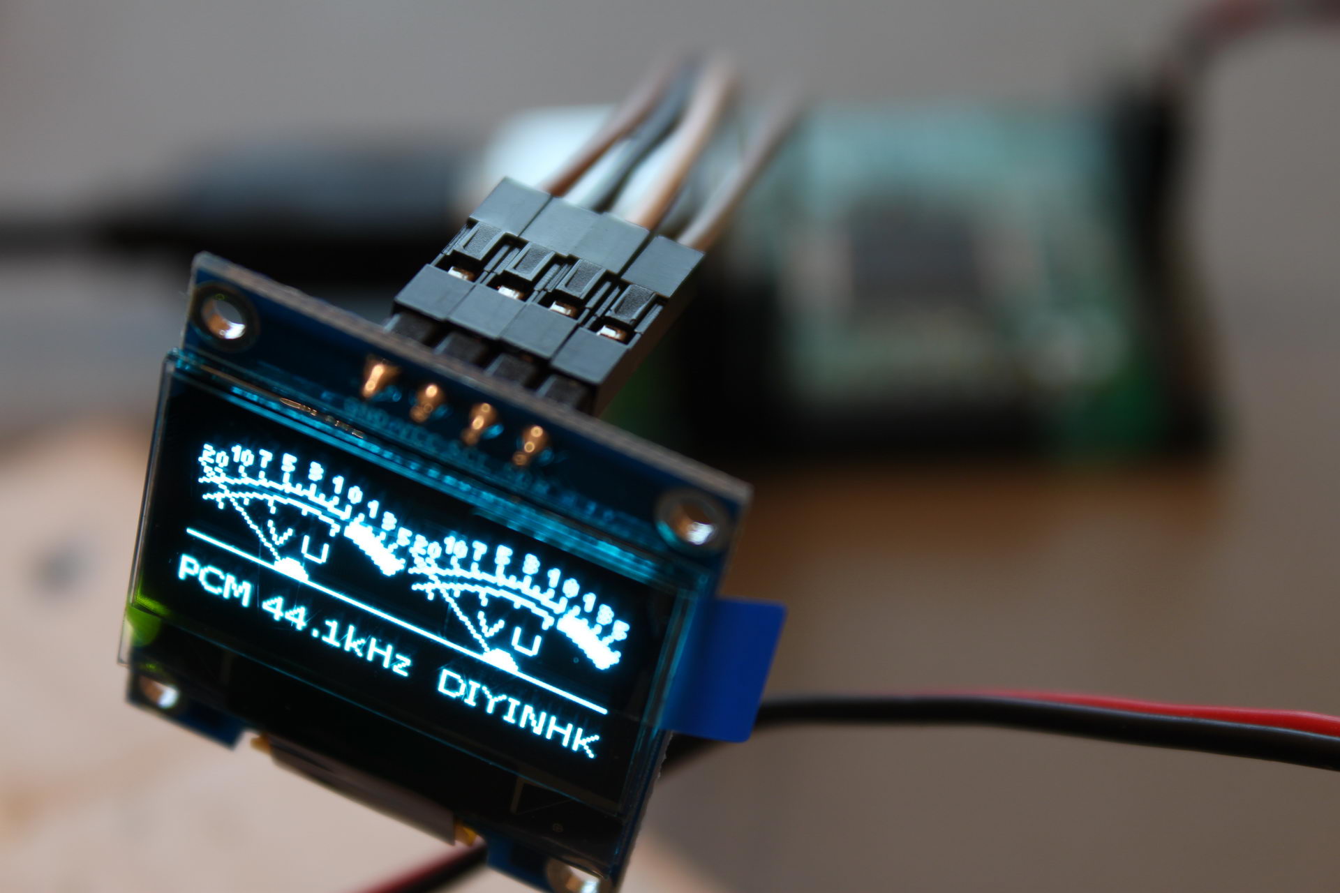
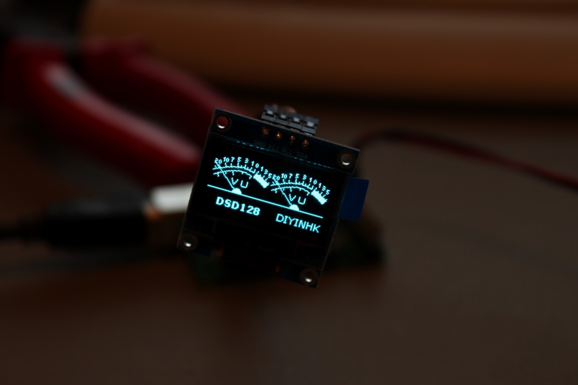
So, what can we do with all this horsepower you say? It’s simple. Tons of channels of high-resolution audio. Plus I2S inputs, besides the usual outputs. Plus DSD1024. Plus use a cool OLED display as a VU meter.
The board I bought came with the default firmware, which supports:
- 6 channel 384kHz I2S output
- 4 channel 384kHz I2S input
- spdif output
- OLED VU meter
- Volume up/down control button
Here is a video of it in action:
A maximum 32 channels can be supported with the right firmware (not provided by DIYINHK).
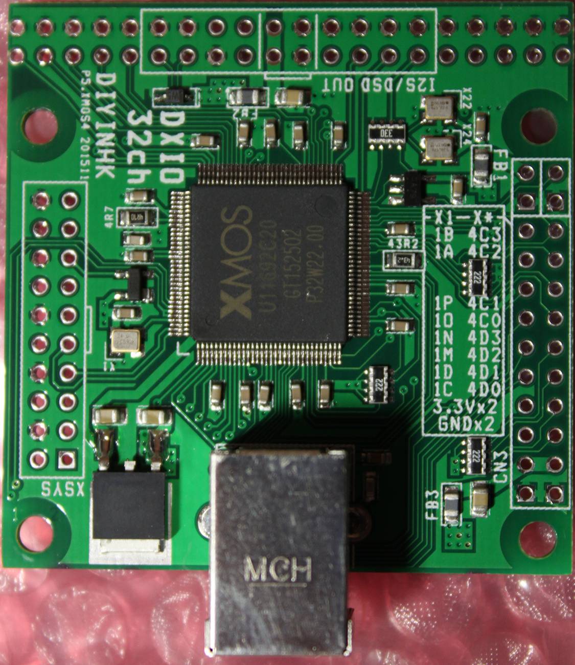
The board (a 4-layer design, btw) comes with three high quality NDK NZ2520SD Ultra low phase noise oscillators. There is provision for powering two of the oscillators externally, by removing a ferrite bead and applying power through one of the headers.
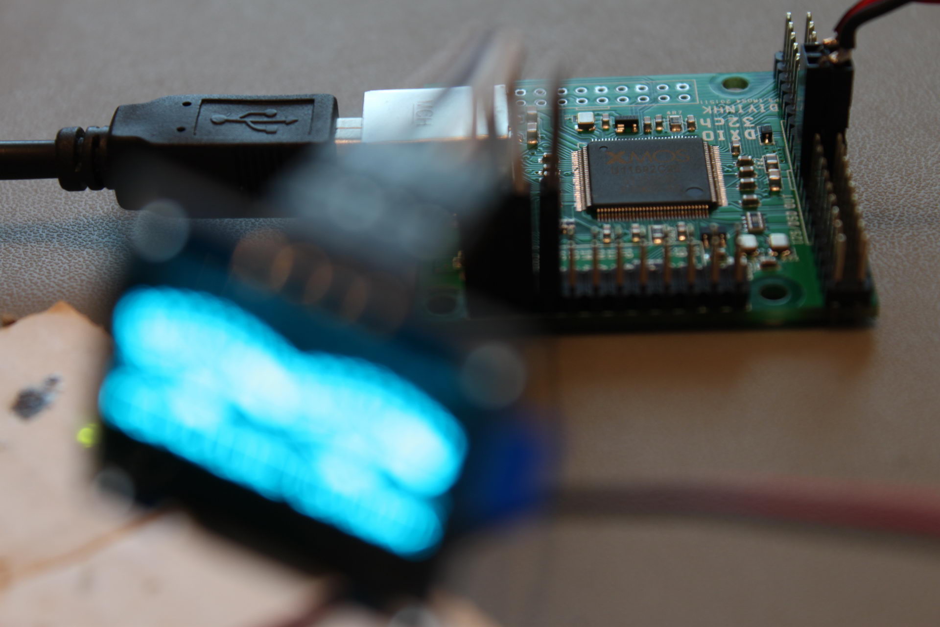
The board is not USB powered. It needs a relatively beefy 3.3V power supply, capable of providing a maximum of 800mA (even though a typical power consumption is in the neighborhood of 570mA). Beware, a weak power supply or an inadequate connector will cause to board to not power up.
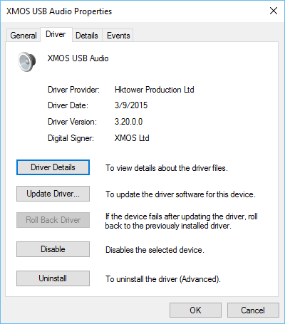
It comes with a fully featured Thesycon driver for Windows. Linux & Mac OS don’t need a driver.
An interesting detail is that the Windows 10 driver that is available only supports stereo operation and no multichannel (v2.26). If you want multichannel you’ll have to go back to Windows 7 (v1.67) (or perhaps Linux or Mac OS, it isn’t clear..).
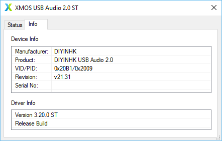
DIYINHK’s site says that the latest available driver is v2.26, but I did not find such a driver in their downloads section, so I emailed them about it. They sent me a link for an even newer driver, v3.20.
The board has a ton of exposed I/O, split into three 0.1″ headers. These are the pinouts, according to DIYINHK:
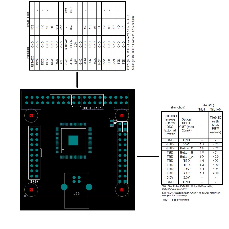
Now, if these pinouts look somewhat cryptic to you, you are not alone. I will try to clarify things a bit.
This is the most interesting header:
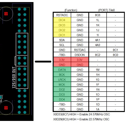
I have marked in red the power supply input. It is a good idea to use all of the pins for making the connections, since ~800mA is nothing to sneeze at.
The pins in green are the I2S outputs. For 2 channel operation you will need to connect the DATA, BCK & LRCK pins. The rest of the output channels should be available at pins DO2, DO3 and DO4. I say “should” because I haven’t tested them. I should repeat that multichannel operation with the provided driver is only possible at the moment with Windows 7 (and possibly Linux & Mac OS).
The pins in yellow are the I2S DATA inputs. For 2 channel operation you will need to connect the DIO1, BCK & LRCK pins. The rest of the input channels should be pins DIO2, DIO3 and DIO4. The same multichannel restrictions I mentioned above apply to the I2S inputs.
The OLED screen is connected to one of the side headers, like this:
The left header is the XSYS connector for uploading firmware to the XMOS.
Next up: connecting it to my PCM4222 EVM ADC board.
Have you compared the sonics of this USB rx to the other XMOS offerings and, if so, how do they compare?
No, not yet, but I will do some testing even though I don’t expect to find any significant differences, at least with the Soekris DAM1021 with its FIFO reclocker.
Im planning on using this wth the Soerkis DAC but im not clear about how to power them. so this board requires 3.3 v with 0.8 amps, how would u suggest to power it? i tried to find q diy kit linear poower supply for it but no luck. any suggestions?my second question is. how do you compare the capabilities of this diynhk board with this chinese one? http://www.shenzhenaudio.com/f-1-xmos-usb-digital-interface-board-xu208-chip-high-end-u8-upgraded-version.html
An easy way would be with an LM317 based regulator. Just be sure to supply it with a low enough DC voltage at its input so that it doesn’t throttle do to the large input to output voltage difference. A good choice of input voltage would be ~7VDC. But a Salas Reflektor-D would make for a much better power supply, just beware that you will be running it at its thermal limits, with a ~800mA CCS. A good solution would be the new Ref-D mini with its mosfets mounted to a bigger heat sink or the case’s bottom (if it’s big enough).
Regarding the F1, I’m not sure it’s a better sounding board. I can’t really theorize. I can see that it has galvanic isolation, a bad thing if you will be using it with the Soekris 1021 but good if you will use it with the 1121.
Thanks for your reply. i greatly appreciate it. On the Soekris website and on DIYaudio.com I only see 1021 … i am not even sure what 1121 is.
It’s this one: http://soekris.eu/shop/oem_line_dam1121_en/
OEM version, most likely better sounding but a bit more challenging build.
I see, looking at the picture, it does not have a power supply section onboard.
what is the difference between this XCORE200 board and this one? http://www.diyinhk.com/shop/audio-kits/107-xmos-dsd-dxd-768khz-high-quality-usb-to-i2sdsd-pcb.html
The one I have is multichannel, the other one is just stereo.
as far as using it to supply I2S signal from a PC goes is there any preference which one to use? i thought the things that you have done with Arduino are really cool and I want to use it. would it not be possibe with the stereo version?
For use with a DAC I would probably go with the stereo edition (blue board). Regarding the Arduino stuff, it doesn’t really make a difference. The Arduino doesn’t care which USB to I2S interface is used.
This is the power supply that DIYiNHK sells: http://www.diyinhk.com/shop/audio-kits/70-classic-reference-78xx-power-supply-linear-regulator-33v-5v-12v.html#/78xx_option-33v5v
will it do to use with the XMOS usb to I2S blard (the blue bloard)? the things that you said about the power supply mostly went over my head. i searched the Silas reflector and it only found a group buy from 2014 🙁
This power supply will not be enough – it can only do up to 500mA at 3.3V. Look for one based on the LM317. The Salas Reflektor-D has become a classic high performance shunt power supply but it is a bit more challenging to build (and pretty expensive compared to an LM317 reg). The group buy that you found is probably still going, if you feel up to it.
ok I see. thanks again. the current required for this usb board is ridiculously high. Im gonna buy the Reflektor but even that is rated at 0.6A.
Hi Dimdim,
Great info! I bought one of these together with a 8ch DSD capable dac. I am trying to get 8ch of DSD out, but the firmware is limited to 2ch. Have you experimented with custom firmware?
Best regards,
Paal
No, I haven’t done any serious experimenting with it mainly because I don’t have the necessary programmer. Plus I hear that it is not particularly easy to build a new firmware..
Did you try the latest version of the drivers? They are up to 3.38 right now.
Yes, I tried the latest drivers, but no multichannel support. I asked Diyinhk, but they tell me to mod the firmware for enable DSD multichannel. I have not studied a lot, but it seems to be more than one way to upload the firmware. The 1,67 driver also has a tab for firmware upload…
There ia also some info here: http://www.xcore.com/forum/viewtopic.php?f=47&t=4458&start=0
best,
Paal
hello DimDim
Can I have your help in a matter of connecting a DIYINHK multichannel board?
I’m attempting to hook an Alientek D8 digital amplifier to this board via i2s and
it hasn’t worked ‘out of the box’ …
I thought there was good reason to believe the connection would be straightforward:
the D8’s USB input connects directly to an XMOS based daughter board and removing the board revealed labels next to the pins!
I got a power supply with the DIYINHK board and soldered both in my amateurish way and
they seem to work: 8 channels (4 stereos) are accessible through a
suitable /etc/asound.conf configuration on a RPi3, and the VU meter shows a PCM signal getting through.
so that end looks ok.
and the D8 player itself plays (with the Xmos daughter board in place).
so, removing the daughter board and linking the DIYINHK board to the D8 with 10cm patch leads, I have (showing the printed pcb labels):
DATA >> SDIN
BCK >> SCLK (B for bit-clock?)
LRCK >> LRCK
I also tried linking GND’s directly.
then I tried linking MCK >> MCLK …. I guessed that the daughter board was feeding the main board pcb with a high frequency clock and that the DIYINHK should substitute for that.
but I do not know, in fact, whether MCLK is an input or output.
there is one more pin to the daughter board that I have not identified: SPD.
so nothing working for now. I do not have an oscilloscope. is there an oscilloscope android app that I could, at least, make simple ‘signal present’ checks with ?!
apart from suspecting my dodgy soldering the only other thing I can think of is a master/slave mismatch on the i2s. My only reason for thinking this not so likely is that both
the daughter board formerly in the D8 and the DIYINHK board are XMOS so perhaps configured the same way.
can you suggest anything to try?
cheers,
kris
Hi there kris,
Your wiring looks OK so the first thing I would check would be the frequencies of the original XMOS’ oscillators. If they’re different than the DIYINHK’s oscillators, you have a problem. Considering that the original XMOS board had on-board oscillators I would assume that it is providing the MCLK to the DAC board.
I’m afraid that most of these signals are too high to be detected by any PC’s sound card, much less by a smartphone’s mic. There is no substitute for an oscilloscope in this case.
thanks for the feedback. I’ve asked on diyaudio for anyone to measure their D8. If nothing comes of that I may buy a usb oscilloscope with android interface. but I live in hope I shall not have to!
meanwhile, I have the driver source and am on the verge of setting up the dev environment.
do you know whether the Xcore Xmos must operate with only particular clock frequencies?
if, as you suggest, the frequencies are different, is it likely the DIYINHK Xmos could have its master clocks factored up/down via software?
thought I’d ask before plunging into a dedicated xmos forum!
cheers.
I have almost zero experience with the XMOS environment, but I’ve read-up a bit on their USB Audio 2.0 library and it seems that you can factor down your master clocks via software, so using 44MHz instead of 22MHz (or the opposite) should be OK.
thanks for that. read it.
however, I think it unlikely the clocks are other than 24/22.
there was one pin labelled SPD which I couldn’t identify.
could you hazard an educated guess as to it’s function?
Dimdim, and what about this PS kit, is sufficient and good enough for this USB board? http://www.diyinhk.com/shop/audio-kits/59-10uv-ultralow-noise-dac-power-supply-regulator-33v-50v-800ma.html
Doubtful. While specc’ed at 800mA, the ADM7150ARDZ can only achieve that when its input-to-output voltage (dropout voltage) is very low, i.e. under 1V. Otherwise, it will throttle due to thermal constraints.
So, if you can manage to feed the board with precisely the right AC voltage necessary for outputting 3.3V with less that 1V dropout, you may be in luck. But that would mean a custom transformer outputting ~4V, so it would probably be easier to just choose some other power supply.
It seems not so easy to find some ready made solution for this USB board… What about some SMPS? Inspite of audiophile “traditions”.
An SMPS should work, but you could also use half of this one: http://www.diyinhk.com/shop/audio-kits/89-08uv-ultralow-noise-dac-power-supply-regulator-3357v-15ax2.html
Thanks for advise. Just will have to add fan/radiator.
And if I use half of that PS for XMOS, can another half be used to supply 3.3V 200mA for DIYINHK es9016 dac board? Any constrains for that?
I don’t see a problem doing that, as long as you are using a transformer with two separate secondary windings.
DIYINHK replied regarding PS for this XMOS board: “”””the latest version of xmos pcb uses less than 500mA, “””
Oh, that probably has to do with the newer batches using switching power supplies for the core of the XMOS. In that case you might be ok with the first diyinhk PS that you linked. The guys at diyinhk can definitely clarify that.
“”””The board (a 4-layer design, btw) comes with three high quality NDK NZ2520SD Ultra low phase noise oscillators. There is provision for powering two of the oscillators externally, by removing a ferrite bead and applying power through one of the headers.””””
What V and mA they would need each? The same 3.3 (800vA) ? Did you try this option?
Hi Dimdim,
I have the following USB -> I2S interface from DIYINHK: https://www.diyinhk.com/shop/audio-kits/113-xmos-384khz-dxd-dsd256-high-quality-usb-to-i2sdsdspdif-pcb.html
Wanted to use it with Soekris dam1021 and I have few questions:
1) gonna use LM317 based regulator to feed USB to I2S PCB, is it OK if I use 5VDC or lower/higher is preferable? Is it true that I should expect 800mA current?
2) Should I use same +3.3V pins from USB to I2S board to connect to DAC ISO +3.3V Pin (J3, 13) ?
Thanks in advance 🙂
Hi there Simon,
1) This USB interface has an on-board switching regulator that powers the XMOS’ core, so its power requirements are not significant. I believe that the stated 200mA should indeed be enough. But the voltage will need to be 3.3V.
2) You could but it has been reported that the power supply to the ISO_3.3V is critical regarding sound quality, so you may want to use something better there.
Thank you Dimdim,
Regarding second question, I was planning to use Salas UBiB to power the DAC via J1 with 12VDC. I was assuming that it was critical to have proper PSU on J1. Are you suggesting that ISO_3.3V is more important? Any better suggestions for PSU other than LM317?
Simon
I wouldn’t say that the ISO_3.3 is more important that J1, but it is important. I would go with an LT3042 based regulator for the ISO_3.3.
I wouldn’t say that the ISO_3.3 is more important that J1, but it is important. I would go with an LT3042 based regulator for the ISO_3.3.
I happen to have several spare UBiB 1.3 positive boards laying around. Any way I could mod it for ISO_3.3 ?
According to Salas there is a way but there are possible caveats: “If you want to try the possibility of shorting one LED, replacing M2 with a Logic Level MOSFET like the MTP3055VL along with changing R9 to 2.2k, it may work well enough down to 3.1V limit or not but I did not originally intend it or check it in that way. There will be no negative mirror lower voltage version if made so.” https://www.diyaudio.com/forums/power-supplies/322411-salas-sslv1-3-ultrabib-shunt-regulator-64.html#post5565576
I will give it a try, thanks !
I am trying to extract 8ch i2s signal from HDMI.
I have already took 8ch i2s lines out from a basic mch DAC but my minidsp usb streamer proved to be worthless for this project as it will not accept external master clock.
Just to make sure that we are talking about the same board https://www.diyinhk.com/shop/audio-kits/101-xmos-multichannel-high-quality-usb-tofrom-i2sdsd-spdif-pcb.html
I also see that a multichannel driver is also available at small cost.
Is this board able to accept external master clock?
Thanks Dim
I’m planing to use this xmos multichannel board from diynhk but I’m not sure how to connect 6 dac boards using i2s. Is that possible? Do you see any problem? What kind of dac can be connected regarding master and slave?