This post serves mainly as a placeholder for the build guide that I wrote for the PCBs, since it seems that some people had problems with the download link that I provided.
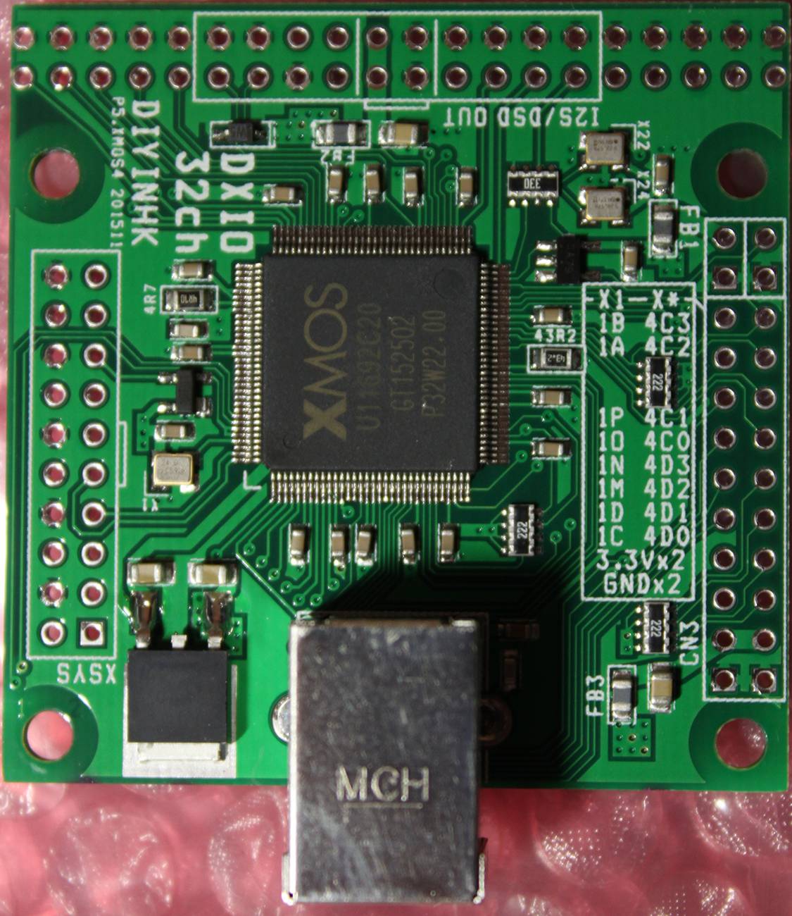
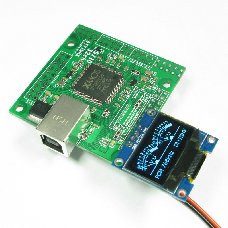
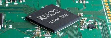
The specific chip used by DIYINHK is the middle-of-the-line XU216-512 which corresponds to some pretty serious horsepower: 16 logical cores for a total of 2000 MIPS, 512KB SRAM, 2MB FLASH.
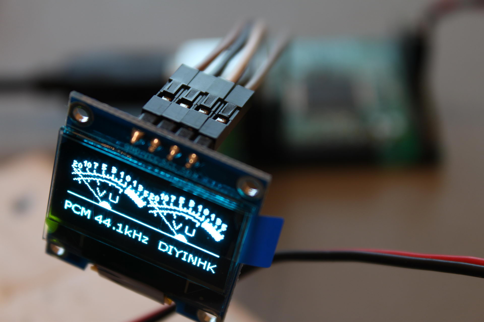
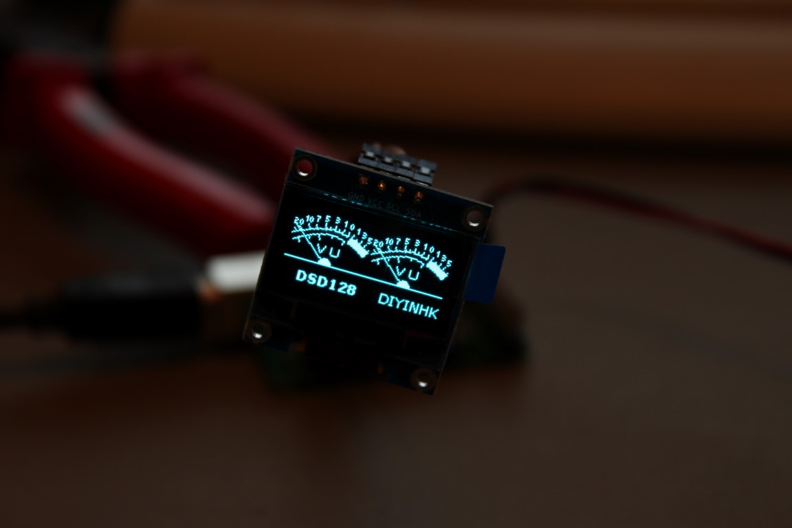
So, what can we do with all this horsepower you say? It’s simple. Tons of channels of high-resolution audio. Plus I2S inputs, besides the usual outputs. Plus DSD1024. Plus use a cool OLED display as a VU meter.
The board I bought came with the default firmware, which supports:
6 channel 384kHz I2S output
4 channel 384kHz I2S input
spdif output
OLED VU meter
Volume up/down control button
Here is a video of it in action:
A maximum 32 channels can be supported with the right firmware (not provided by DIYINHK).
The board (a 4-layer design, btw) comes with three high quality NDK NZ2520SD Ultra low phase noise oscillators. There is provision for powering two of the oscillators externally, by removing a ferrite bead and applying power through one of the headers.
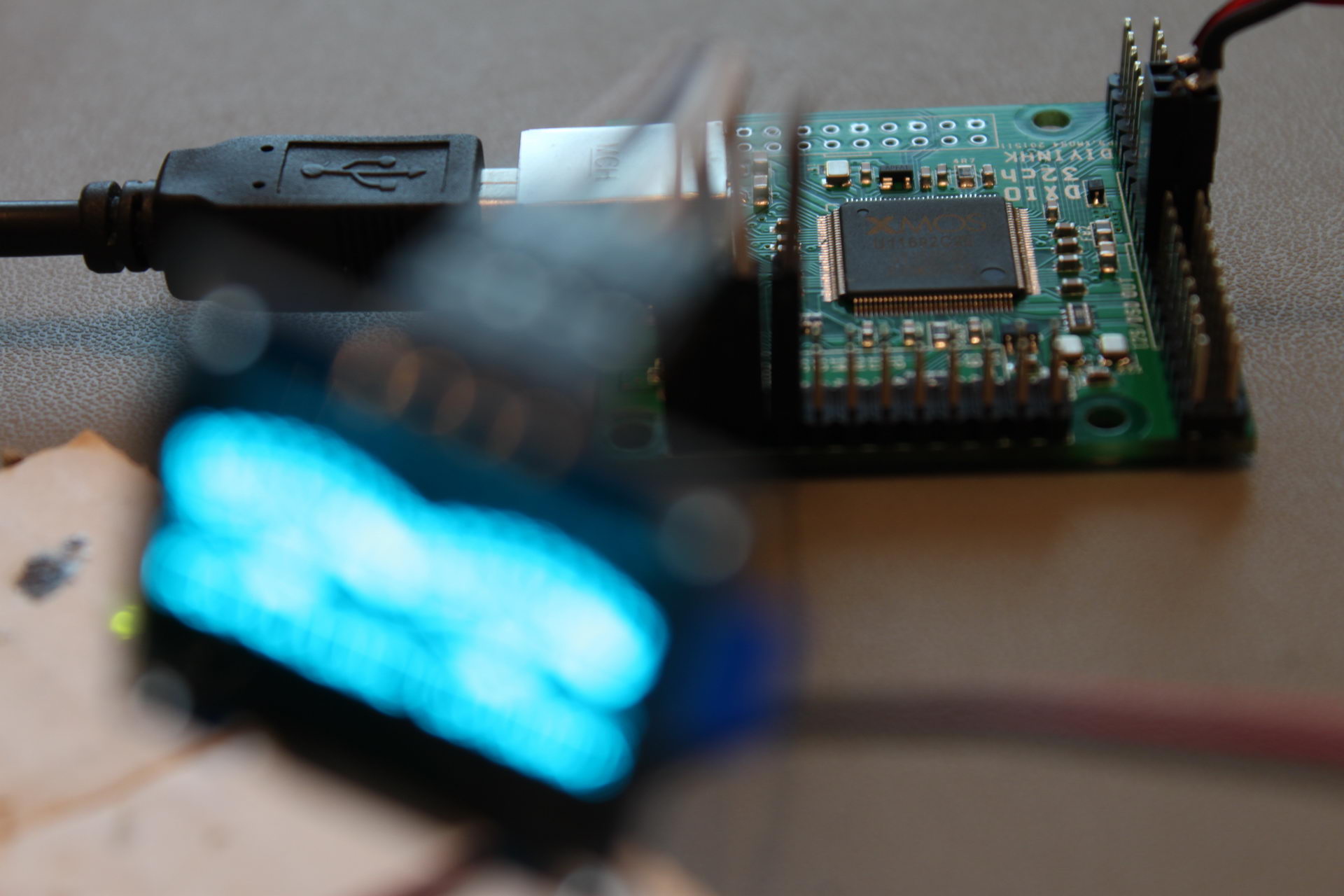
The board is not USB powered. It needs a relatively beefy 3.3V power supply, capable of providing a maximum of 800mA (even though a typical power consumption is in the neighborhood of 570mA). Beware, a weak power supply or an inadequate connector will cause to board to not power up.
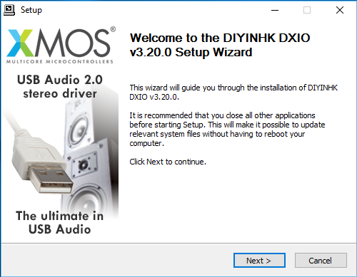
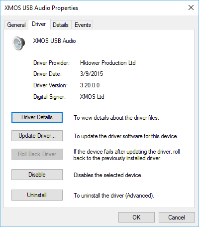
It comes with a fully featured Thesycon driver for Windows. Linux & Mac OS don’t need a driver.
An interesting detail is that the Windows 10 driver that is available only supports stereo operation and no multichannel (v2.26). If you want multichannel you’ll have to go back to Windows 7 (v1.67) (or perhaps Linux or Mac OS, it isn’t clear..).
DIYINHK’s site says that the latest available driver is v2.26, but I did not find such a driver in their downloads section, so I emailed them about it. They sent me a link for an even newer driver, v3.20.
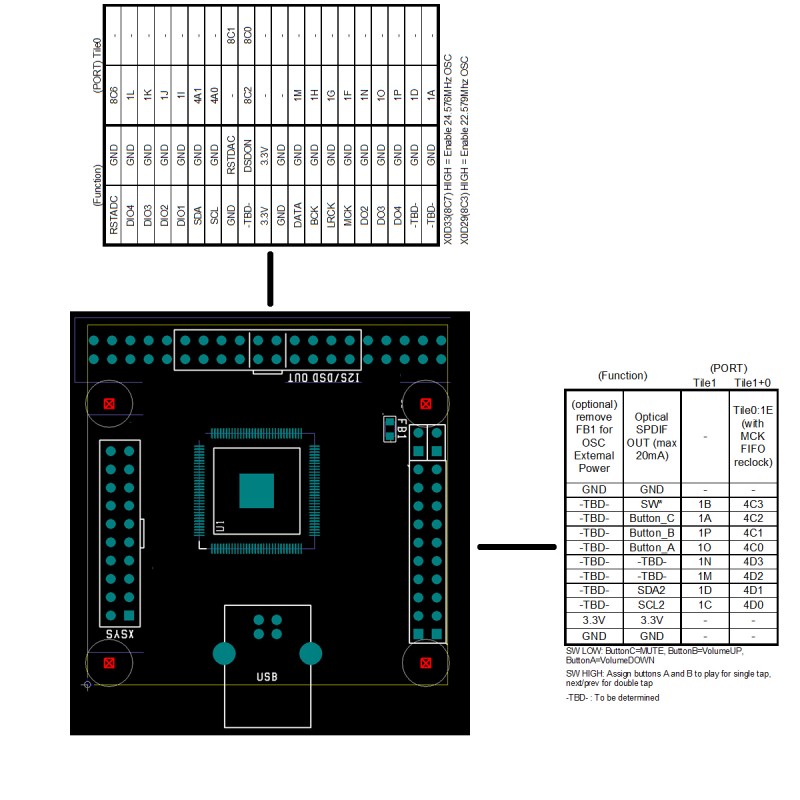
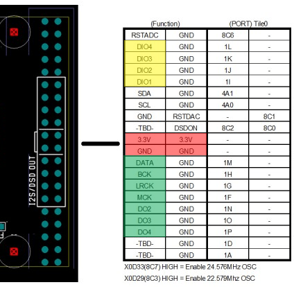
The board has a ton of exposed I/O, split into three 0.1″ headers. These are the pinouts, according to DIYINHK:
Now, if these pinouts look somewhat cryptic to you, you are not alone. I will try to clarify things a bit.
This is the most interesting header:
I have marked in red the power supply input. It is a good idea to use all of the pins for making the connections, since ~800mA is nothing to sneeze at.
The pins in green are the I2S outputs. For 2 channel operation you will need to connect the DATA, BCK & LRCK pins. The rest of the output channels should be available at pins DO2, DO3 and DO4. I say “should” because I haven’t tested them. I should repeat that multichannel operation with the provided driver is only possible at the moment with Windows 7 (and possibly Linux & Mac OS).
The pins in yellow are the I2S DATA inputs. For 2 channel operation you will need to connect the DIO1, BCK & LRCK pins. The rest of the input channels should be pins DIO2, DIO3 and DIO4. The same multichannel restrictions I mentioned above apply to the I2S inputs.
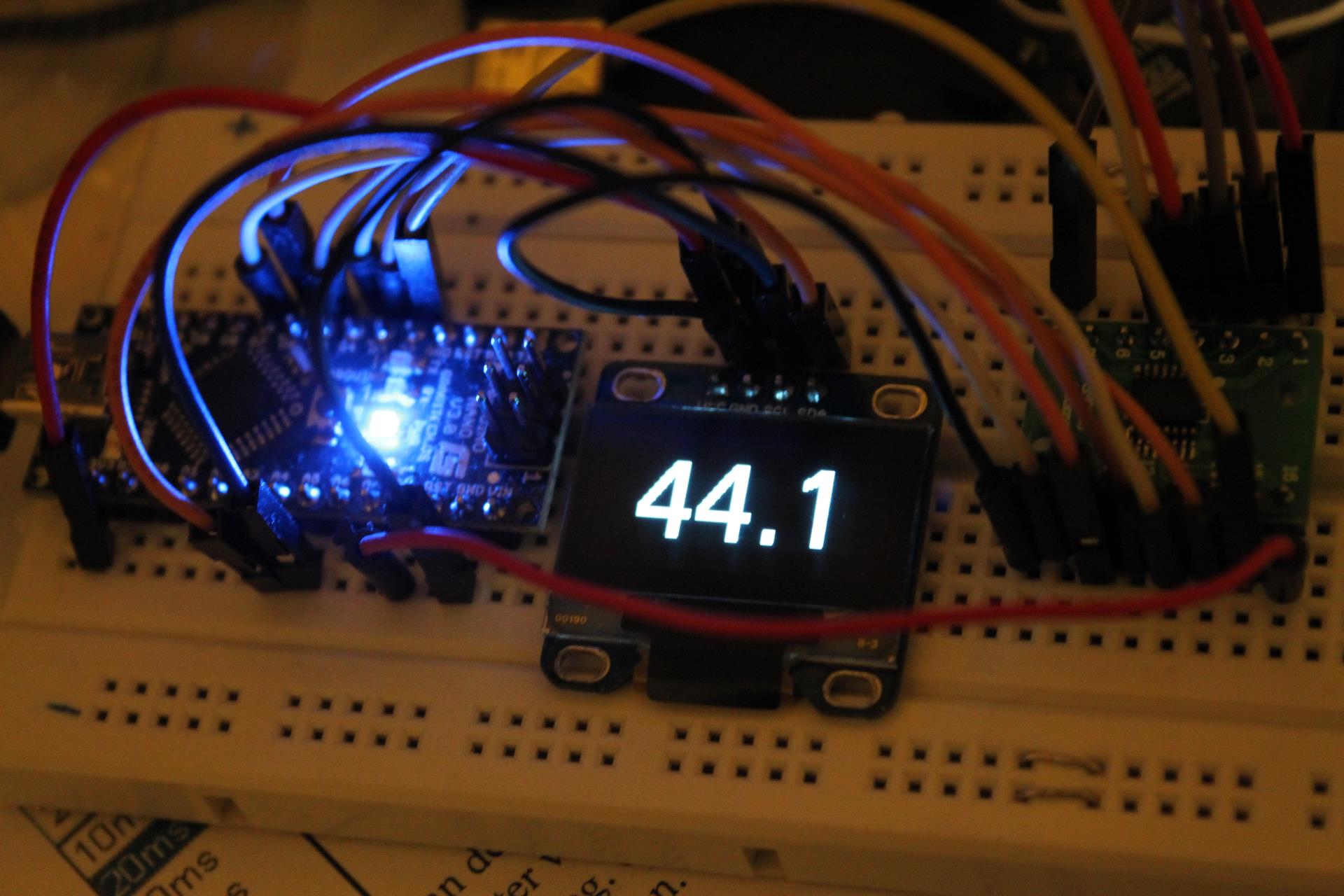
The OLED screen is connected to one of the side headers, like this:
The left header is the XSYS connector for uploading firmware to the XMOS.
Over at avclub.gr we designed a custom PCB to ease the implementation of the Universal USB to I2S Interface Indicator. It was a joint effort between myself and Manolis (a.k.a. lemon at avclub.gr). I did the circuit design and Manolis did the PCB design work.
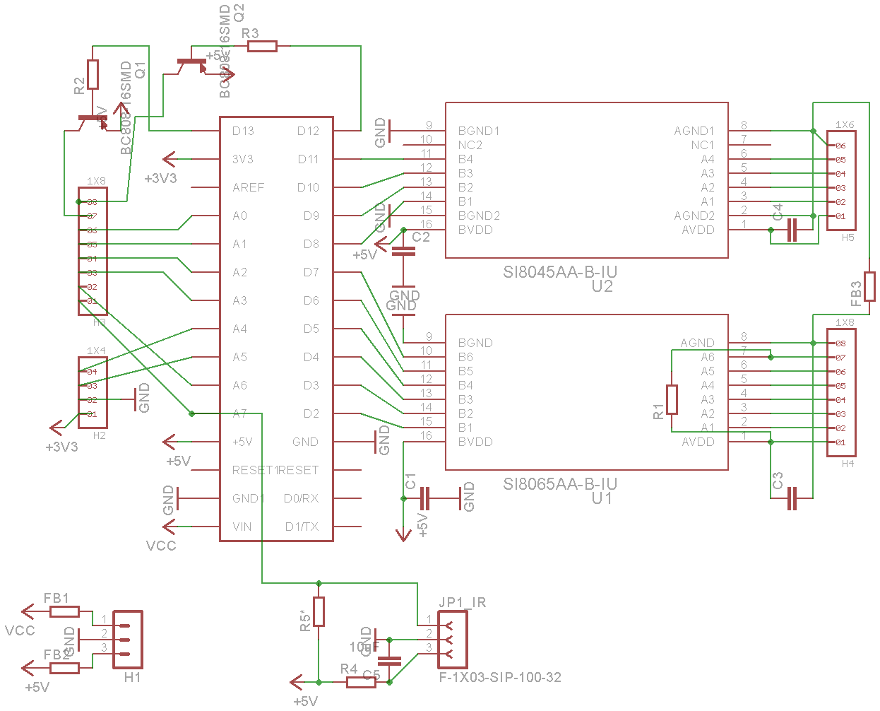
This is the schematic of the final version of the circuit:
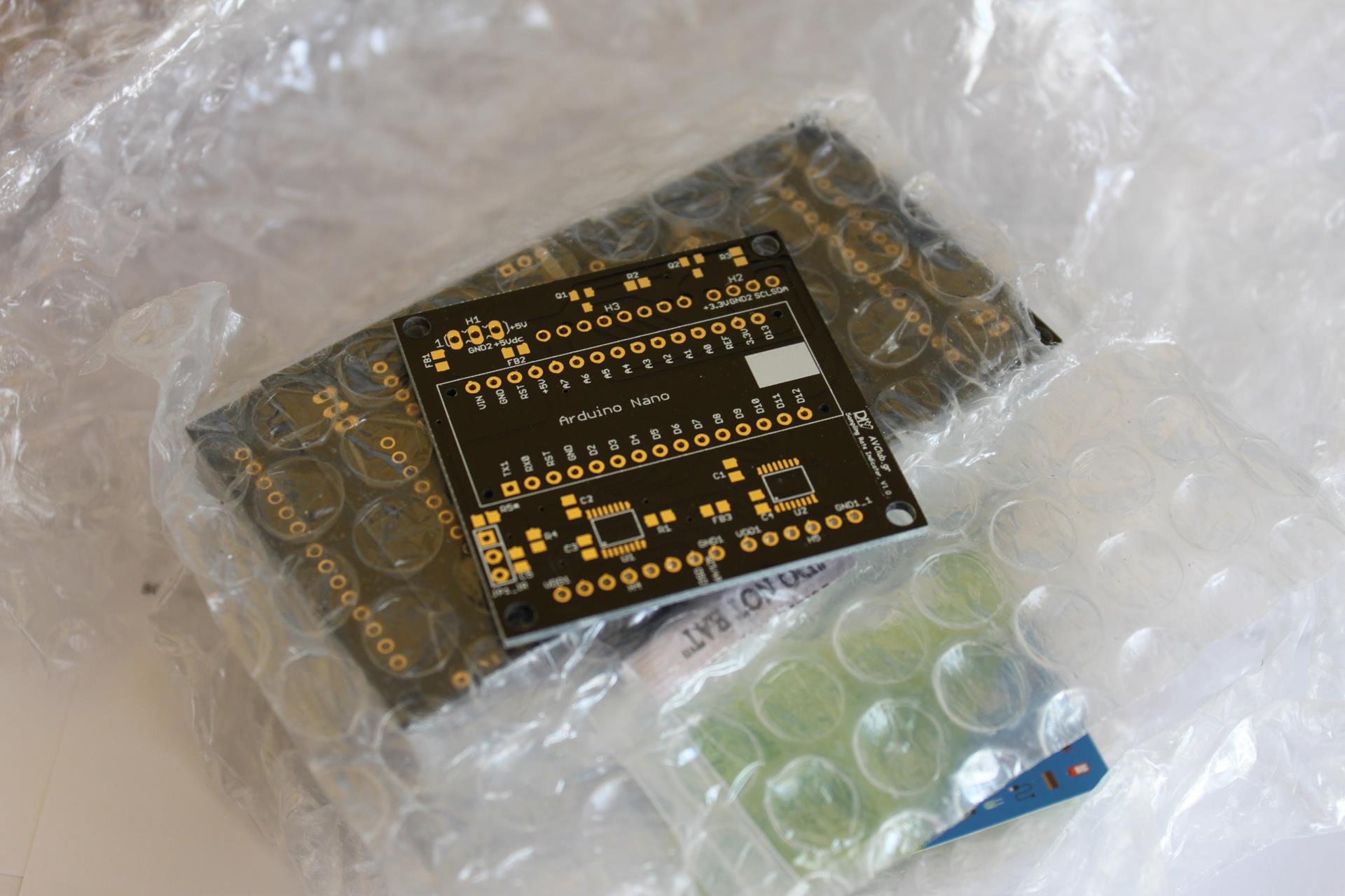
When the PCB design was finalized, a GB was organized. When the GB was finished we placed an order on seeedstudio.com’s Fusion PCB service. About 3 weeks later the PCBs had arrived:
The production quality was truly excellent.
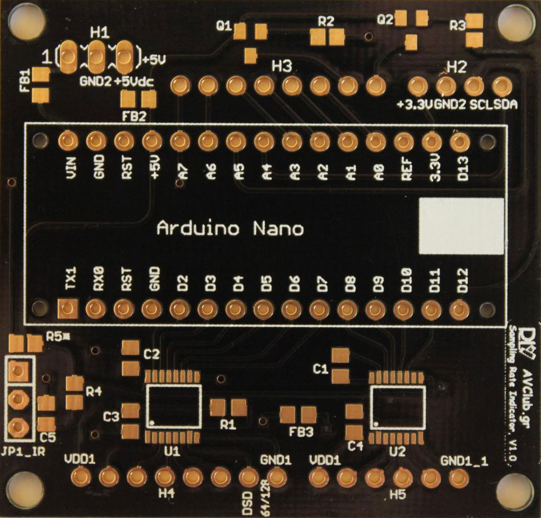
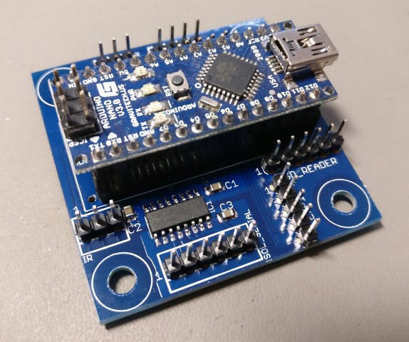
From top to bottom we have:
H1: Header for power. It may be either 5VDC (regulated) or 7-12VDC (non-regulated). Pin 1 is 7-12VDC, Pin 2 is GND, Pin 3 is 5VDC.
H2: OLED display connector. Pin 1 is 3.3V to the display, Pin 2 is GND, Pin 3 is SCL, Pin 4 is SDA.
H3: Header for future expansion. It exposes the unused I/O of the Nano in case it may be of use in the future. The last two pins are buffered by transistors so that they can supply enough current to engage small relays (5VDC, up to 100mA per pin). Pin A7 is connected to JP1_IR as well (see below).
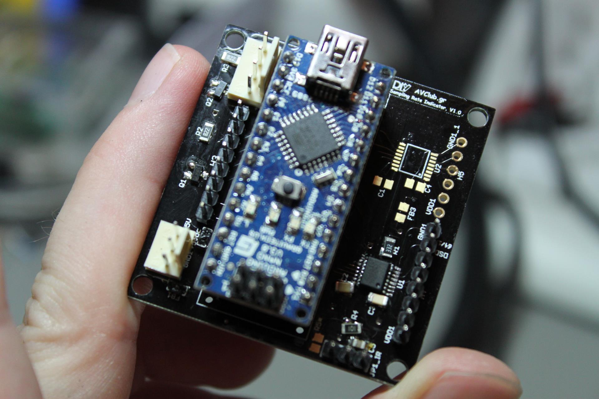
Next up is the socket for the Arduino Nano. You will notice that the USB port should be on the right.
At the bottom of the board we have:
JP1_IR: This is a connector for an IR Receiver module. Software support for this is currently in beta. Pin 1 is signal out, Pin 2 is GND, Pin 3 is power (5V). Note that R4 and C5 provide filtering for the power and should be installed. R5 is an optional pull-up resistor. It should not be installed for normal use.
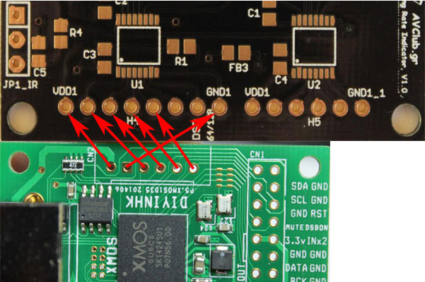
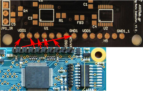
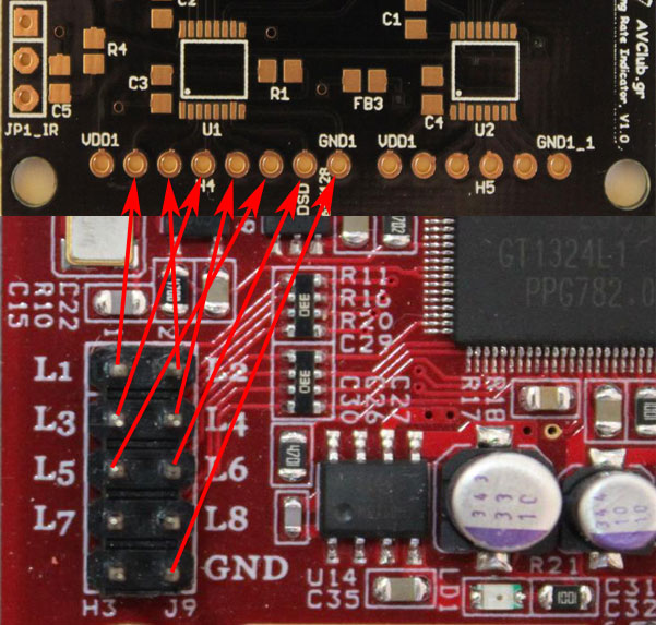
H4: This is the “dirty” side of the U1 isolator. Pin 1 is Vdd (usually 3.3V or whatever your USB Interface module uses for its logic levels). Pins 2 through 7 are inputs and Pin 8 is GND.
H5: This is the “dirty” side of the U2 isolator. Pin 1 is Vdd (usually 3.3V or whatever your USB Interface module uses for its logic levels). Pins 2 through 5 are inputs and Pin 8 is GND.
Note that in the future a Si8642BA may be used in place of U2. With proper support from the code that will turn 2 of the 4 inputs into outputs, so that they may be used to control a DAC board (for example to select an input).
You will also need an Arduino Nano, a suitable OLED display and some cables, connectors, etc. (see project page).
As soon as I received the boards, I built a prototype with whatever components I had lying around (thus the wrong size of most of the resistors & capacitors).
And proceeded to test it out with an Amanero Combo384 board:
Everything worked as it was expected. 🙂
At the moment this board (and relevant Arduino code) has been tested with the following USB to I2S interfaces:
Amanero Combo384 Note that R1 should be installed for proper operation.
DIYINHK XMOS
JLSounds I2SoverUSB
Luckit WaveIO
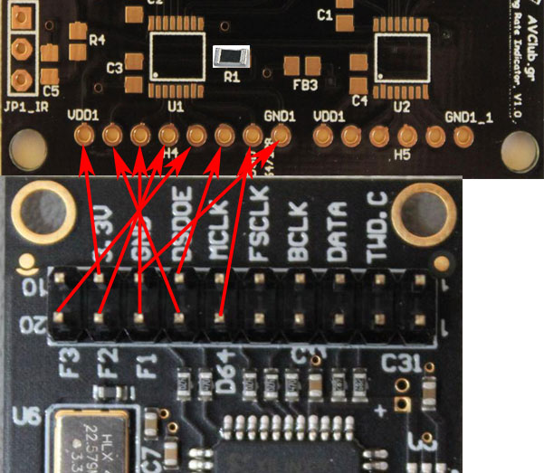
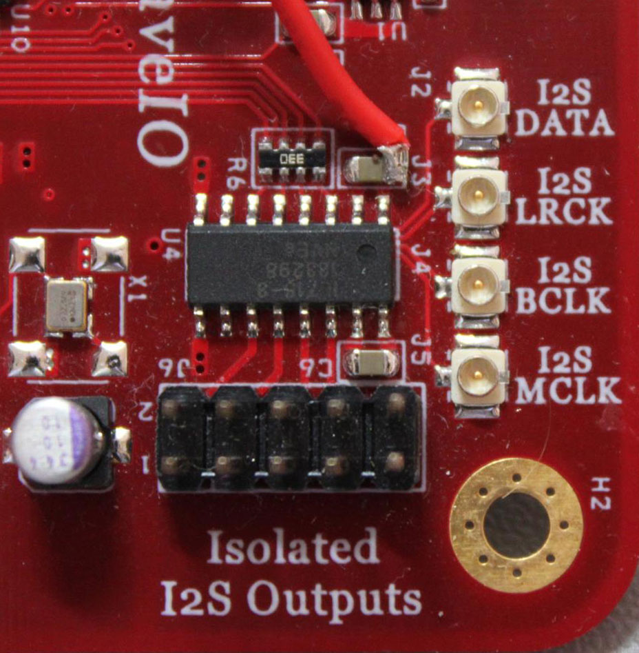
You will notice that there is no Vcc pin on J9. In order to power the isolator, we will have to “steal” power from elsewhere on the board. A good place to tap is the power pin of the on-board I2S isolator, just to the left of the I2S LRCK U.FL:
Following up on a number of feature requests made over at avclub.gr I made a few rather interesting additions to the code:
1) The OLED display will show the type of signal (PCM or DSD) for 3 seconds if a change in signal type occurs. Only supported on USB interfaces that support it (obviously).
2) IR remote control support via the well-known IRremote Library. Support for power on/off and source selection (S/PDIF or USB).
3) The OLED display will display the name of the selected source, permanently if it is S/PDIF or for 3 seconds if it is USB.
More details on the new features will be added to the project’s home page, as will the new version of the code.

![cXU216[1]](https://www.dimdim.gr/wp-content/uploads/2016/01/cXU2161.png)