
Following-up on my previous post, I soldered a Crystek 100MHz clock and had a new set of Trident replacement boards made for my upgraded Buffalo III.
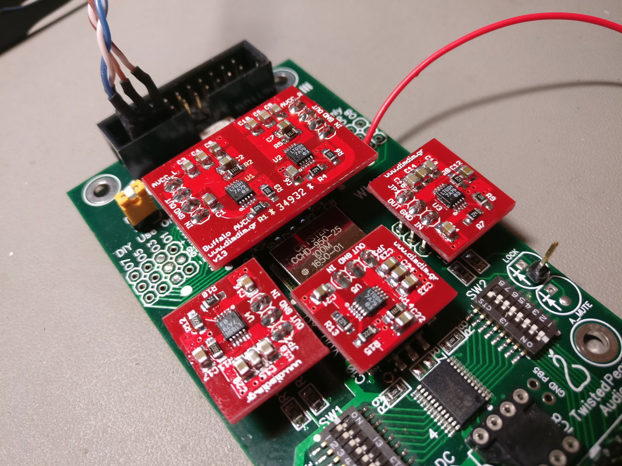
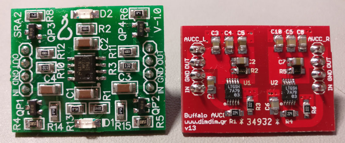
The new boards are direct replacements for the Tridents, supplying 2 x 3.3V for AVCC_L & AVCC_R, 3.3V for the oscillator, 3.3V for the AVDD and 1.2V for DVDD.
Upon powering up the board with the new clock and power supplies, I noticed a problem. Whenever I tried to play material with sampling rate over 44.1KHz, the sound became garbled.
In my test rig I had also used the same power supplies with no problem, so I guessed that the problem had to be the new oscillator. But the new oscillator appeared to be working just fine.
To further complicate things, when I turned off oversampling and the DPLL filter the sound improved (but still sounded bad because I was doing no oversampling).
After some probing and prodding, I realized that my 1.2V supply was sagging below 0.9V when the sampling rates went above 44.1KHz. That should not be happening, since I had set the current limit on my LT3042 regulators to about 125mA with the data sheet specifying the 9028’s 1.2V supply current consumption to 82mA. But it appeared that my 9028 was pulling in a lot more current.
So I disabled current limiting and tried it again. This time everything was working just fine, with no sagging, but my LT was getting hot. Real hot. Like 80 degrees C hot when playing 352.8KHz material. So I did a couple of things. First I desoldered the 1.2V power supply and inserted my DMM in series in order to measure the actual current draw. I got these results:
44.1KHz -> 140mA
DSD64 -> 147mA
DSD128 -> 157mA
352.8KHz -> 200mA
So up to 200mA! No wonder my LT3042 was having a hard time.. I was working it very close to its thermal limits.
I decided to mount it vertically and to add a heat sink to the back of the PCB.
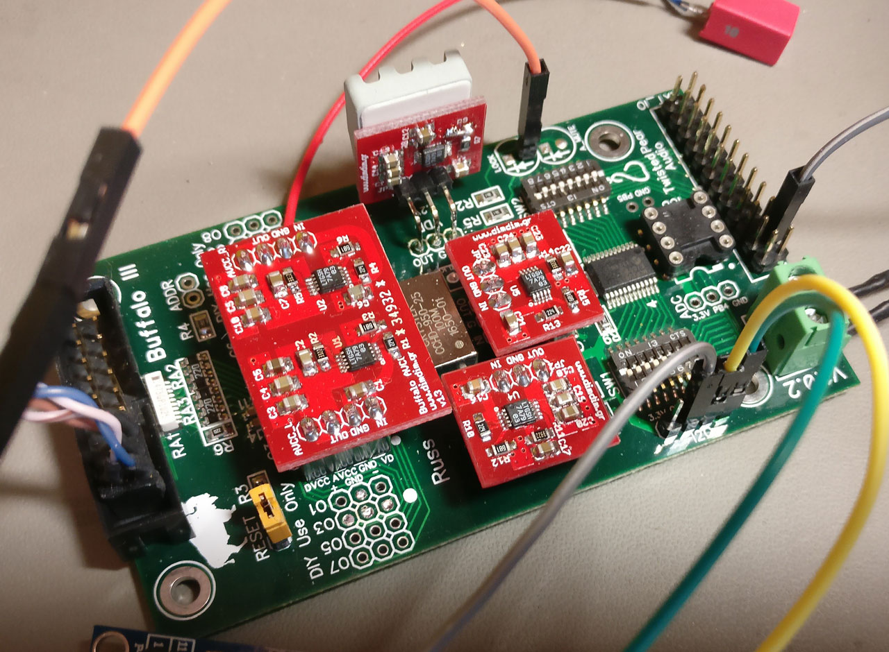
With this arrangement I was getting about 62 degrees C with 44.1KHz material and up to about 75 degrees with 352.8KHz. This is tolerable for 44.1KHz playback but not cool (pun intended 😛 ) for high sampling rates. Since 200mA is pretty much the LT3042’s upper current limit, I’ll have to design a new power supply, either with two paralleled LTs or some other LDO. The bigger problem is the heat dissipation. I will have to make the PCB as big as possible in order to have a lot of room for heat sinking.
But why does this chip’s actual power consumption differ so much from the published specs? As always, the devil is in the details. The stated 82mA is for a sampling rate of 48KHz and a clock frequency of 40MHz. I’m using a 100MHz oscillator so power consumption ought to go up, but I never expected it to increase so much. I wonder what will happen if I input a 768KHz signal.