Linear power supply for the Raspberry Pi: is it worth it?

Pretty much everyone agrees on this one, still, it took me a while to get on the bandwagon. Probably because I am not using an RPi as my main transport..

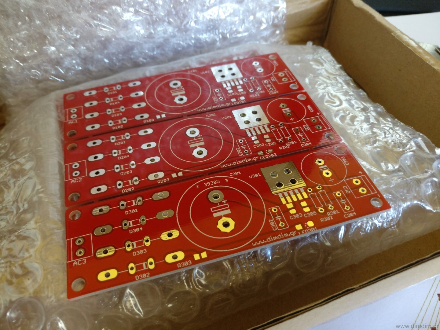
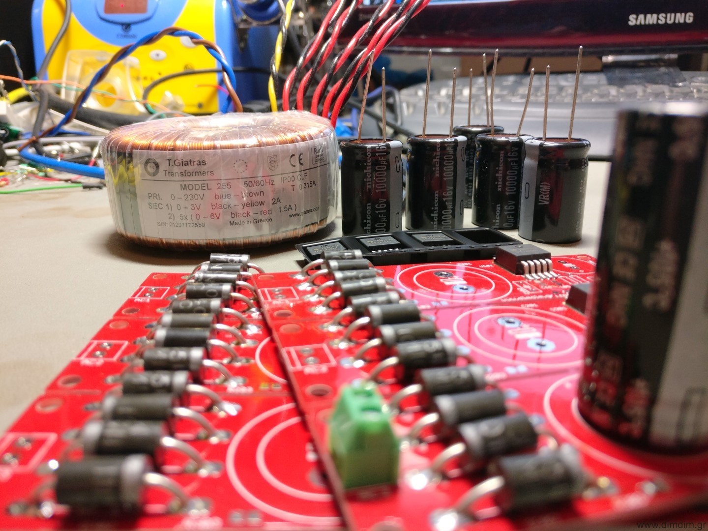
In order to test this I needed a proper linear power supply, capable of outputting at least one “real” amp at 5V. It would also have to be as low noise as possible. After some searching I ended up picking the TPS7A4501 for the job. Since its output voltage is adjustable, it would also come in handy for various projects. So I designed a PCB that would do a proper job of “hosting” the regulators along with the necessary rectification and filtering stages and had a bunch of them made.

I also ordered a proper custom-made toroidal transformer, one that would have 5 secondary windings, each of them outputting 6VAC at 1.5A and one sixth winding outputting 3V at 2A. The end game would be to replace all of the RPi’s on-board switching regulators with linear ones.

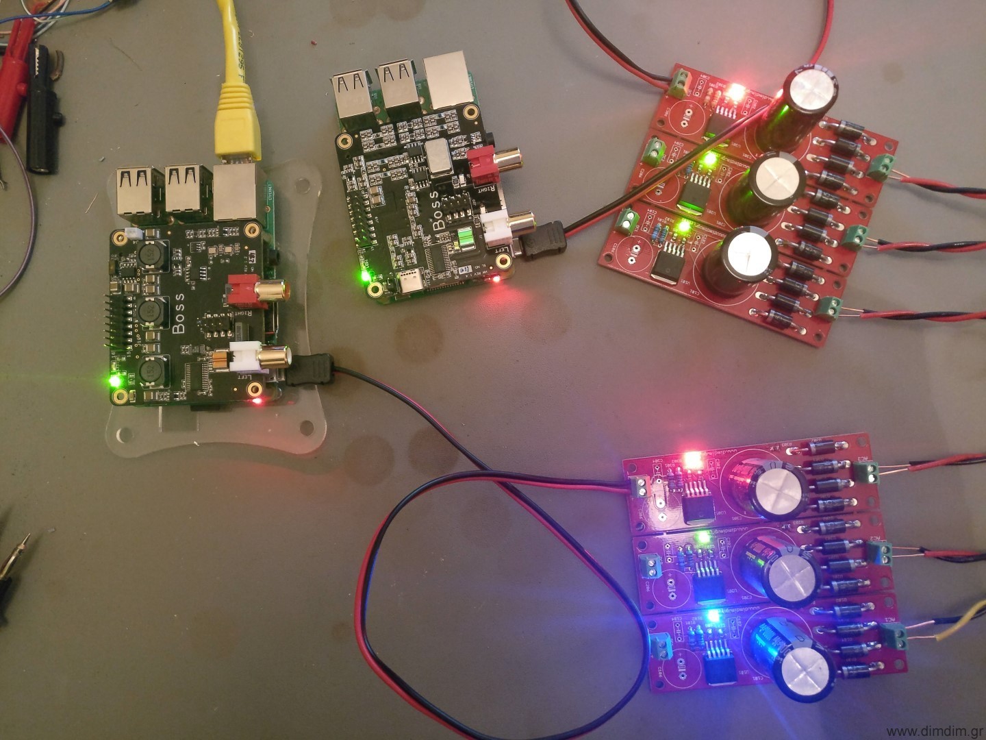
But for starters I’d just power the RPi with 5V via its USB port. Here are a couple of RPi 3s being powered by my linear supplies. This setup would be used to compare the Allo.com original Boss with its new “v1.2” version. More on that in another post.

Power draw on the linear power supply was measured to be at about 500mA @ 5V.

My “reference” 5V SMPS is this one:

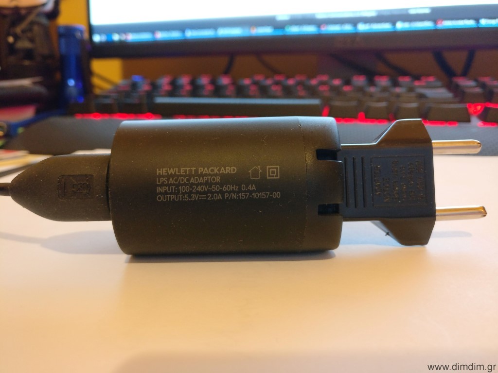
It’s an old but beefy switching mode power supply from an old HP tablet. It’s specc’ed at 5.3V @ 2A.

In order to be as impartial as possible, I took the setup to a friend’s house and had him and a couple of other friends audition the RPi powered either from the SMPS or by my linear power supply.

In both cases, the RPi was running Archphile and was connected to my upgraded-with-ES9028Pro-and-Mercury-Buffalo III DAC via USB.

The difference between the two power supplies was immediately obvious. It was like with the SMPS we had an at-best mediocre source – DAC combination, while with the linear power supply the setup became “proper”, it sounded “in-place” among my friend’s high performing system. The sound stage became better defined, the detail level went up, overall the presentation was more realistic. In other words, it was like the jitter of the system went down, but perhaps the noise levels in the system also decreased.

In other words, IMHO no serious audiophile should be powering his RPi by a run-of-the-mill 5V SMPS, even if he is using it as “just a USB transport”.

Arduino controlled Dual Mono AK4490 DAC (Part 3)

Following up on Part 2, it’s time to talk about the output stage.

This output stage is the brainchild of my friend Kostas, all I did was lay out the PCB.

It is a fully discreet single-ended class-A output stage, outputting ~2.4V RMS.

This is its schematic:

This is the PCB:

And this is the BoM: AK4490 dual mono DAC - Discrete Analog stage BOM (89251 downloads )

The BoM includes part numbers for most parts from Mouser. The only parts that are not in production and must be found elsewhere are the UPA68H. Ebay is a good bet. Chances of getting fake parts are pretty small, but just in case do this to double check the ones that you bought: http://www.diyaudio.com/forums/analog-line-level/296406-salas-dcg3-preamp-line-headphone-post5330311.html (Thank you Salas for the info and the idea to use them in the first place!)

The only parts that need matching are T8A with T9A and T8B with T9B. There’s no need to go crazy with the matching – within 5% should be enough.

Power should be ideally +/-16VDC. A bit less is OK (I did my initial testing with +/-12VDC) but more will most likely damage the board. The board is running in class-A so current draw is constant. A power supply with 100mA current capacity should be enough.

Bias current is adjusted by the multi-turn trimmers R26A and R26B. They should be adjusted to their mid value before soldering to the board (~1K). To adjust bias just measure current consumption at one of the rails while turning the pot. Adjust for ~25mA total current draw per rail and per channel. Current draw on the negative rail should be about 1mA higher than on the positive rail. Bias should be re-adjusted if the power supply voltage needs to change.

After bias adjustment and with no input signal you should check for DC at the outputs. If everything went well you should be seeing anywhere between 0 to a few mV of DC voltage.

A few design notes:

  • This design is inverting. I’ve set up my AK4490 code to also invert the 4490’s outputs so as to end up with a non-inverting overall output. But it doesn’t seem to be making much of an audible difference, since I can’t hear a difference as I’m switching between inverting and non-inverting output.
  • There is provision for a relay that switches between the default filter for PCM (-3db @ ~90KHz) to a more proper filter for DSD (-3db @ ~50KHz). This feature has not been tested yet..

Regarding the resistors, we’ve chosen to go with mini MELF resistors (type 0204) because of their high quality and in general excellent reputation for audio. We are aware that some of the necessary values ATM are kind of hard to source so we’ve included notes in the BoM with the really critical parts and valid value ranges for the less critical other values. Note that “+/-5% from initial value” does not mean that the parts tolerance can be 5% – it means that instead of for example a 10K resistor you can use a 10K + 5% = 10.5K part. It still has to be matched to its counterpart, of course.

I am including these substitutions, as reference:

Instead of the proposed 604R : —-> https://gr.mouser.com/ProductDetail/Vishay-Beyschlag/MMA02040C6190FB300/?qs=sGAEpiMZZMsU0eETUM64Jwu1lXnAfA1Az%2fUBmHPWxBQ%3d
Instead of the proposed 62R —-> https://gr.mouser.com/ProductDetail/Vishay-Beyschlag/MMA02040C5909FB000/?qs=sGAEpiMZZMsU0eETUM64JzhzDaxYafIopmV6xoU7Pd%2faEeFyYr39dw%3d%3d
Instead of the proposed 49,9R —-> https://gr.mouser.com/ProductDetail/Vishay/CMA02040X3909GB300/?qs=%2fha2pyFaduinSoUQ%252bxM%252bcspKJgxV2WgydeZC1mFkJQ0%3d
Instead of the proposed 499R —-> https://gr.mouser.com/ProductDetail/Vishay-BC-Components/CMA02040X4700GB300/?qs=sGAEpiMZZMsU0eETUM64J9XrXp4g00LTnadULizxluo%3d
Instead of the proposed 33R —-> https://gr.mouser.com/ProductDetail/Vishay-Beyschlag/CMA02040X3309GB300/?qs=sGAEpiMZZMsU0eETUM64J5DAE%2fHuiq02KfqnEeQjWns%3d
Instead of the proposed 10R —-> https://gr.mouser.com/ProductDetail/Vishay-Beyschlag/CMA02040X1009GB300/?qs=sGAEpiMZZMsU0eETUM64J5wRh77yguxgpX8F3yMYvKE%3d

The value of two of the required 1K resistors (the R20A & R20B) is critical, so you should use these —-> https://gr.mouser.com/ProductDetail/Vishay-Beyschlag/CMA02040X1001GB300/?qs=sGAEpiMZZMsU0eETUM64J5DAE%2fHuiq026nqxTapoB%252bc%3d
for the other 6 non-critical 1K resistors you can use these —-> https://gr.mouser.com/ProductDetail/Vishay-Beyschlag/CMA02040X1201GB300/?qs=sGAEpiMZZMsU0eETUM64J5DAE%2fHuiq02Tdrq8lX57XI%3d

The value of the 120R resistors is critical, so are the tolerance of the 49.9R (substitution for 39R) resistors. Their values should be matched.

This concludes Part 3. The next post will detail how everything works together.