
UPDATE (30/11/2013): Here is an easier way: https://www.dimdim.gr/2013/11/3-2%E2%80%B3-tft-connection-to-arduino-due-update/
Still, keep in mind that the info posted below still applies and is probably useful..
I’ve been asked what is the correct way to wire a 3.2″ TFT to an Arduino MEGA (or Due) in order to make it work with the UTFT library.
The answer of course depends on the exact model of the TFT that we have on hand. The below instructions apply to a generic 3.2″ TFT with wide aspect ratio and resolution of 240 x 400 that I got off of Ebay.
This is its pinout according to the manufacturer:

This is nice, but I want to use a standard 40-pin ribbon cable which I have left over from an old computer, and its conductor numbering is a little different. At first I thought I’d try to make sense of it as I went but it didn’t take long for me to realize that it would actually save me time if I made a “conversion table”. So I came up with what you see here:
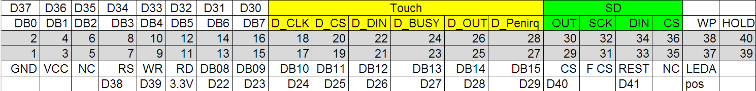 What we have here is the actual conductor number in the grey background (counting the conductors in the ribbon cable from left to right) and then above and below them the corresponding signal lines according to the above pinout. Above and below the signal lines I have noted the actual Arduino pins that correspond to the signals.
For example, pin 2 (the second pin on the flex cable looking at it from the left) corresponds to the DB0 signal which should be connected to the D37 pin on the Arduino MEGA (or Due). Note that the connections are made according to UTFT’s documentation and are applicable specifically to UTFT.
So we have to connect signals D0 through to D15 to the necessary digital pins. Then we also have to connect pins RS, WR, CS and REST to whichever pins we like (we must declare these pins in our sketch, see UTFT documentation). Pin 11 is RD and it must be pulled high, which means connecting it to +3.3V. Pin 37 is the backlight illumination which means it must also be connected to +3.3V. This leaves pin 1 which must be connected to ground and pin 3 which must be connected to Vcc which in our case is 5V.
Note that I have not really gotten around to using the touchscreen capabilities or the SD reader, so I have not connected them to my Arduinos. It shouldn’t be difficult though.
Now, there is one more thing that I should point out and it is very important. The Arduino MEGA is using 5V logic while the TFT is expecting 3.3V logic. This means that if you connect the D0-D15 and RS, WR, CS, REST lines directly to the MEGA you will most likely damage the TFT. You need to connect a 10K resistor in series with each and every one of the lines. That will bring the voltage down to acceptable levels. Do not forget to do this!
In case of the Due the resistors are not necessary since it uses 3.3V logic so it is directly compatible.
Here is a little video I made of the 3.2″ TFT running a UTFT demo sketch:
Good luck!
Hi DimDim
Nice Page and Idea for helping others! 🙂
I’ve also bougth an Arduino DUE and a 3.2″ TFT LCD from elechouse but I can’t download the examples to the Board.
I have the latest version 1.5.5. of the Arduino Software and downloaded all the 3 library packages, but there are these errors:
I really have no more idea how to fix it and tryed it more than 2 hours 🙁
Hope you can help me.
Thank you and have a nice weekend!
Patrick (patrickrickenbacher@gmx.ch)
Arduino: 1.5.5-r2 (Windows 7), Board: “Arduino Due (Programming Port)”
C:\Program Files (x86)\Arduino\libraries\tft_shield_master\tftlib.cpp: In constructor ‘TFTLCD::TFTLCD()’:
C:\Program Files (x86)\Arduino\libraries\tft_shield_master\tftlib.cpp:8: error: no matching function for call to ‘Adafruit_GFX::Adafruit_GFX()’
C:\Users\Pat\Documents\Arduino\libraries\Adafruit_GFX_Library/Adafruit_GFX.h:17: note: candidates are: Adafruit_GFX::Adafruit_GFX(int16_t, int16_t)
C:\Users\Pat\Documents\Arduino\libraries\Adafruit_GFX_Library/Adafruit_GFX.h:13: note: Adafruit_GFX::Adafruit_GFX(const Adafruit_GFX&)
C:\Program Files (x86)\Arduino\libraries\tft_shield_master\tftlib.cpp: In member function ‘void TFTLCD::begin()’:
C:\Program Files (x86)\Arduino\libraries\tft_shield_master\tftlib.cpp:40: error: ‘constructor’ was not declared in this scope
This report would have more information with
“Show verbose output during compilation”
enabled in File > Preferences.
Would you mind showing your pin interface? or send me an email with some type of picture or diagram with it? I think buying the shield is pointless because i have more going on with my arduino than just a TFT, I would appreciate any help you could give!
thanks again!
Oh I am sorry i completely missed the explanation above! thanks i have gotten it working!
hi,
I tried to wire a 3.2 TFT Display that I bought on ebay.
but I have a problem:
After wired the display I obtain this result
https://plus.google.com/photos/yourphotos?utm_source=chrome_ntp_icon&utm_medium=chrome_app&utm_campaign=chrome&pid=6022143023993165682&oid=105885934844744899968
sometimes the display don’t run.
can you send me some solution to resolve it?
the pin map is similar to your
thanks
I’ve mentioned this elsewhere – but a note of caution.
DimDim’s pin numbering is correct for his notes and the Sainsmart PCB…
BUT SainSmart **does not use either of the standard ‘conventions’** for pin numbering of IDC/BERG style connectors. It looks like the PCB designer took a standard 20×2 footprint and used it on the rear of the board without flipping the pin designations.
Just a catch – as every pair of two pins are alternated – which means you must be careful at the Arduino end of the cable !!
hi
i have put 0ne 10 k resister to one of my arduino2560 pin make that pin high and check with multimeter it was still 5V so its safe to connect to my 3.2 ” 40pin TFT..
Hi there,
It is definitely not the best way of doing things but it limits the current just enough so that it does not cause damage. A more proper solution would be a voltage divider built with 2 resistors, but that would not be easy to do without a PCB. The best solution would be to use level shifting ICs, but we would definitely need a PCB for those.
To be totally honest, IMHO the best solution would be to retire the MEGA and go for a DUE.. 3.3V logic and fast as hell which is particularly useful when driving an LCD. Also practically same price with the MEGAs.
Hi.
Following your good explanation I cabled my 3.2 tft and it’s now working well.
But…there’s a problem.
The touch function doesn’t work. I wired the five pins (TCLK, TCS, TDIN, TDOUT, IRQ) as described on many websites that talking about this.
I’ve tried all the sketches from the UTFT TOUCHE library. All were loaded right on Arduino but the display doesn’t receive the touch of fingers.
Any suggest?
Hello,
I’m afraid that I have no experience in using the touch functionality of this TFT (or any TFT for that matter..).
OK. I understand. But in your opinion the five pins that drive the touch should be connected to 3.3 or 5 Volt like pins from D0 to D15? I have this doubt.
If you’re using a DUE, it would make sense to use just 3.3V throughout the project. Otherwise you would be looking for trouble..
Put only 10 ohm resistor, if you put 10k it doesnt work whatsoever
one question, were you able to make the screen work with the touch? can you pass me the diagram?
I’m afraid that I still haven’t tried using the touch functionality and it doesn’t look like I will be trying to in the future. I’ve moved away from using this type of LCDs.. Nextion screens are way easier to work with.
Great post! Followed your directions (including putting a 10K resistor in series with each line) and it worked perfectly the first time after wiring it up to my Mega 2560. Thanks, you made it easy!
You’re most welcome, Warren!
Good night, you could provide the schematic ? I am following the tutorial, but I am finding it difficult , and the code also to be able to have a refrence , I thank you .
Hi there! Which schematic and code are you referring to? Also, have a look here for an easier way to make the cable: http://www.dimdim.gr/2013/11/3-2%E2%80%B3-tft-connection-to-arduino-due-update/
hello, I have followed your tutorial, and the screen is white no matter the sketch I upload, can you please resend the sketch and library you used? thanks. also I am using 3.2″ tft lcd module 16bit, ili9134 model
Are you sure that it is a 10K resistor? I think it should be a 10 ohm resistor, because a 10K resistor disipates too much power.
Mastodon, beast, dude, savage, wild Arduino man that doesn’t know about the Kirchoff’s law
With love
hello, I have followed your tutorial, and the screen is white no matter the sketch I upload, can you please resend the sketch and library you used? thanks. also I am using 3.2″ tft lcd module 16bit, ili9134 model
auto correct-> ili9341
Hello, I actually have got the screen working, but I changed some code of the library
auto correct-> ili9341
Hello!
Excellent tutorial, I have a question, did you connect the display directly to the arduino or did you use a 5 to 3.3v TTL converter?
Thank you for your kind words. 🙂
When interfacing to an Arduino Due I just connect the display directly.. When using a MEGA I insert 10K current limiting resistors in series with each of the data lines. This keeps the display’s controller from getting damaged. I know that it’s not exactly the proper way of doing things, but since it has worked for countless people on the Arduino forums, I chose to go ahead this way.