
About a year and a half back, while watching a mailbag clip from EEVblog, I learned about the uRADMonitor project by Radu Motisan.
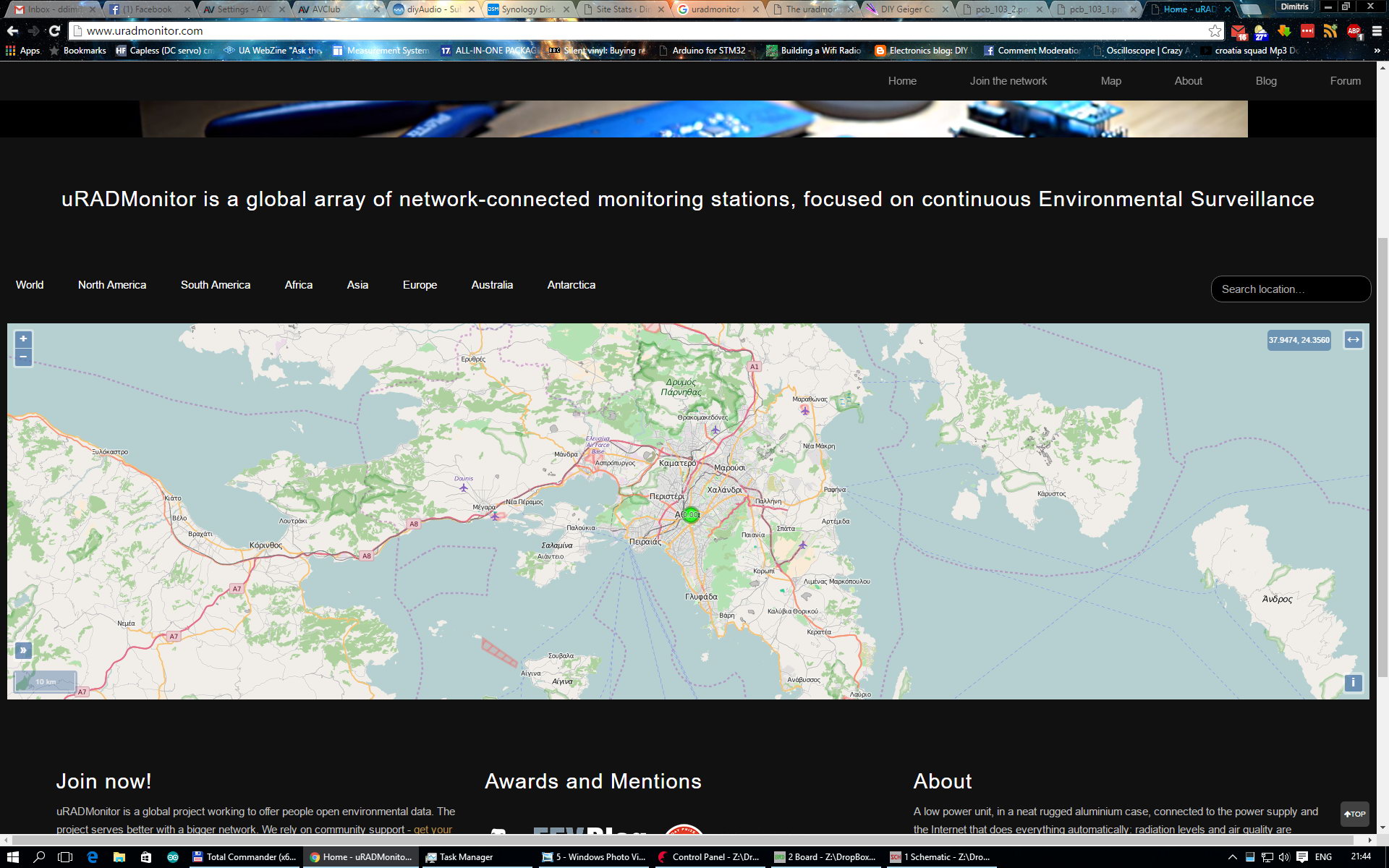
The idea was to build a network of monitoring devices all around the globe that would measure radiation levels and display the results on a global map.
I noticed that there existed no data for Greece, so I thought I would fill that gap in the map. I enquired about a uRAD measuring unit but realized that it was kind of pricey (~$200 for a finished unit) so decided to wait for the Indiegogo campaign that had already been announced.
The campaign ran successfully, so I ended up owning a uRADMonitor KIT1. These are the contents of the kit:
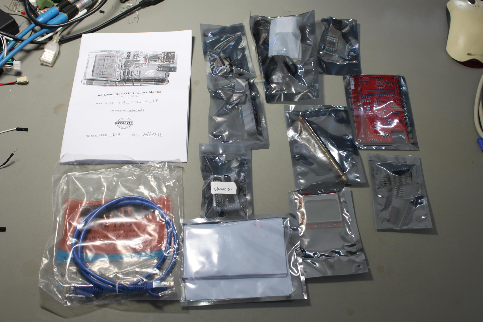
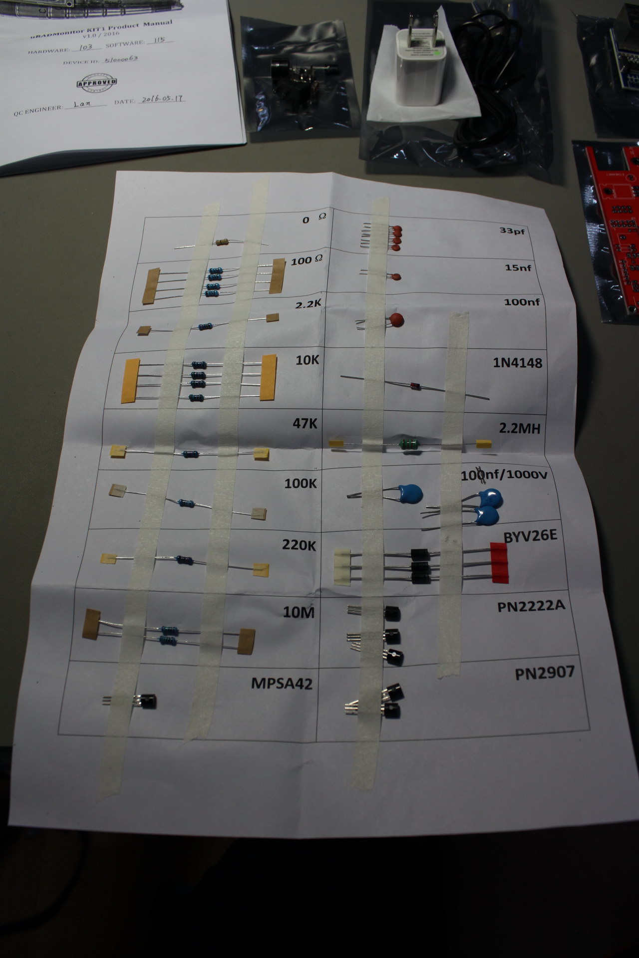
The smaller components come nicely sorted and taped to a piece of paper:
The PCB itself is of typical quality:
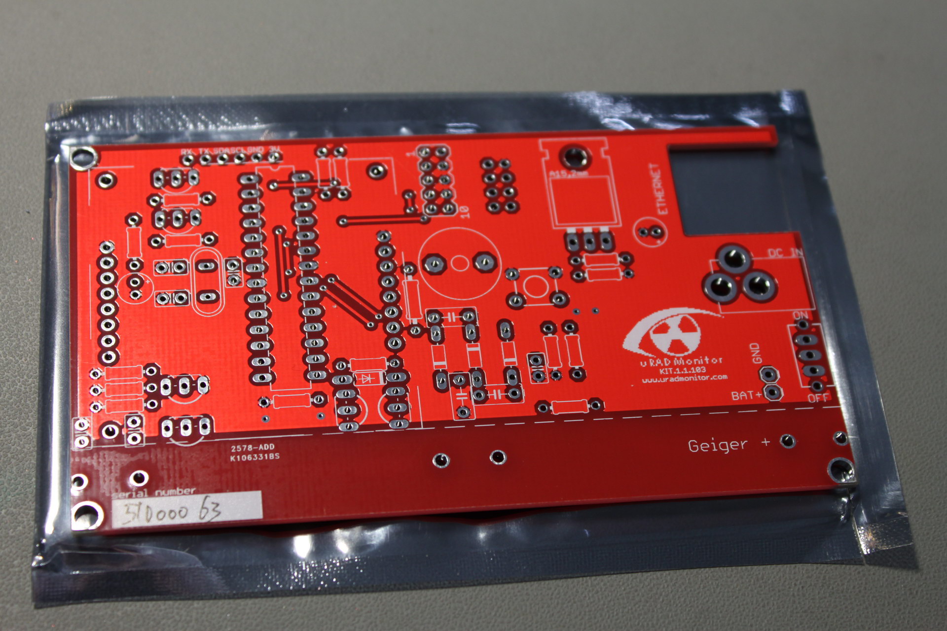
You might notice that there is no silkscreen detailing the names of the components. I hope Radu changes that in future revisions of the KIT1.. It would make building the kit a lot easier.
The kit comes with a pretty nice manual. In the manual among other useful info you can find a parts placement diagram:
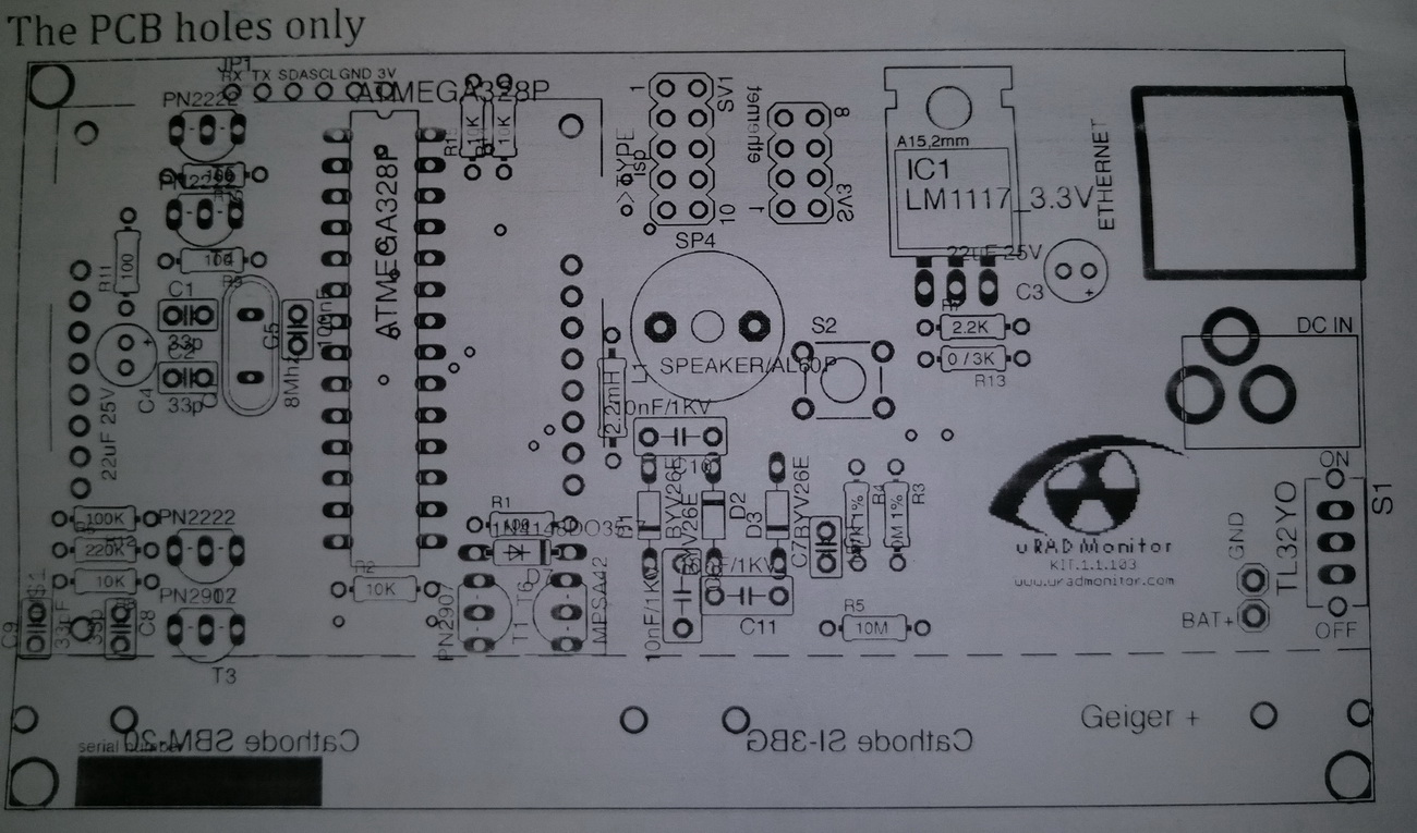
..and a BoM:
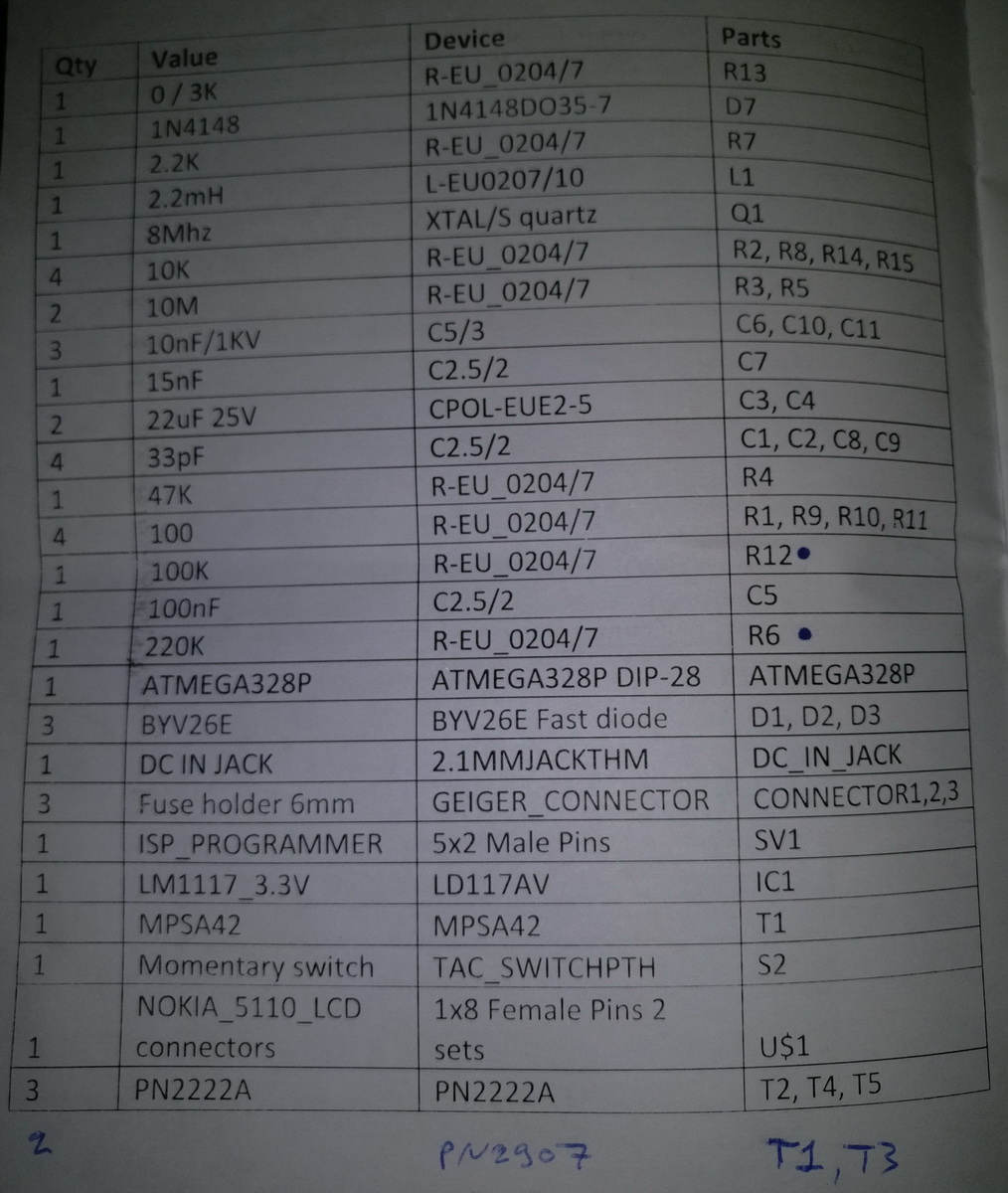
You will notice that I have added a couple of transistors to the bottom of the BoM. They appear to have been left out of the BoM by accident. No biggie.
To actually build the kit one has to correlate info from the parts placement diagram and the BoM. It’s not really difficult to do, but it might trouble a novice in electronics.
We start by soldering on the lowest-profile components. That means the resistors, the diodes, the inductors, the ceramic capacitors, the IC’s socket, the crystal and the push-button.
We continue with the transistors and the voltage regulator IC. Take care to follow the instructions here – R7 should be left open (no component) and R13 should be shorted.
Next up is the on/off switch and the terminals that will hold the Geiger tube.
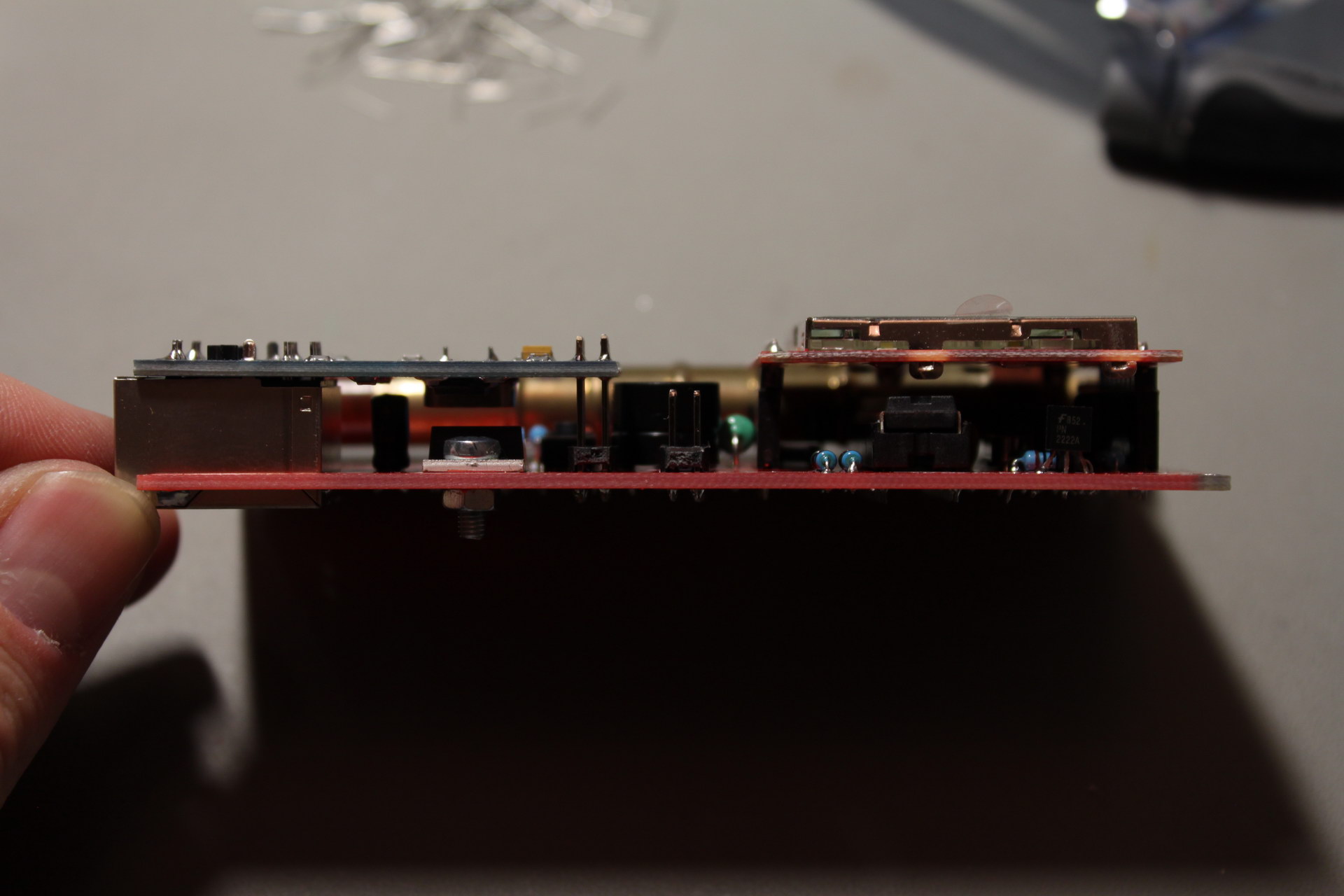
We then move on to the piezo speaker (be careful, it is polarized!), the pin headers for the display and the ethernet board and the power input jack. Regarding the ethernet board, you will need to take care to mount it properly on the first try because it will be soldered in place. You are supposed to mount it in such a height and angle so that it is perpendicular to the main board:
You can power the board with the supplied power supply or any 5VDC power supply. The power switch turns on when it is toggled towards the Geiger tube:
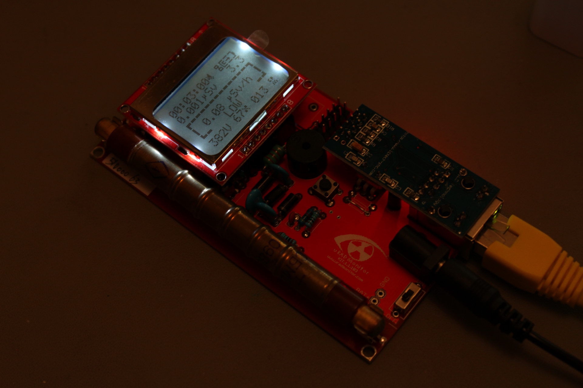
The Atmega328 that comes in the kit is already pre-programmed with a unique identifier for your unit so all you have to do is connect the kit to your router with an ethernet cable and it should get an IP from your DHCP server. Once that is done, it will automatically appear on uradmonitor.com:
Here is my unit powering up:
uRADMonitor may have begun with measuring radiation levels but it is evolving into a more diverse platform, measuring several other pollution factors. I’ll be happy to incorporate more sensors into my KIT1 in due time.