Kali FIFO Buffer & Reclocker for SBCs

kali_on_bench

Back in August an interesting thread was started on diyaudio.com.

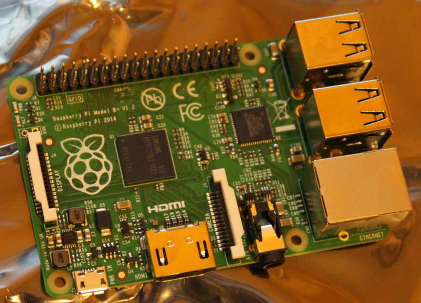
It described a FIFO buffer and reclocker, aimed at SBCs and more specifically the RPi.

Its name was Kali.

The FIFO board would be able to “fix up” the RPi’s problematic I2S output so as to improve the sound quality of the used DAC.

As the discussion progressed, more interesting details came to light.

Kali was basically an FPGA design with on-board RAM, high quality clocks and flip-flops. It would buffer the DATA stream in RAM (about 0.7 seconds of audio) and it would then reclock it using flip-flops outside of the FPGA. The clocks used for the reclocking would be high quality NDK units sporting extremely low phase noise.

It would be powered by a 5V/3A power supply and would supply filtered power to the RPi (or not, selectable by a jumper) as well to the DAC that would sit on top of Kali.

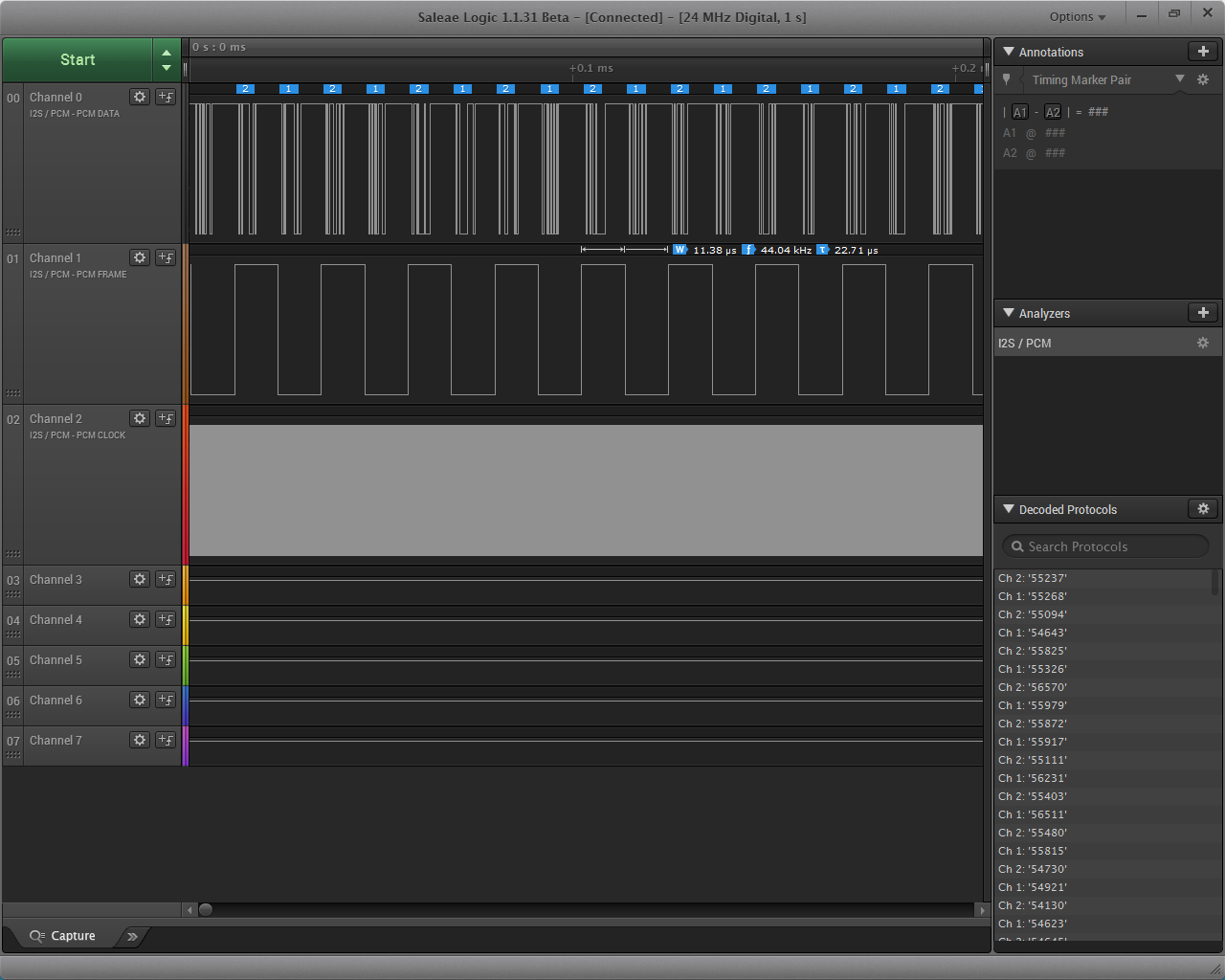
It would have a claimed 3ps of jitter, which is an impressive feat for any I2S source.

It would provide a high quality MCLK output from a U.FL jack underneath the board.

The board’s general availability was scheduled for the end of August, and its price would be in the neighbourhood of $70.

At around mid August cdsgames offered to give away a number of units to diyaudio members for testing. I took him up on his offer and he was kind enough to send me one (along with a Piano 2.1 DAC board, but that’s for another post).

Fast forward to mid-September, when I received a package from India. In it was Kali and Piano 2.1 (more about that in another post).

kali_in_packaging

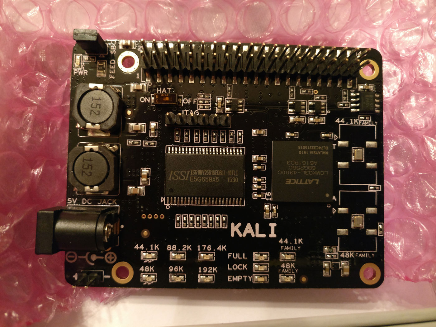
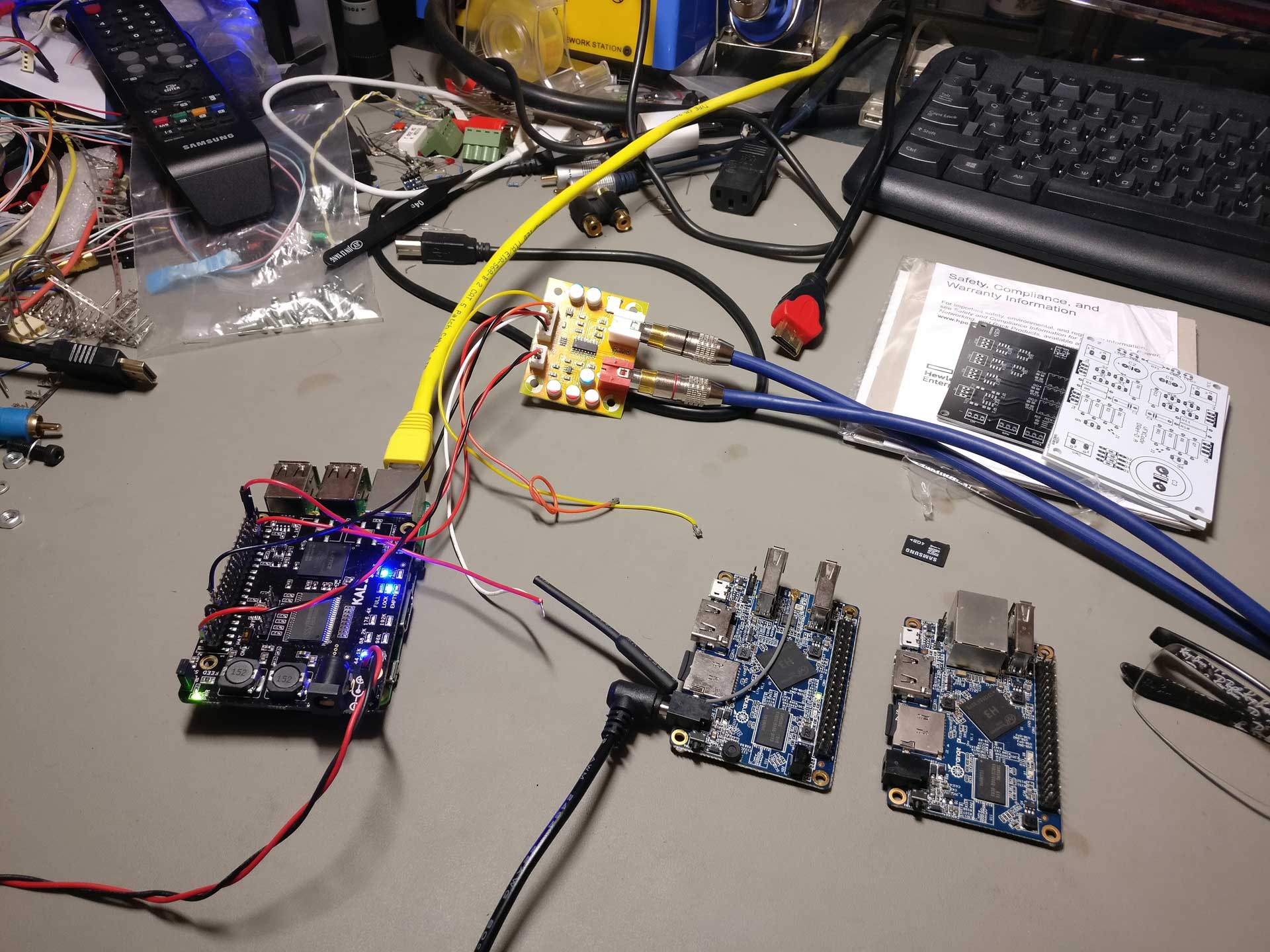
On the left side of the board we can see the DC IN jacks (barrel and pin header), plus a couple of inductors that help with filtering the power lines. On the top left there is a jumper that controls whether Kali will supply power to the RPi or not. The Kali lists as minimum requirement a 5V/3A power supply. However, Kali itself will consume only about 100mA. The rest of the power is intended for the RPi and the DAC board. Note that Kali is designed so that it powers the RPi and not the other way around.

In the middle of the board the two chips that dominate are the 4Mbit SRAM chip and the Lattice MachXO3L-4300 FPGA itself.

To the right we have the two NDK clocks, one for each one of the two “families” of sampling rates.

kali_clock

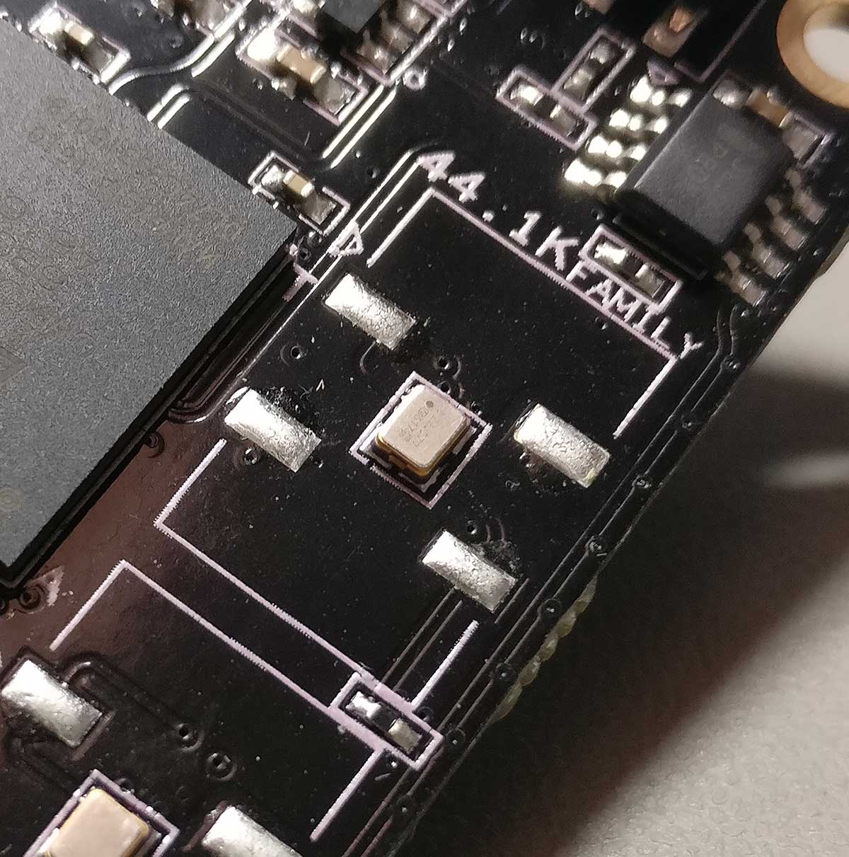
The Kali comes in two versions. One with clocks at 22/24MHz, capable of supporting sampling rates up to 192KHz, and one with 44/48MHz clocks, going up to 384KHz.
Note that there are two footprints available for the clocks so that a curious (and somewhat experienced) DIYer can also try out clocks with different footprints, like for example Crystek units. If you choose to go that way, keep in mind that you will also need to change 2 capacitors from 0.01uF to 0.1uF.

At the top of the board we have the usual 2×20 header that reproduces the RPi’s GPIO pins. There is one notable exception – Kali does not supply 3.3V at the relevant pin, so if your DAC needs to take 3.3V from that pin it will not work (more on that later).

Note that even though Kali has a JTAG header, the manufacturer currently does not support firmware upgrades. That’s understandable.. JTAG is not for consumer use and the manufacturer has to protect his IP..

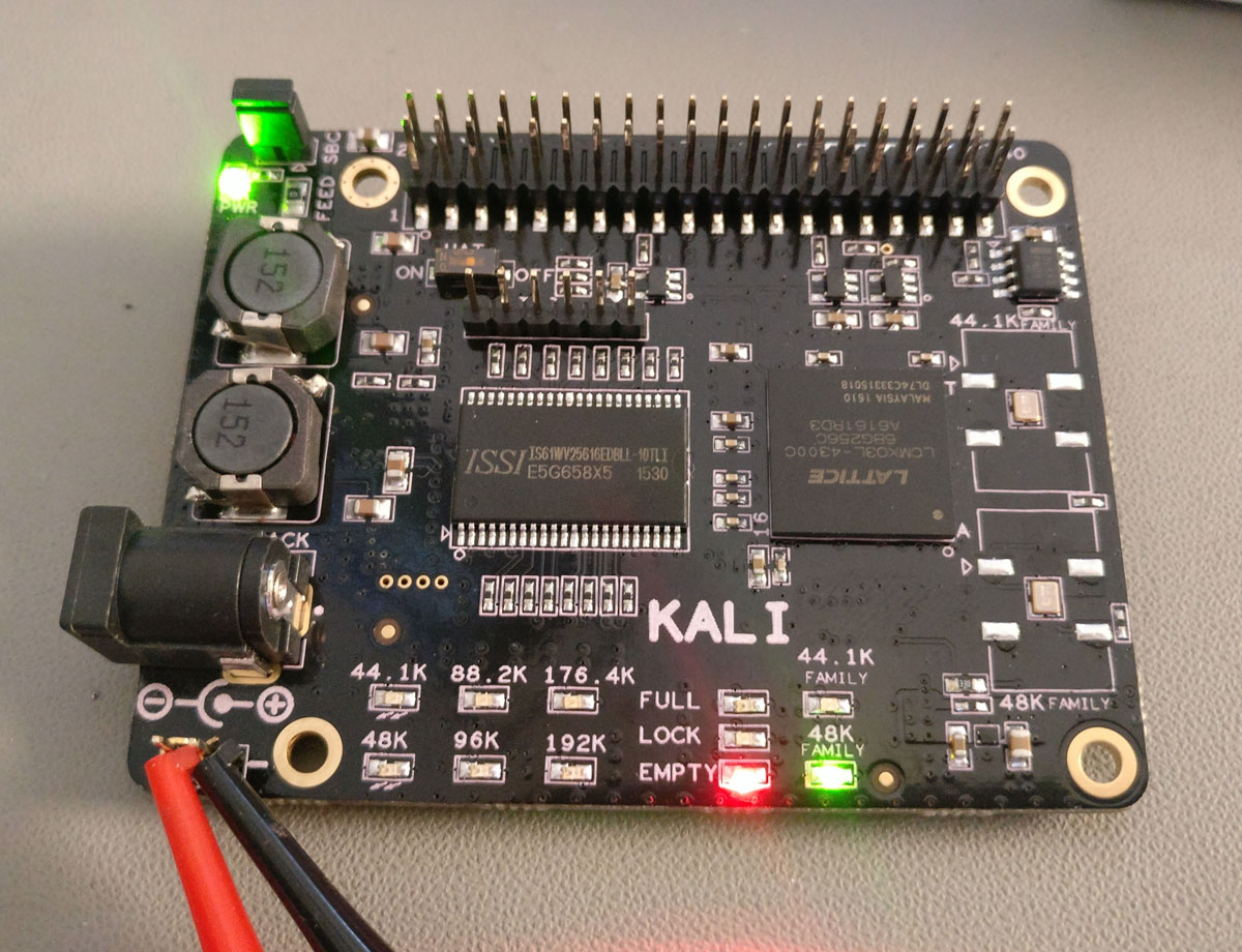
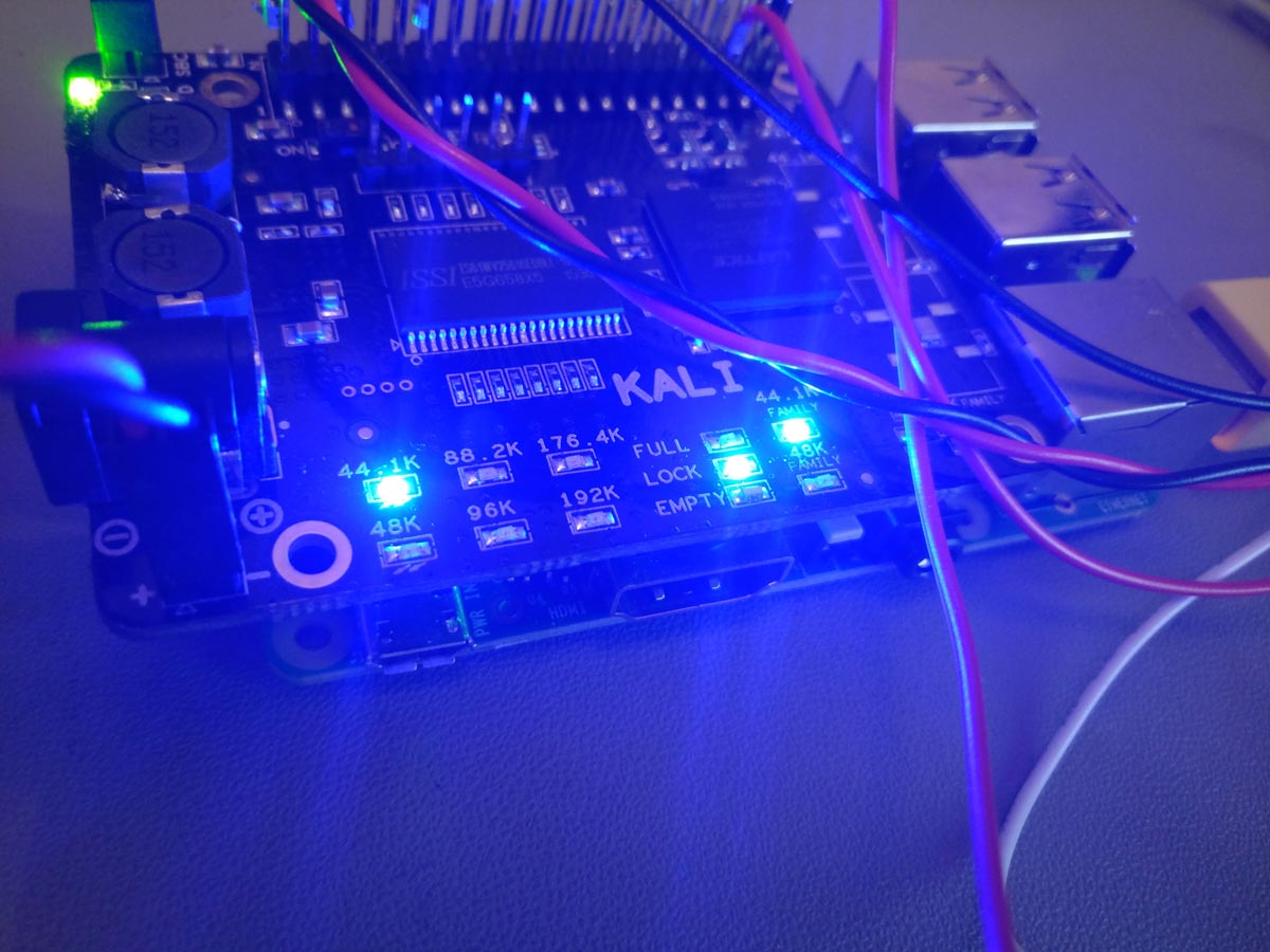
At the lower end of the board we have an array of LEDs indicating the sampling rate of the incoming signal, along with the status of the buffer (Empty / Full / Lock) and the selected oscillator.

kali_lights_on_44-1k

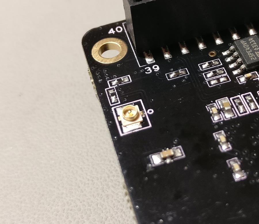
At the bottom of the board there is a U.FL socket that outputs Kali’s MCLK.

kali_mclk_out

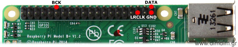
So, we have an RPi, we have Kali, now what we need is a DAC. Kali will put a few restrictions on your DAC choices. Your DAC will have to run as “slave” to the RPi, that is it will have to take its BCLK from the RPi and not the other way around. Examples of such DACs include for example virtually all of the DACs based on ES9023 chips. DACs that are designed to run as masters (in order to battle the RPi’s legendary jitter problem), such as the Hifiberry Dac+ Pro & Digi+ will not work, at least not without some extra work.

Plus, like I mentioned earlier, Kali does not supply 3.3V on its top 40-pin header, so if your DAC requires that voltage you’ll need to find a way to supply it externally.

Straying a bit from the DAC HATs, Kali will have no problem feeding pretty much any DAC that accepts standard I2S, like for example a TPA Buffalo DAC.

kali_buffalo_iii

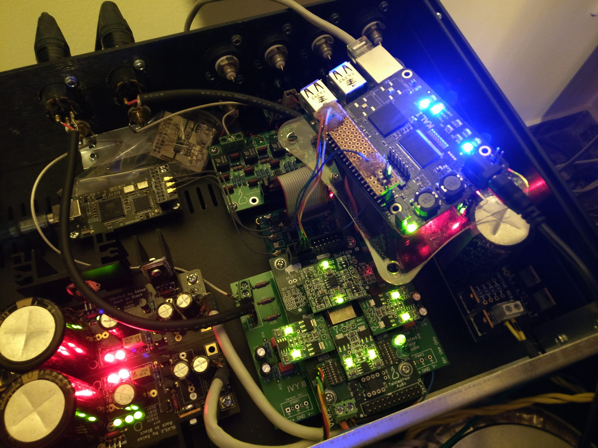
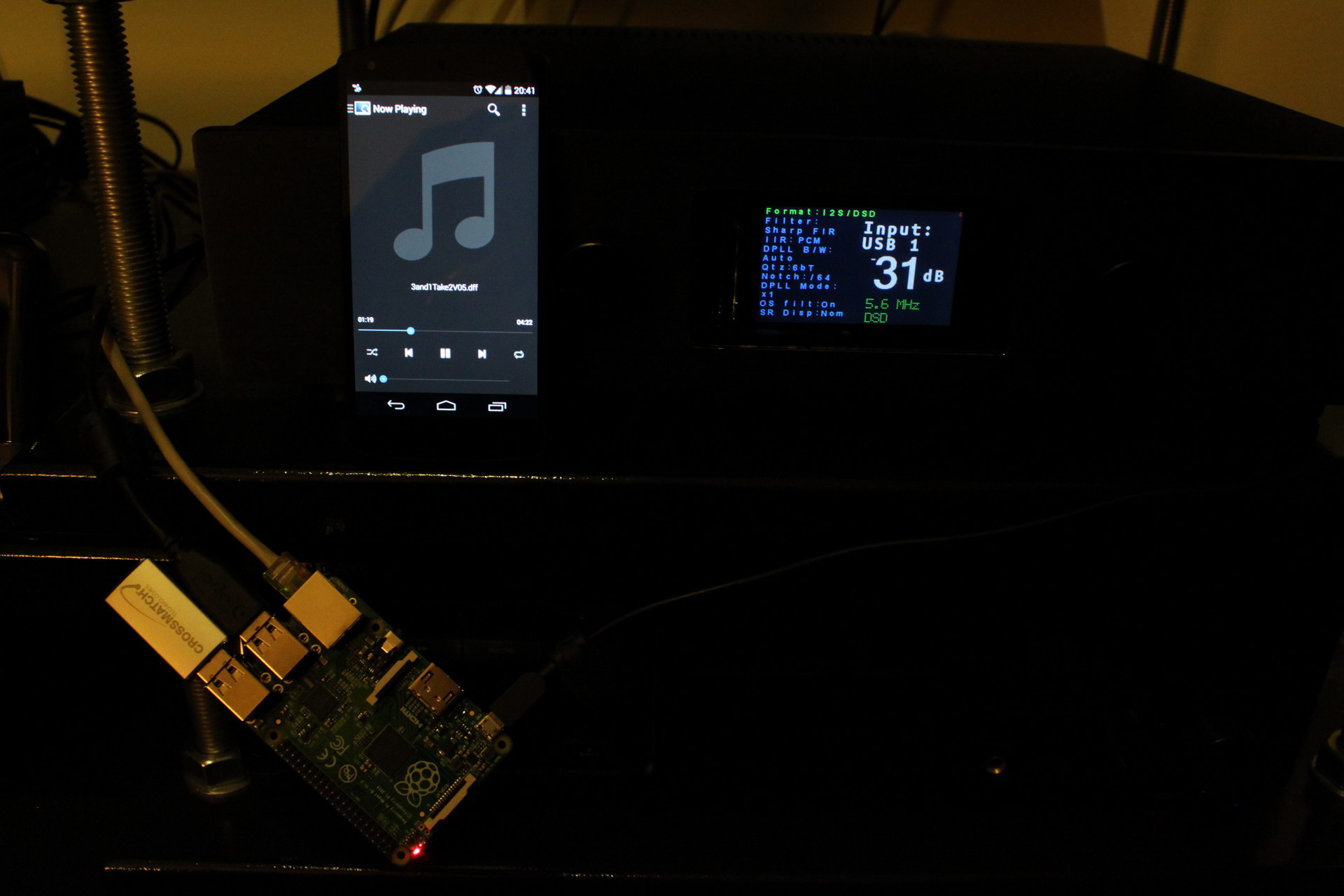
As a matter of fact, in my system Kali did a remarkable job of improving my RPi’s I2S output. The difference was obvious immediately. My RPi went from being a “net streamer quality” source to giving my Amanero a run for its money. Remarkable.
I am not talking about differences in bass or treble or tonality. It is like Kali manages to extract more music content from the data files. It revealed details that were there but were not audible. The music became more “real”. Imagine going from SD TV to HDTV. And that with the same 44.1K/16bit source material.

This improvement is not apparent only on expensive gear either. My first tests were done on my workbench with my RPi feeding an $8 9023-based DAC and listening through my headphones.

kali_tests_workbench

Even with this setup, Kali made a significant improvement to the sound. The $8 DAC went from sounding like an $8 DAC to performing at least decently. It was an obvious improvement.

So I can not imagine a scenario in which the Kali will not make an audible improvement to the sound.

Note that the first batch of Kalis (the ones that were sent to reviewers and a small number of units that were actually sold) had a bug that caused 16bit audio to have its channels reversed (and some more weird stuff happening with their I2S output resulting in somewhat degraded sound quality), but according to allo.com all effected units have been exchanged with fixed ones plus the ones that are shipping now to customers come with a fixed version of the firmware.

Even if for some reason you come by an affected unit, all you have to do is tell your RPi to output 32bit audio. That will fix everything.

I’d like to thank Ioan (cdsgames at diyaudio.com) for sending me the remarkable Kali. It will for sure become a permanent part of my audio chain.

At the time of this writing, Kali is being sold directly from its manufacturer’s site (allo.com) as well as from Volumio’s online shop.

HP Proliant Microserver Gen8

I’ve been a fan of HP’s Microserver line for many years. I bought my first one in 2011, my second one in 2013 and my third one a few days ago. All of them are running non-stop since I bought them. They have proven to be true Proliant servers, in the sense of having good reliability and build quality.

But the latest one (Gen8) is by far the most “Proliant” of them all (more on that later).

2015-12-22 00.39.59

Let’s start by getting the specs out of the way. I bought the 819185-001 model, which comes with:

  • One Intel® Celeron® G1610T (2.3GHz/2-core/2MB/35W) Processor
  • 4GB (1 x 4GB) PC3L-12800E DDR3 UDIMM
  • HPE Ethernet 1Gb 2-port 332i Adapter
  • HPE Dynamic Smart Array B120i Controller
  • 150W Non-Hot Plug, Non-Redundant Power Supply
  • HPE iLO Management Engine

It has pretty good connectivity, since it comes with 7 x USB ports (2 of them USB 3.0), 3 x GbE Ports (one of them is the dedicated iLO port, more on that later), one PCIe x16 slot, etc.

2015-12-21 19.18.20

It supports 4 internal HDDs and an internal slim DVD-RW drive. Since it is 2016 (no-one needs DVD-RW drives any more), I decided to make better use of the server’s fifth SATA port by using it to connect an SSD system drive. Getting the SATA cable from the mainboard to the top of the case was no problem, but powering the SSD was. The server has a spare power connector, but it is meant to power HP’s DVD-RW drive which (oddly enough) has an old floppy drive power connector. I did not want to cut the cable and splice in a proper SATA power connector, so I did the sensible thing. I robbed an old floppy drive of its most precious component: Its power input jack.

2015-12-21 19.31.57

I made sure that it mated properly with the server’s connector.2015-12-21 20.21.48-2

And I soldered on an old SATA power cable I had. I used heat shrink tubing (of proper colors of course :P) to make sure that there would be no possibility of shorts.2015-12-21 20.38.092015-12-21 20.40.17

So now I had my SSD installed and it was time to install the OS.

2015-12-22 00.29.17

This is where things get interesting. Remember, this is a proper Proliant server. What this means is that it has a pretty strict operating system compatibility list, and no consumer OS are officially supported. So, Windows Server 2012R2 and 2008R2 are OK, Windows 8.1 is not. I normally run Windows Home Server 2011 (which is based on Server 2008) so I should be OK, but I decided to get started with a trial of the full fledged Windows Server 2012R2 (just for the experience..).

Installing an OS is supposed to be a simple procedure. HP’s Intelligent Provisioning takes care of drivers and server applications for you, but before you get to that there are a number of things to do.

We are dealing with an actual server here, so inexperienced users should definitely start by reading the manual or at least the quick start guide that comes with the server. If you do not do that, you should not expect to get very far. You will waste a few hours, wondering why Windows is not installing and what you are doing wrong.

One of the first things to do is to decide whether you want to make use of the server’s Dynamic Smart Array RAID controller of not. You have a choice. You may run it either in AHCI mode (a.k.a. “dumb mode”) or in RAID mode. There are merits to either mode. If you go the AHCI route, you will get to keep your drives’ existing data (which would be wiped clean if you went the other way) and that data will be visible from other machines if you decide to take the HDDs out and put them inside some other machine. So the main drawback is noise. That’s right, the server’s main fan will run a lot quieter if you set your Smart Array controller in RAID mode. In fact, this way it will run even quieter than the previous generation of Microservers. I chose to go this way. So, first order of business is to create an array. You may create a RAID0 or 1 array if you have 2 or more drives or RAID0 if you have one. I would have a number of drives in my server, but I did not want redundancy, so I started with one RAID0 array consisting of my SSD system drive.

2015-12-21 21.01.31

Next up was a firmware update for the server’s subsystems. There is a bewildering array of firmwares that may need updating. Good thing that the process is automatic and is done from within the server’s BIOS, before you install the OS. The same goes for driver updates – they are downloaded automatically before the OS installation begins. Note that the firmware & driver updates come from HP’s web site (obviously..), so you should have at least one ethernet cable connected to your ethernet switch. The server will use DHCP to get on your network. Keep in mind that the firmware update when done this way is actually not very effective, meaning that chances are that there are newer versions of your firmwares available from HP’s site, but you should not worry about that just yet.

Do use HP’s Intelligent Provisioning to install your OS of choice, preferably from a USB installation medium. I know that there exist unofficial (and thus unsupported) ways to install non-supported operating systems, such as Windows 8.1, but I have not done any serious research into them. YMMV.

2015-12-21 21.46.51

The server will reboot (several times actually..) and you should be patient. Each reboot takes more than 2 minutes, since the server does extensive testing of its subsystems (processor, memory, controllers, iLO, etc).

2015-12-22 20.17.38

You may have noticed that I now have 8GB of RAM installed. I added a 4GB ECC DDR3 DIMM that I had bought for my first Microserver (from 2011). I no longer see the “Genuine HP Memory” message since it is (if I remember correctly) a Kingston DIMM, but I do have twice as much memory, so I can live with that. This memory stick is not officially supported, and it is a bit slow compared to the one that came preinstalled, but it works just fine and 8GBs of RAM offer much better overall performance than 4GBs.

Once you have Windows installed, you should got to HP’s site and register your server. This way you will have access to official support plus HP’s up-to-date ISO file (Service Pack for ProLiant) with all the latest drivers, firmwares, etc. You should mount that ISO image and install the relevant software. You will get useful tools for managing your Smart Array controller, making firmware and driver updates, viewing logs, etc.

You should also make use of your iLO 4 system.

2015-12-21 19.19.10

It will give you remote access to your server’s console without having a monitor connected (up to the time that the OS loads) and a bucketload of diagnostic information such as fan speed, temperatures, etc.

Gen8 temperatures

Once I had the OS installed, I moved my 4 x 3TB WD RED drives from my old Microserver to the new one, one at a time (copying the data through the network link). Now I’m waiting to receive a PCIe e-SATA controller that is compatible with the Gen8 Microserver so that I can connect my Lian Li DAS enclosure with its port multiplier interface and its 5 extra SATA drives.

Amiga 600 recapping

The Commodore Amiga 600 was a force to be reckoned with when it was released back in 1992. It was a low-cost but very capable gaming machine. That is why it still has a loyal following.

A friend of mine belongs to the vintage gaming crowd and as such is the proud owner of an A600. Unfortunately for him, eventually his A600 gave out. After some googling he came across a number of A600 owners who have had the same problem with their units. Most of them were able to bring their machines back to life by replacing the electrolytic capacitors of the mainboard. A “re-capping kit” is relatively low-cost so my friend went ahead and ordered one. When it came he took his machine and paid me a visit.

The re-capping process ended up taking a lot longer than I had expected, but that was due to my inexperience with the specific machine. In the process I gathered a lot of information that may be of use to others, so here goes.

The first step is opening up the case. You do that by removing the screws on the underside of the machine and then carefully popping it open. There are a number of plastic clips on the inside of the case that need to be pried open with care. You can see a few of them in this picture (top part):

A600_open

Looking at this picture you will also notice that my friend has put in a 1MB RAM upgrade as well as an HDD emulator (the 4GB flash drive).

After you have opened up the case you need to remove the mainboard. To do that you have to remove the one screw visible on the lower edge of the mainboard. After that you must lift the mainboard along with its metal shield from the right side, clearing the two ports. You will need to use a little force. Be careful – these plastics are over 20 years old and thus do break easily. When you have cleared the right side you pull the board towards the front of the case and then up so as to clear the rear connectors. Now you have removed the board from the plastic case.

Now you need to separate the mainboard from its metal shielding. To do that you take out this pesky little screw:

Mainboard_screw

Then you have to unscrew the hex screws on the rear connectors. There are 8 of them in total. I haven’t taken a pic of them but they are pretty easy to spot.
Now all you have to do is bend out of the way the little pieces of metal that are situated around the shield, like this one:

metal lug

Assuming all has gone well, you should have the mainboard out and be ready to start the procedure.

There is a number of caps that need to be changed. There are 4 through-hole components and a number of SMD parts.

I have circled the offending caps in this pic:

MB_out_marked_caps

Some people choose to also change the two caps located on the back of the audio out ports. These caps are just DC blocking caps, they are not to blame for the death of the machine. Plus, they are located in a very tight spot, making replacing them too risky of a procedure.

So, first I took out the through-hole parts. That was relatively easy. Just bear in mind that you will need a relatively powerful soldering iron since the (-) sides are soldered to the ground plane which is extremely efficient at sinking heat.

Next up were the SMD parts. I had desoldered SMD caps in the past with no difficulty using a regular soldering iron but these ones proved to be particularly nasty. My first attempt ended in me pulling out one of the solder pads. I said to myself “bad luck.. whatever..” and moved on to the next cap. You guessed it – the next one also had the same luck. At that point I decided to change strategy and go with the hot air rework station. It proved to be much better at desoldering the old caps. For some reason even with the hot air I managed to pull off one SMD pad.

after_left_caps

So now I had 3 caps missing pads. That is considered bad. I decided to go to the schematics and see if I could get away with not replacing the specific caps. It turns out that I was lucky. The rightmost cap (C214) is a DC blocking cap that sends the summed L+R audio to the RF encoder IC. Since my friend does not (and will never) use the RF modulator, it was OK to not care about this cap.

I was not so lucky with the next one, C460. This cap is used to bypass the U12 IC, which I’m afraid is actually necessary for proper operation of the board. So I had to get creative. The missing pad corresponds to the GND connection, so I thought I would just solder some wire from the bottom of the cap to a nearby GND point. It turned to be much easier than that. I scraped the green lacquer from the remaining trace and managed to solder the capacitor to that by turning it a bit. In other words, I got lucky.

With the third cap (C235) I did what I did with the second one – scraping off the lacquer and soldering at a small angle. After I had done the procedure I remembered to look at the schematic to see what it was for – it turned out that I could have gotten away with not installing it since it was also a DC blocking capacitor, this time from the encoder IC to the RF modulator module. Oh, well..

When I was done the board looked like this:

Finished

This was the moment of truth. We hooked up the board to its power supply and my (very bare) test display.

Testing

We plugged in the power and voila! The Amiga 600 lives! 🙂

Boot

We then proceeded to put the machine back together and do another test, this time with the HDD installed. As was expected, everything was working just fine:

Boot_2

So, there you have it. An (almost) fully re-capped Amiga 600. My friend is in for some serious gaming. 🙂

Pipo X7: An ultra low cost Windows PC as a music transport

A few days ago I received the Pipo X7 that I had pre-ordered back in January.

It took so long to source & ship because it is immensely popular – after all, for less than 100€ I got:
– An Intel Baytrail Quad Core CPU @ 2.16GHz
– 2GB of low power DDR3 RAM
– A 32GB SSD drive (Samsung MBG4GC)
– An HDMI out
– WiFi b/g/n, 10/100Mbps Ethernet & Bluetooth connectivity
– 4 x USB 2.0 ports

All of that inside a slick aluminum box, not much larger than a CD, powered by a silent 12V/2.4A power supply.

IMG_9228

But the best part is that it runs a fully activated copy of Windows 8.1 (32bit)!

Yes, Microsoft is essentially giving away Windows 8.1 for use in small devices (like set-top boxes, such as this one) with only one catch for the OEM: He is not allowed to set Google Search as the default search engine. However, this does not mean that you can not set Google as your preferred search engine if you wish (instead of the dreadful Bing).

Now, I must admit that this was largely an impulse buy for me, since I already have a full size HTPC and a Squeezebox Touch as an audio transport, but I just couldn’t resist the temptation. So, since I had it, I decided to run a series of audio-oriented tests on it.

My player of choice is Foobar, feeding a Buffalo III DAC through an Amanero Combo384. The files were stored on a file server on my LAN and the Pipo was connected to the LAN via 100Mbps Ethernet.

The first test included outputting DSD to the Amanero. All the necessary Foobar components were loaded, including of course the Super Audio CD Decoder and the necessary configuration was performed:

Pipo-X7-DSD-out-1
Note: There are several steps involved in getting Foobar to output DSD. It is not the purpose of this post to fully outline them. A Google search would turn up a number of guides / how-tos.

First up was a “plain” DSD64 file. The Pipo had no problem playing it back, with less than 1GB of RAM use and about ~13% CPU utilization:

Pipo-X7-DSD-out-3

Let’s make it more interesting. DSD128:

Pipo-X7-DSD-out-4

Still no problem. As a matter of fact, CPU load has actually decreased! That is probably because the DSD64 file was from a SACD ISO, so some CPU time was used in handling the big file.

Moving on to a worst case scenario: A DXD file:

Pipo-X7-DXD-out

Still, no sweat, with the CPU barely sweating at 16% load. RAM has not climbed above 800MBs.

Since the machine appeared to have some decent horsepower, I thought I would try the well-known SoX Resampler DSP for Foobar. I set it up as best I could, since I don’t really have much experience with the actual DSP:

Pipo-X7-SoX-config

I chose to go the “x4” upsampling way, with the “Best” quality setting. This meant that a 44.1KHz file would be upsampled to 176.4KHz and a 96KHz file would be upsampled to 384KHz, hitting the limits of the Amanero interface. A 192KHz file would not be supported, since that would mean that it would have to be upsampled to 768KHz. The idea was to do a benchmark, so I just played two versions of the same files, one at 44.1K and one at 96K. This was the result:

Pipo-X7-SoX-44.1K-x4

Pipo-X7-SoX-96K-x4

So, still no serious sweat, with the CPU averaging 29% load, with one of its cores (presumably the one doing the actual upsampling) getting about 50% usage.

At that point, I called it a day.

In conclusion, it seems that the Pipo X7 is perfectly capable of supporting audio playback, even with upsampling enabled. As a matter of fact, I might keep it as a music transport.

The Raspberry Pi: Audio out through I2S

There are currently four ways to get audio out of the RPi:

  1. Use the audio out 3.5mm jack. It’s very easy to get it to work, but the sound quality is pretty bad, since it uses PWM to generate the sound. Due to that, its real resolution is in the neighbourhood of 11 bits. We have no use for that.
  2. Use the HDMI port. It works OK, but is useless to us audiophiles.
  3. Use a USB to I2S adapter, such as an Amanero or an XMOS-based device. Now we’re talking. They work quite well, and the quality of the I2S signal is dependent largely on the technology used (CPLD vs. XMOS, etc) as well as the quality of the on-board clocks. The problem is that they add another link to the audio chain, as well as increase the cost. Remember, the RPi is supposed to be a low cost solution.
  4. Use the GPIO pins of the RPi to get direct I2S output. This sounds way more interesting, right? Let’s try that!

According to several sources on the Net, this is the pin out:

Raspberry_Pi_B_Plus_I2S_out

You will probably notice that the RPi does not support MCLK output. This means in practice that your DAC will need to have its own on-board clock (or internal PLL / oscillator or whatever). We can live with that.

Luckily, my Buffalo III has its own clock (of course it does!) and thus can be connected quite easily. Let’s try that:

IMG_8297_resize

Now we have to configure the software for I2S output. For my distribution of choice, Archphile, it’s a piece of cake: http://archphile.org/howto/i2s-dacs-and-the-raspberry-pi/

Audio playback works just fine!

Well, almost fine..

You see, in theory the RPi has a bit of a problem with its I2S output. Since the only clock onboard the RPi is a 19.2MHz crystal, it should have trouble generating proper clocks for its I2S output. For example, for 44.1KHz audio, the LR Clock must be running at precisely 44.1KHz. That is not possible, since the frequency is not a multiple of 19.2MHz. Thus, the frequency can be either 19.200.000 / 435 = 44.138KHz or 19.200.000 / 436 = 44.0366KHz. This is a limitation of the Broadcom BCM2835 in conjunction with the 19.2MHz crystal and there is nothing that can be done.

In order to confirm the theory, I decided to run a few tests. I hooked up my logic analyzer to my RPi, set it up for I2S output, and fed it some 44.1KHz music.

IMG_8453_crop_resize

I took 1 sec worth of samples with my logic analyzer, configuring it for I2S signal. I got this:

logic analyzer 4

The PCM Clock is already appearing a little dodgy. Let’s zoom in:

logic analyzer 5

logic analyzer 6

As you can see, the pulses do not have the same duration. They appear to alternate between two values. So it is obvious that the signal has jitter. A lot of jitter. Since we’re here, let’s have a look at the LR Clock signal as well:

logic analyzer 7

logic analyzer 8

The duration of the pulses appears to alternate between 11.33μS and 11.38μS, giving respectively 44.12KHz and 44.04KHz, values very close to the ones I calculated previously.

So, the theory is sound and the RPi’s clock is not up to snuff by strict standards. What this means is that the RPi’s I2S output is not capable of “Hi End” audio transmission. It is essentially not bit perfect (edit: this is not correct, strictly speaking. It is in fact bit perfect, it is just not “proper”.).

In the real world, chances are that this problematic clocking will not be particularly audible under normal circumstances, say with a normal-specc’ed sound system. But an audiophile should definitely steer clear of the RPi’s I2S output, instead opting for a USB to I2S interface.

The Raspberry Pi: Low cost music streamer

Enter the Raspberry Pi B+:

Raspberry Pi B+

It features:

  • A Broadcom BCM2835 SoC processor running at 700MHz
  • 512MB of RAM
  • A Micro SD slot for storage
  • A 10/100Mbps Ethernet port
  • 4 x USB2.0 ports
  • An HDMI output port
  • An analog audio / composite video output port
  • A 40-pin expansion header, exposing 26 x GPIO ports
  • A camera and a display interface port

Somehow they have managed to cram all that in an almost credit-card sized PCB.

And it costs less than 40€.

It runs Linux (of course..). There is a large number of general-purpose distributions available, as well as a few custom built ones. One of them is Openelec (an XBMC Media Center distro), another one is Volumio (an audiophile music player), a third one is SqueezePlug (it emulates a number of Media Servers, like Logitech Media Server, MediaTomb, MiniDLNA, etc. It also works as a Squeezebox (client)), etc.

So far, my favorite distribution is Archphile, an audiophile linux distribution. It may not have the polished look of Volumio or play 1080p video like Openelec, but is plays music wonderfully through a USB port (or through I2S if you are more of a DIYer).

So, what am I doing with it? I wanted to put a music streamer in my kitchen. I already have two Squeezeboxes in other rooms, so for the kitchen I thought I would try something more interesting.

But along the way, I discovered that it is a lot more useful than that. A very useful (and very rare) feature it has is the ability to bitstream DSD audio (a.k.a. SACDs):

RPi outputting DSD to Buffalo DAC

Raspberry Pi B+ outputting DSD to my Buffalo DAC

So now I’m considering adding an RPi network music transport to my main system.

Synology DSM 5.1 now supports Amanero!

First, a little background info.

Synology makes great NAS products. They are user friendly, fast, and multimedia oriented.

A little known feature of said products is that they support direct connection to USB enabled DACs. All you have to do is connect your DAC to your NAS with a USB cable, fire up Audio Station and tick the box for USB Speakers:

USB-Audio-out-1

Now you have a new output device, called USB Speakers:

USB-Audio-out-2

You just select that and now your Synology plays through your USB DAC. It’s that simple.

Now, this feature has been available for quite some time, so why am I making such a fuss about it now? It’s simple: Synology just started supporting my favorite USB-to-I2S interfacing board, the Amanero.

So, if you have an Amanero and a Synology NAS, just upgrade your DSM to 5.1 and enjoy full compatibility!

DS211j with Buffalo DAC