I love Arduinos as much as the next (nerdy) guy, but let’s face it, they are no powerhouses (DUE and ZERO excluded, but they discontinued the former.. go figure..).
The Atmel AVR series is 8-bit and its clock is ridiculously slow by today’s standards.
Sure, you can get it to do some things with impressive speed if you are willing to do some low-level programming but I myself do this as a hobby and thus don’t really want to deal with assembly-level code.
If only there was a fast and cheap microcontroller that was easy to program..
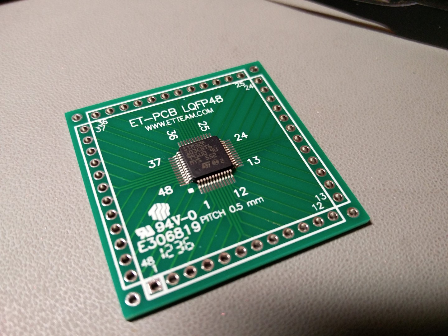
Enter the ST STM32F103C family of microcontrollers.
These little wonders are:
- Friggin’ fast. 32bit ARM architecture running at 72MHz.
- Very well equipped in the I/O department.. 2 x UARTs, 2 x SPI busses, 2 x I2C ports, etc.
- Easy to program using the familiar Arduino IDE, thanks to the work done by the wonderful people at www.stm32duino.com
- Dirt cheap. You can get an Arduino Nano – sized board for less than 3€ shipped.
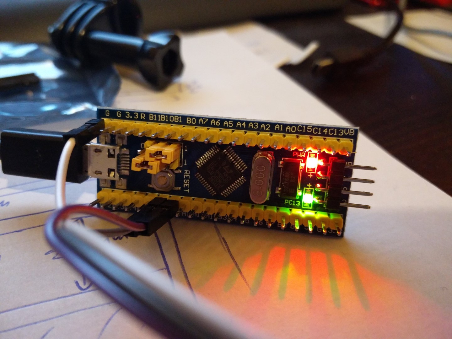
It’s pretty easy to get started using these microcontrollers. All you have to do is buy a tiny board from Ebay. You will also need a USB to Serial adapter that works with 3.3V voltage levels (you probably already have one of those lying around already..).
These tiny boards are known as “Blue Pills” or “Red Pills”, according to the colour of the PCB. There are other variations as well, but the red and blue variants are the most commonplace. They have relatively minor differences.
This is the pinout for either one of them:
To get started, you have to connect your USB to serial port adapter to the STM32’s RX1, TX1 and GND pins. RX from USB adapter goes to TX1 (PA9 pin) and TX goes to RX1 (PA10 pin).
To make the Arduino IDE compatible with these boards, you have to download the necessary files from here: https://github.com/rogerclarkmelbourne/Arduino_STM32
You then unzip the libary to C:\users\\Documents\Arduino\hardware\ or C:\Program Files (x86)\Arduino\hardware\
At the time of this posting, IDE 1.8.0 (latest available edition) is properly supported. You will also need to install support for the Arduino DUE or ZERO from the Boards Manager, otherwise you will get a “/bin/arm-none-eabi-g++: no such file or directory” error.
If everything went fine, you should see in your IDE a number of new available boards:
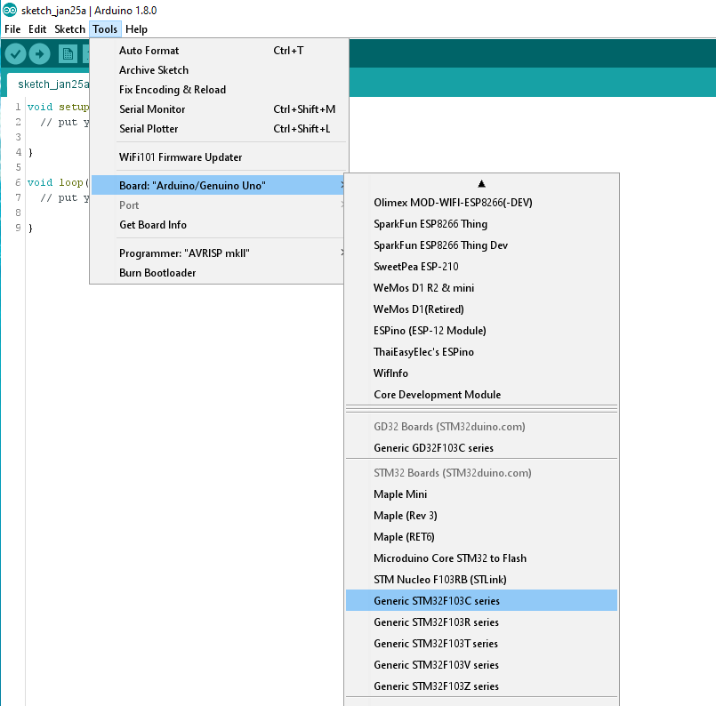
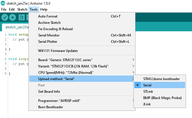
You select “Generic STM32F103C series”, the 128k variant, 72MHz speed, and Serial upload method:
You are now ready to try your first code upload.
The classic test is the Blink sketch:
// the setup function runs once when you press reset or power the board

void setup() {

  // initialize digital pin PC13 as an output.

  pinMode(PC13, OUTPUT);

}
// the loop function runs over and over again forever
void loop() {
digitalWrite(PC13, HIGH); // turn the LED on (HIGH is the voltage level)
delay(1000); // wait for a second
digitalWrite(PC13, LOW); // turn the LED off by making the voltage LOW
delay(1000); // wait for a second
}
In case of the STM32 uCs, the only necessary modification is changing the pin number of the LED to one compatible with the Blue (or Red) Pill (PC13).
Pin numbers for this family of uCs are not just numbers like they are for the Arduino boards (like 1,2,3….,A1,A2,…) but are named as they are described in the uC’s datasheet (PC13, PC14, etc.).
The procedure for uploading code is a little different than the one for the Arduinos. The STM32s come with 2 built-in bootloaders. One of them boots from system memory and the other from program memory. These different bootloaders are selected by changing the position of the BOOT0 jumper. You set it to 1 to boot from system memory or to 0 to boot from program memory.
To upload our code, we do the following:
- Set ‘BOOT0‘ to 1. This way we will boot from system memory which contains a UART to flash uploader.
- Press the RESET button.
- In the Arduino IDE, choose ‘Upload‘. On the board, the blue LED will start to flash.
After the upload is completed, our sketch will start. We should see the blinking LED.
If we want our uploaded sketch to boot automatically after the next power-on/reset, we need to set ‘BOOT0‘ back to 0 (so that on next powerup we will boot from program memory).
That’s pretty much it. Your next step should be to go to STM32duino’s forum and check out the libraries that have already been ported to the STM32duino environment.
Troubleshooting
If your sketch fails to compile, giving you a “/bin/arm-none-eabi-g++: no such file or directory” error, make sure that you have installed support for the Arduino DUE or ZERO from the Boards Manager.
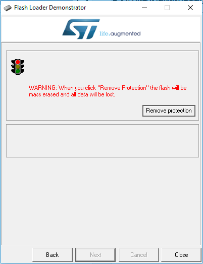
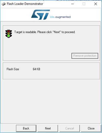
If you get an error on the IDE that it “Failed to erase memory”, that means that your STM32 chip is locked. No worries, all you have to do is go here and get ST’s Flash Loader Demonstrator utility. It will unlock the chip with minimum effort. Be sure to run it as Administrator in Windows.
Blue Pill reference: http://wiki.stm32duino.com/index.php?title=Blue_Pill