Buffalo Shield revision for B3SE

As I said, I will release a new revision of the Buffalo shield that will have better support for the B3SE.

Since that will probably take some time, in the meanwhile, this is what B3SE (or 32s or II) owners should do to their shields in order to support the B3SE:

IMG_6908_res_mod

The idea is to connect the photosensor side of one of the optoisolators directly to the IP_S header on the B3SE. In order to do that, you will have to cut one trace on the PCB and solder directly onto one of the optoisolator’s pins. That’s pretty much it.

On the new revision of the shield there will be a jumper where you have to cut the trace plus an extra pin so that you don’t have to solder onto the isolator’s pin.

TFT HiFiDuino v1.06

Here is version 1.06 of the code: TFT_HiFiDuino_v1.06b.zip (5080 downloads )
(11/12/2013: Update to v1.06b. Reason: minor bugfix)  (Note: As always, the code on this page may not be the current one, i.e. there may be a newer version available. The latest version is always up at the project’s official page.)

IMG_6903_fix_&_crop_res

IMG_6905_crop_res

The main difference is the support of Buffalo 3SE as well as an “always on” feature that bypasses the remote on/off sections of the code.

Here is the official change log:

– Compatible with Buffalo 3 and Buffalo 3 SE. Just comment out the relevant statement.
– Fixed “OS Filt” & “SR disp”.. They were not working correctly.
– Blue select boxes are gone.. they looked quite bad.
– Some other minor (mainly aesthetic) fixes..

A new revision of the shield is to follow (for improved B3SE compatibility).

Buffalo Shield v.1.1 for TFT HiFiDuino

Following my previous post on TFT HiFiDuino v.1.00, this is what you need to know in order to build my Buffalo Shield.

First of all, here are the DipTrace files (schematic & PCB): Buffalo Shield v.1.1 for TFT HiFiDuino (schematic & PCB) (9821 downloads )

And here is the relevant build & wire guide: Buffalo Shield v.1.1g for TFT HiFiDuino (documentation) (6909 downloads )

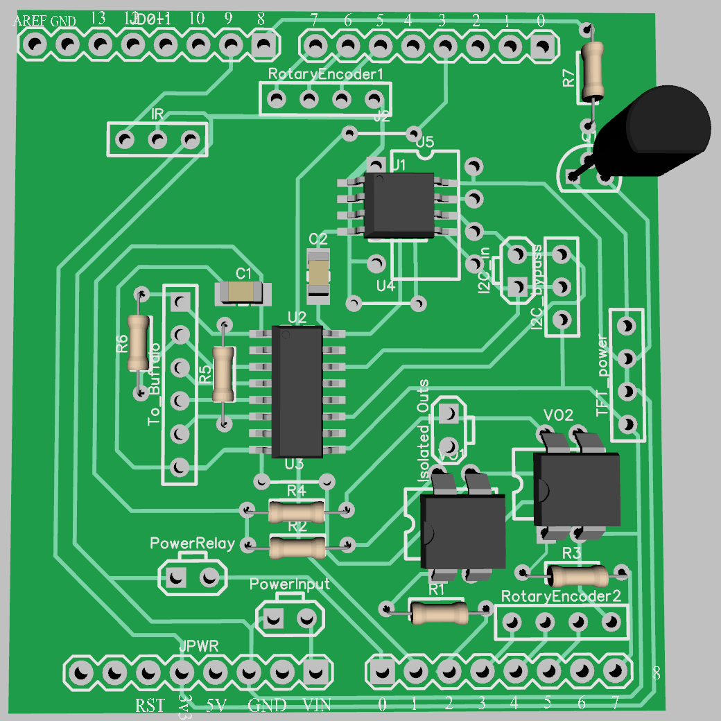
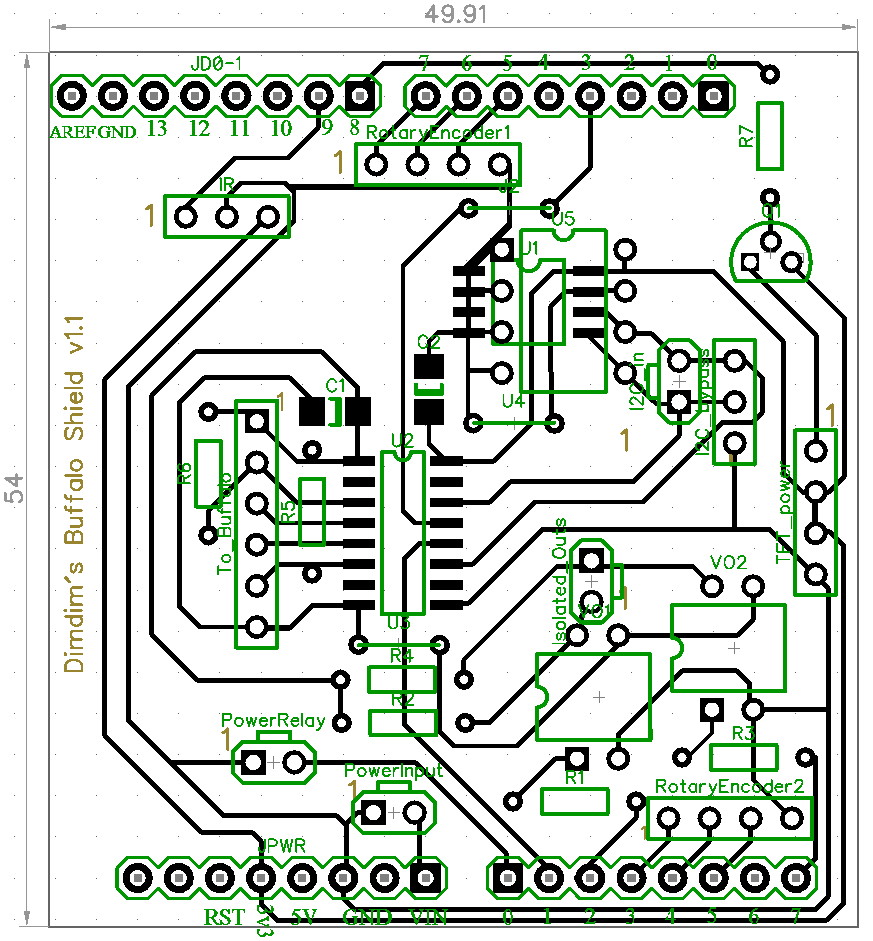
This is what DipTrace thinks the board ought to look like:
Arduino_Shield_1.1_Render_07_c

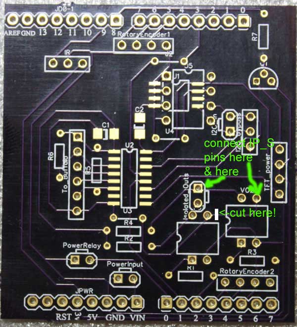
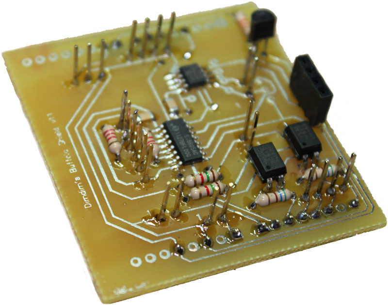
And this is what it actually looks like:
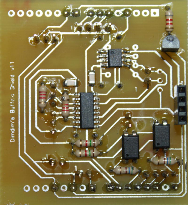
Arduino_Shield_v.1.1_1_800x872

Close enough..

This shield features:
– Galvanic isolation for the I2C signals as well as 2 digital outputs (Arduino -> Buffalo) and 1 digital input (Buffalo -> Arduino).
– EEPROM chip (24LC256) either in SMT or DIP footprint.
– Backlight control for the TFT through a PWM-controlled transistor.
– Headers for two rotary encoders.
– Output for power relay (for remote on/off).
– Header for IR receiver.

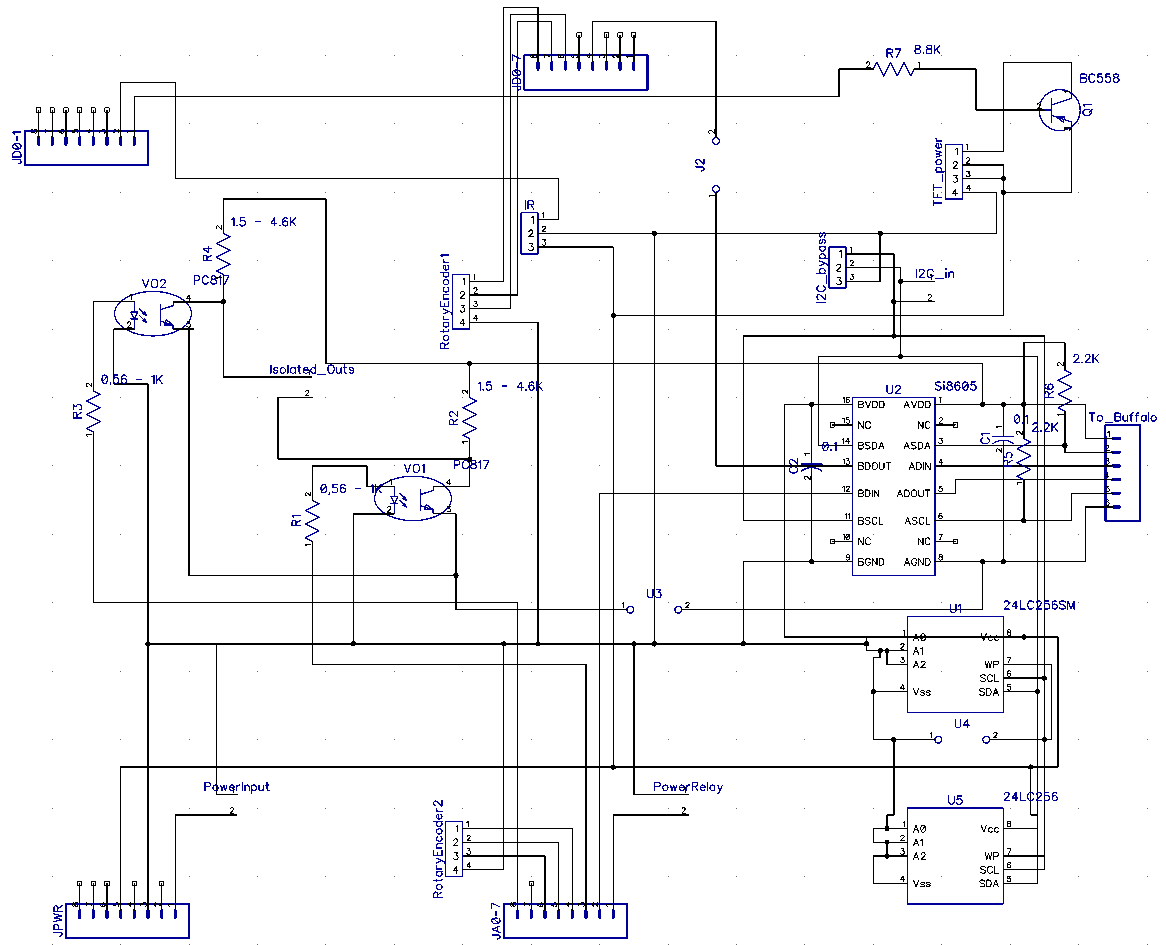
This is the schematic for the shield:
Arduino_Shield_Schematic-0.91

And this is the resulting PCB:
Arduino_Shield_PCB_v1.1b

This is a description of the various headers:

IR: Use a standard 38KHz IR Receiver Module, like the TSOP4838.
1: Signal (Pin 9)
2: GND
3: 3.3V

RotaryEncoder1: Use any simple rotary encoder.
1: Left pin (Pin 7)
2: Right pin (Pin 6)
3: Selector pin 1 (Pin 5)
4: Middle Pin & Selector pin 2 (GND)

RotaryEncoder2: Use any simple rotary encoder.
1: Left pin (Pin A3)
2: Right pin (Pin A4)
3: Selector pin 1 (Pin A3)
4: Middle Pin & Selector pin 2 (GND)

I2C_In:
1: SDA
2: SCL
(note: this is the I2C connection to the Arduino. SDA should be connected to pin 20 and SCL to pin 21)

I2C_Bypass:
1: GND
2: SDA
3: SCL
(use this if / when an isolator IC (U2) is not used to send the I2C signal to the Buffalo)

Isolated_Outs:
1: Out 1 (Pin A2)
2: Out 2 (Pin A7)

TFT_power:
1: TFT Backlight LED (dimmed by Pin 8)
2, 3: 3.3V (for TFT power & pin RD)
4: GND

PowerInput:
1: GND
2: Vin (8V-12V)
(connect here the power supply to the Arduino)

PowerRelay:
1: GND
2: 3.3V out (Pin A0) in case of Due, 5V in case of MEGA
(connect here the power relay that powers on the DAC)

To_Buffalo:
1: Buffalo Vcc (3.3V)
2: SDA
3: Sidecar Control (Pin 3)
4: Lock LED input (Pin A1)
5: SCL
6: Buffalo GND

TFT HiFiDuino: Phase 1 complete!

It took quite a bit longer than I had expected but I am happy to report that Phase 1 of the TFT HiFiDuino project is complete.

v.1.00_screenshot_1_800x471

The objectives of Phase 1 were the following:
– Have full control over the parameters of the ES9018 chip. Essentially be able to write to all of the useful registers.
– Be able to have full IR remote control functionality.
– Be compatible with both the MEGA as well as the Due Arduino boards.
– Be able to switch between all 8 of the supported s/pdif inputs, as well as between I2S sources (USB in my case).
– Develop an Arduino shield that would simplify the wiring of the thing as much as possible as well as provide galvanic isolation between the Arduino and the DAC board.

All of these objectives have been accomplished, so here is v.1.00 of the code: TFT HiFiDuino v.1.00 (4796 downloads ) (Update: there is a new version available! Click here for the latest version.)

If you happen to come across a bug, please let me know by posting a comment below.
Feel free to use it whichever way you see fit, modify it, redistribute it, whatever, as long as you do not profit from it.

Requirements:
UTFT Library
– Fonts (included in the ZIP)

I will also make available the schematics & PCB for the shield, although it is not really necessary for operation of the controller.
Here is a preview:
Arduino_Shield_v.1.1_1_800x872

Arduino_Shield_v.1.1_2_800x630