TFT HiFiDuino v2.01 + video

As is usually the case, a few bugs crept into the v2 release. So, here is v2.01: TFT_HiFiDuino_v2.xx (11140 downloads ) (Note: As always, the code on this page may not be the current one, i.e. there may be a newer version available. The latest version is always up at the project’s official page.)

Also, here is a video of the code in action:

TFT HiFiDuino v2!

It’s official: Version 2 of the TFT HiFiDuino controller is complete!

There is a number of changes, thus the new version:

  • New minimal display mode as default. Goes into full display when changes are to be made to parameters.
  • Full graphics support in the minimal display.
  • New proportional fonts (TrueType).
  • New IR code. Now supports a much larger range of remote manufacturers.
  • Support of MCP23008 IC to control misc devices.
  • New option to set 0db as default (power-on) volume for connection to a preamp.

The code is (and will remain) compatible with my current shield. (Hint: shield v2 is also coming up!)

New requirements:

Plus the good old UTFT library.

I am including the necessary fonts and bitmaps in the ZIP. The fonts should go into your UTFT & UTFT_DLB directories, usually found in the Windows user’s Documents folders (for example, here: c:\Users\<user name>\Documents\Arduino\libraries\UTFT_DLB\).

The bitmaps should go into your sketch’s folder.

I have included in several places in the code SerialUSB output for debugging purposes. It is commented out in this release for performance purposes. However, it is very easy to re-enable for either debugging or viewing of the IR codes sent to the Arduino. You may use these IR codes to customize the code to support your remote by changing the relevant #define statements in the Remote control definitions section.

Due to code size and performance requirements I’m afraid that from v2 onwards TFT HiFiDuino will only be compatible with the Arduino Due. Sorry, it’s the price to pay for nice graphics. Thankfully, it’s a pretty low price. 😛

You may download it here: TFT_HiFiDuino_v2.xx (11140 downloads ) (Note: As always, the code on this page may not be the current one, i.e. there may be a newer version available. The latest version is always up at the project’s official page.)

I will soon update the code’s official page to v2.

IMG_8600_resize

Laying out a display is hard work, Part 2

A couple of weeks back I wrote that I was working on the next version of the TFT HiFiDuino code and that I was struggling with its new aesthetic.

I was considering something resembling this: 2014-12-14 21.50.50_resize

But, I did warn you that the final version would probably look nothing like this. I was right.

Two weeks have passed since then and I am very close to a v2 release. The aesthetics are 99% complete and I am just ironing out a few bugs.

This is the final look: IMG_8570_crop_res IMG_8567_crop_res

Stay tuned.. v2 will be out before the end of 2014!

Laying out a display is hard work..

..especially if you have almost no technical constraints in what you can implement. It’s only pixels, after all.

Yes, I am talking about a new version of the TFT HiFiDuino code with a new look and feel.

2014-12-14 21.50.50_resize

This of course is very very preliminary, and chances are the final version will look almost nothing like it, but still it will give you an idea as to where I’m going with the design.

The new version will have a minimal main display and only show the good stuff when an adjustment is to be made. The underlying code is nearly complete, but I’m struggling with the aesthetics of the thing.

But in any case, it won’t be long now. 🙂

The TFT HiFiDuino Chronicles: 21 months in the making..

Since the very beginning of my Buffalo III project, I had decided that I would use an Arduino to perform all of the control functions (source selection, volume control, setting of parameters, etc.).

At first I thought that I would just do basic interfacing, that is control the Buffalo by interfacing with the built-in controller. After taking a closer look at HiFiDuino’s work it became apparent to me that direct I2C interfacing was the way to go. Since I wanted to use a better display than the one used in HiFiDuino, I shopped around for a nice color TFT screen. I bought one from Adafruit and got busy. After a few hours of figuring stuff out and coding I got to this point:

IMG_5249_resize

IMG_5251_resize

The date was March 3, 2012.

On that day I started a thread at avclub.gr announcing my Buffalo controller.

At this point since a number of people had expressed interest in the project I thought it a good idea to look for a less expensive TFT, sourced through Ebay rather than Adafruit. $50 for a 2.8″ TFT is indeed a bit steep. I came across this little gem:

TFT280

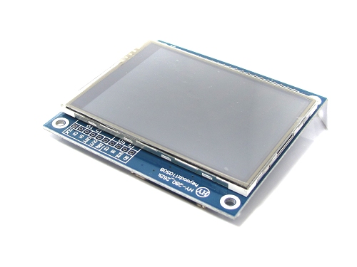
At $20 the price was right, but it was not compatible with Adafruit’s display library so I searched for a compatible library. I came across Harl Henning’s UTFT library which appeared to be exactly what I needed. It was compatible with a large number of TFTs, including the ones that I had on hand. I took care of some signalling issues (the new TFT needed 3.3V signalling but the Arduino Mega is 5V) and proceeded to adapting the code to the UTFT library.
At that time I discovered that HiFiDuino had also just discovered the UTFT library and was planning to use it as well. That was a nice surprise. He had got a hold of a 3.2″ 400×240 TFT which was also available on Ebay so I also ordered one and decided to standardize on that. The date was April 15, 2012. It was Easter.

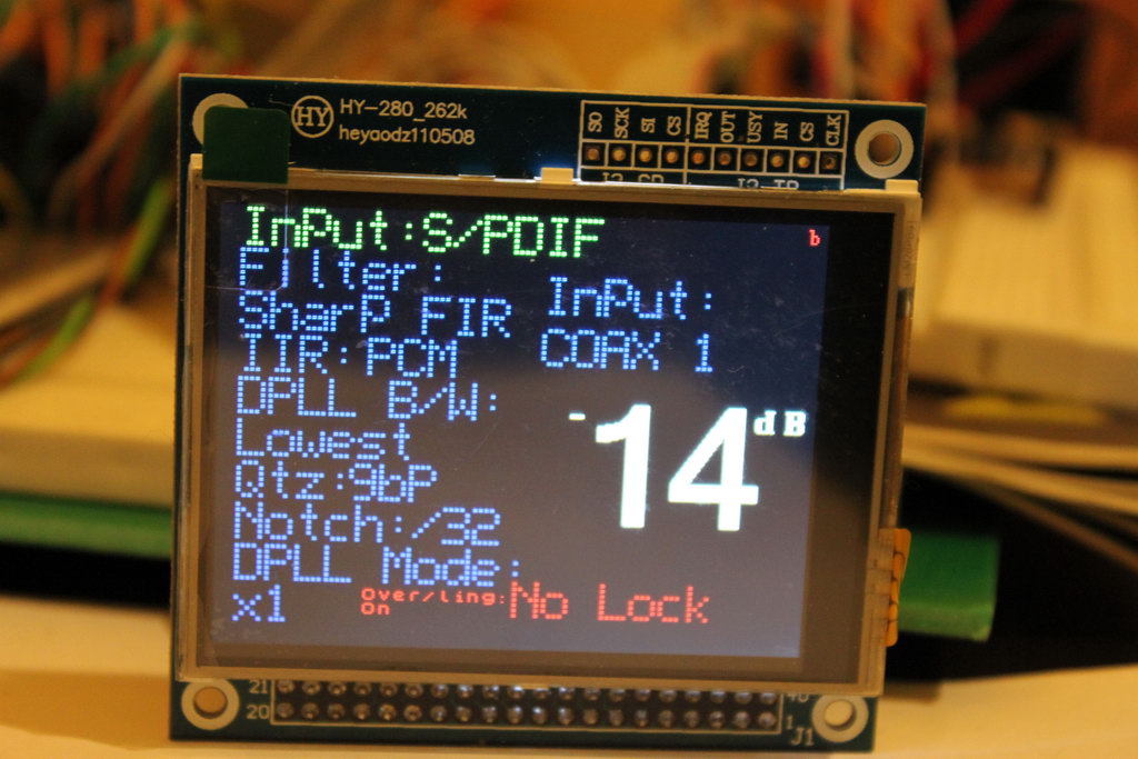
While waiting for the 3.2″ TFT, I continued my work on adapting the code to the UTFT library. After having tried various fonts, including making a few of my own, I settled on these:

IMG_5388_resize

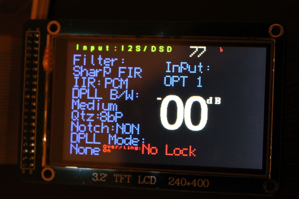
By the end of April the 3.2″ TFT had arrived and I confirmed that it worked. This is what it looked like with no code changes (they would be necessary since I wanted to make use of the total screen real estate).

IMG_5410_resize

At that time the weather got pretty warm so I froze all DIY activities for the summer. The DAC was not really finished but it was functional at the time so I was in no rush.
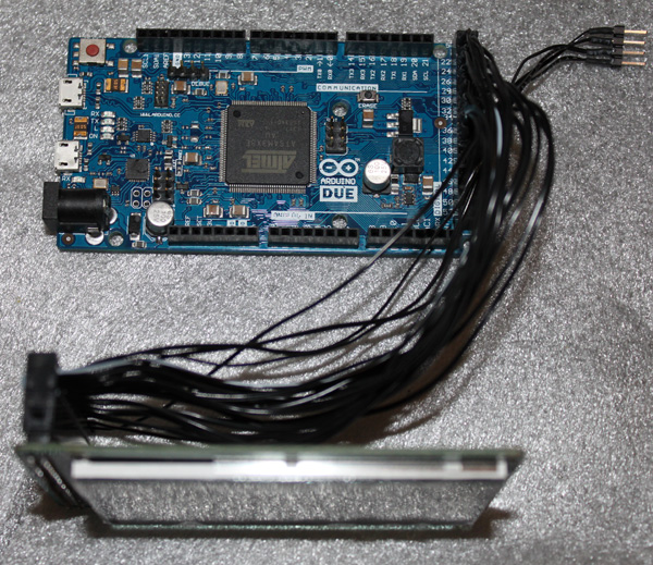
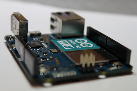
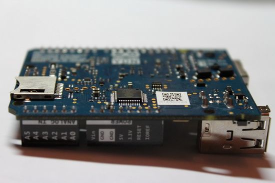
It was not until late November that I resumed the project. The new Arduino Due was becoming available in stores and I was anxious to see whether the improvement in speed would actually translate to real world improvement in Buffalo response times. Before the end of November I had received the Due.

533545_4591777745791_109805203_n

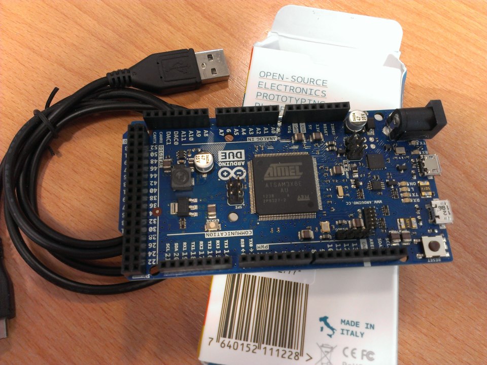
Since the Due was built using 3.3V logic, it was now easier to interface with the 3.2″ TFT and also the I2C lines would no longer need level change to the 3.3V that the Buffalo liked.

At this time I realized that there where 2 obstacles that I had to overcome:

1) The UTFT library was not compatible with the Due.
2) The Due did not have any on-board EEPROM so I could not save my code settings.

The first problem was solved 10 days later when a couple of lovely people at arduino.cc took it upon themselves to make changes to the UTFT library so as to support the Due. The hacked version of the library worked like a charm. I was very impressed with how little time it took these guys to adapt the library.
The second problem I tackled on my own, by adding a 24LC256 EEPROM chip to the design and adapting the code.

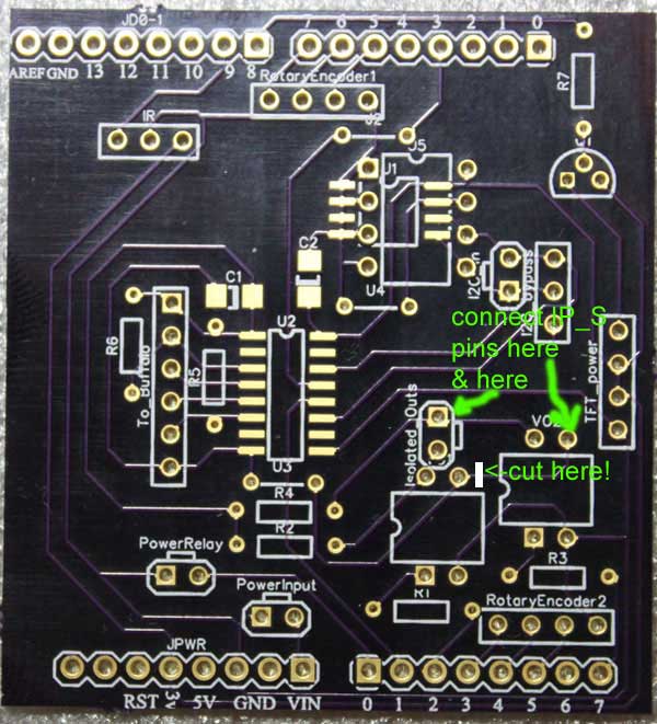
This is when I first came up with the idea of designing a custom shield for the controller. It would accommodate the 24LC256 as well as the necessary parts for electrical isolation between the Arduino and the Buffalo.

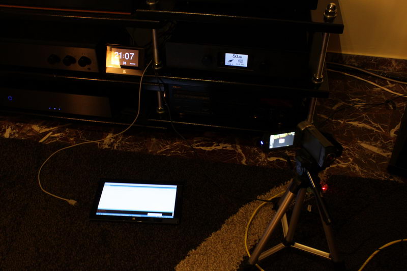
By mid January I had made sure that my code ran equally well on the Due as well as on the Mega, so I thought that I would produce a short video demonstrating the difference in processing power. That video has since gotten more than 2.000 views per month. Here it is:

By the end of February I had proceeded with polishing the code and had a rough draft of the shield.

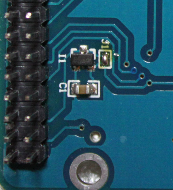
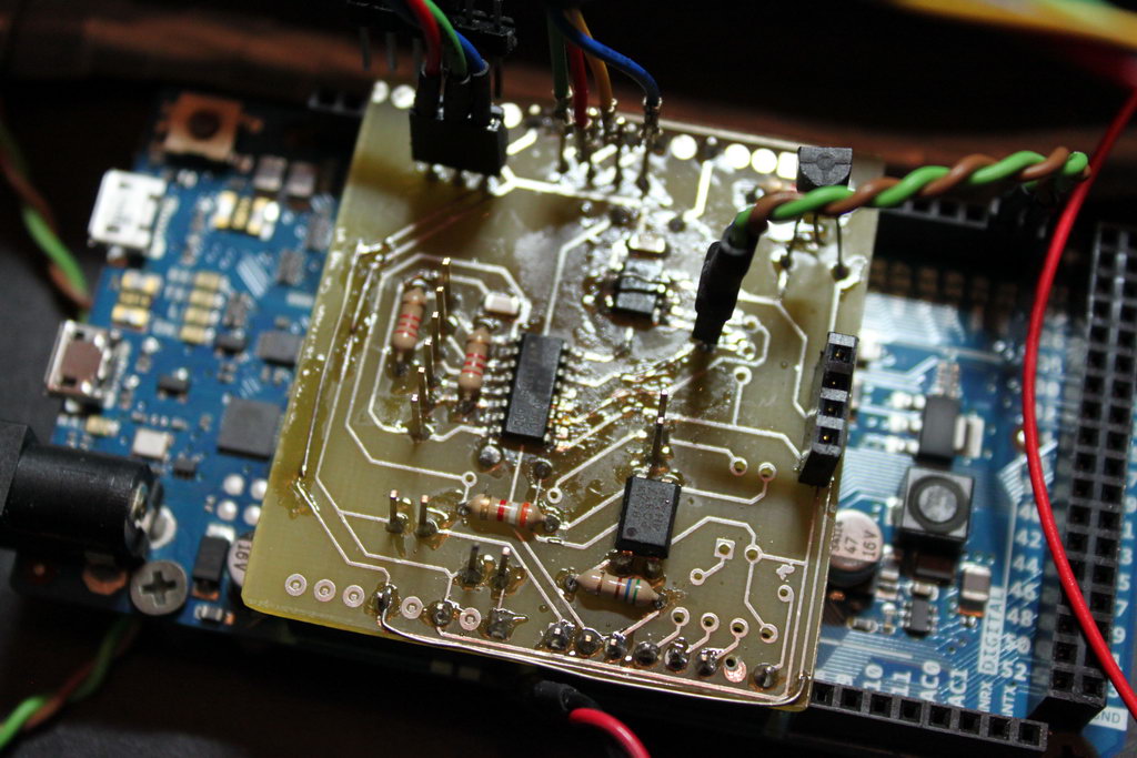
About a month later I had a (nearly) working prototype of my new shield:

IMG_6274_resize

At that time, once again, the weather got too good for DIY so I suspended the project until September.

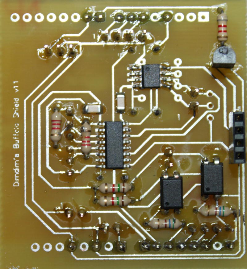
While I was on summer leave I got a little bored so I resumed the project. It moved along pretty fast, and soon I had a final version of the shield:

Arduino_Shield_v.1.1_1_800x872

..and a v.1.00 of the code:

v.1.00_screenshot_1_800x471

I proceeded to release the actual code and schematics for the shield on September 3 & 7 respectively, as well as some basic instructions on building it.

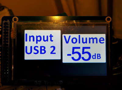
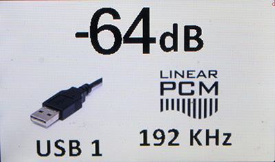
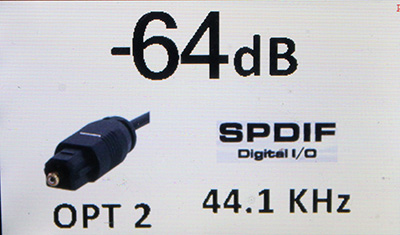
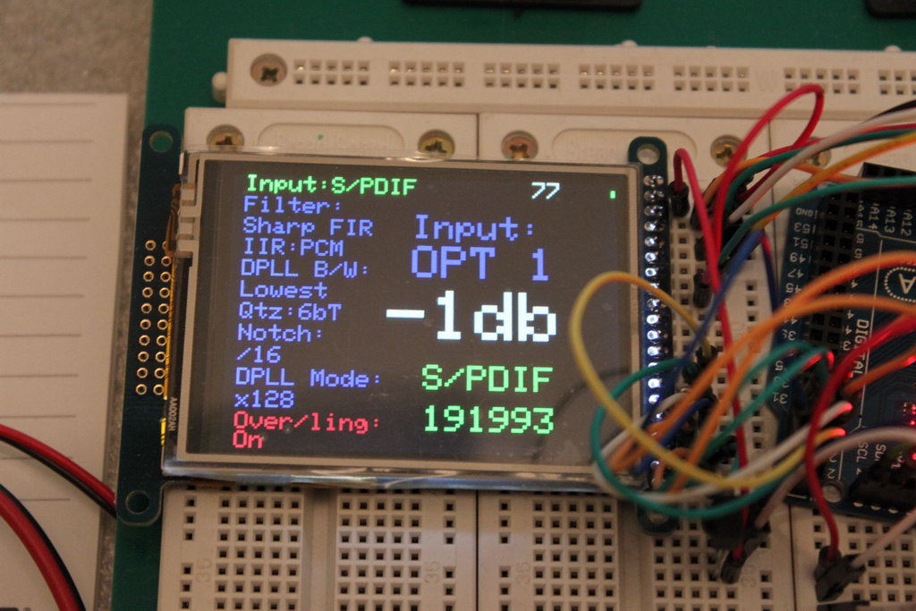
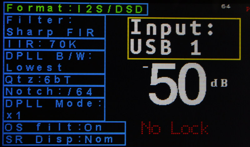
The next step was to make the code more Buffalo-III SE friendly, since most people buying Buffalos were going for the SE. I had one last request: to give the option of always-on, in other word to make it possible to bypass the “on/off” portion of the code. That was pretty easy to implement. At last, I made a few aesthetic changes. The end result was v1.06b, released at December 11, and it looked like this:

IMG_6903_fix_&_crop_res IMG_6905_crop_res

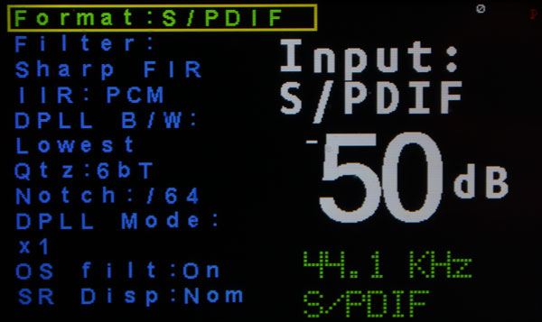
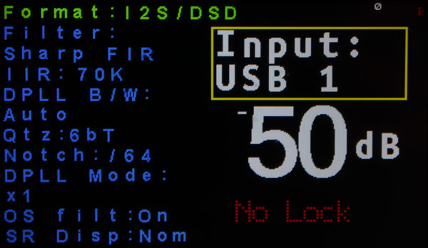
(the above screens are from the Buffalo-III SE version of the code)

And that’s it so far.

Buffalo Shield revision for B3SE

As I said, I will release a new revision of the Buffalo shield that will have better support for the B3SE.

Since that will probably take some time, in the meanwhile, this is what B3SE (or 32s or II) owners should do to their shields in order to support the B3SE:

IMG_6908_res_mod

The idea is to connect the photosensor side of one of the optoisolators directly to the IP_S header on the B3SE. In order to do that, you will have to cut one trace on the PCB and solder directly onto one of the optoisolator’s pins. That’s pretty much it.

On the new revision of the shield there will be a jumper where you have to cut the trace plus an extra pin so that you don’t have to solder onto the isolator’s pin.

TFT HiFiDuino v1.06

Here is version 1.06 of the code: TFT_HiFiDuino_v1.06b.zip (5108 downloads )
(11/12/2013: Update to v1.06b. Reason: minor bugfix)  (Note: As always, the code on this page may not be the current one, i.e. there may be a newer version available. The latest version is always up at the project’s official page.)

IMG_6903_fix_&_crop_res

IMG_6905_crop_res

The main difference is the support of Buffalo 3SE as well as an “always on” feature that bypasses the remote on/off sections of the code.

Here is the official change log:

– Compatible with Buffalo 3 and Buffalo 3 SE. Just comment out the relevant statement.
– Fixed “OS Filt” & “SR disp”.. They were not working correctly.
– Blue select boxes are gone.. they looked quite bad.
– Some other minor (mainly aesthetic) fixes..

A new revision of the shield is to follow (for improved B3SE compatibility).

3.2″ TFT connection to Arduino Due (UPDATE!!)

In this post I talked about the 3.2″ 240×400 TFT and how it can be connected to a MEGA or Due.

Since then I realised that I might have made things a bit more difficult than they need to be, so I decided to give it another go, this time making a (relatively) foolproof guide. So here goes.

The finished assembly should look something like this:

finished_cable_1

What you need:
– An old 40 pin IDE cable. If you can’t get your hands on a ready-made IDE cable, you will need to find some 40 pin ribbon cable and a 40 pin connector (you can find it as “IDC40 IDE FEMALE CONNECTOR”) so you can roll your own. You will also need a small vise to press the connector.
– A 2×13 (or larger) pin header.
– A 1×4 (or larger) pin header.
– Some heat-shrink tubing.
– A soldering iron, etc.

We will be connecting only the wires necessary for operating the TFT as a display, so no SD card reader or touchscreen. You should keep that in mind.

Also, this cable only works with the Due, since it uses 3.3V logic. In order for it to work with the MEGA, 10K resistors should be connected in series with all the signal cables (except of course for the Vcc, LED-A and GND lines).

Let’s begin.

You start by cutting your IDE cable to the necessary length (or in case you’re making your cable from scratch, using as much ribbon cable as you need). The connectors on most IDE cables have one of the pin holes blocked, so you should use a small drill to open it up.

The pin numbering always starts from the red wire, so it goes like this:

IDC40_pin_numbering

I prefer to cut off the unnecessary wires. This way there is less clutter, plus it is harder to get confused. Once the unnecessary wires have been cut off, we are left with this:

IDC40_pin_numbering_2

So this is one side of the cable. On the other side we will solder on to these:

pin_headers_1

They are two pin headers. The 1×4 one is for LED backlight, Vcc power, RD and ground respectively. That corresponds to these pins:

pin_headers_3

Finally, we have the 2×11 pin header. We need to make these connections:

pin_headers_2

The numbers are obviously pin numbers that correspond to the 40-pin ribbon cable. It should be pretty easy to get them right.

You should use heat-shrink tubing in order to insulate the connections, as well as improve the mechanical properties of the connections.

You will notice that the header is missing two pins (on the far right). That is done on purpose, to make it easier to align with the Due’s connector:

2x11_on_Due

And here is the finished cable, connected to the TFT as well as the Due. Note that it’s up to you to connect the 1×4 header whichever way you can.

Due_and_TFT

Notice that the ribbon cable is coming out of the IDC connector and going to the right, and not to the left. Should you connect it the wrong way, it is very likely that the TFT will be damaged, so be carefull!

You should also solder/jumper these pads (J1) on the back of the TFT:

TFT_J1

We have to do this since we are already powering the TFT with 3.3V. This way the local regulator will be bypassed.

That’s it! Good luck..

Arduino Yún, Part 2

OK, I have had my Yún for 3 days now, so let’s get started.

First of all, pictures:

Yun_top_1

Yun_top_2

Yun_top_3

The heart of the Arduino core: the Atmel MEGA32U4 microcontroller. 32KB of Flash memory, 2,5KB of SRAM and 1KB of EEPROM, the usual I/O, essentially a Leonardo. Pretty classic stuff.
MEGA32U4

What is not visible in the pictures, is this:
Atheros_AR9331_2This is the Atheros AR9331 processor. It runs at 400MHz, has 16MB of Flash, 64MB of RAM and runs Linino, a Linux distribution based on OpenWRT.

Yun_bottom_1

Yun_bottom_2

Yun_bottom_3

Now, with 3 different reset switches! From left to right, for the Yun (Linux), the WiFi and the 32U4 (Arduino).
Reset_Buttons

I was wandering how fast “upload a sketch over WiFi” was, so I made a little video comparing it to the classic “upload over USB”: