The Texas Instruments PCM4222 Evaluation Board

I had been looking for a good ADC board for lab use as a measurement device.

At first I considered making my own, using something like the TI PCM4222 ADC chip, due to its excellent performance, good availability and relative ease of build.

But then I got lazy and purchased the PCM4222 EVM instead:
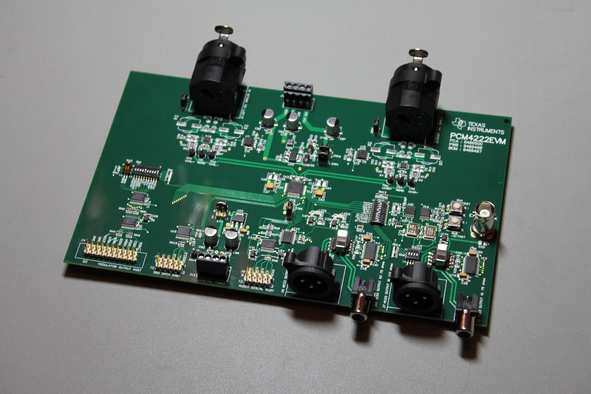
PCM4222EVM top

It is a 4-layer, well designed and implemented board.

Besides the necessary 2 clocks, it has a full set of digital outputs:
– Dual AES3 compatible outputs (both coaxial at 75Ω and XLR at 110Ω)
– I2S
– DSD
– Raw, directly from the modulators

Its analog inputs are balanced and very low noise.

Make no mistake, this is an evaluation module. As such, there are no mounting holes. Just four rubber “feet”:
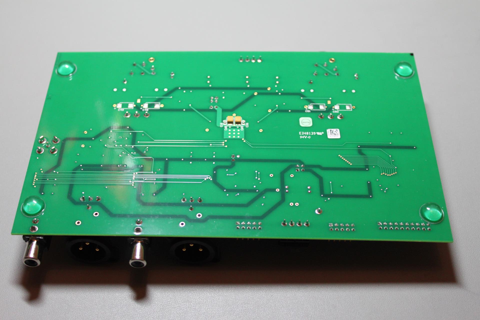
PCM4222EVM bottom

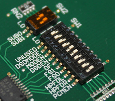
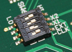
Since I was in a hurry to get it to work, I set it up for operation with the least amount of power supplies (+/-15VDC and +5VDC) and set the DIP switches for I2S operation at 24bit and 96KHz.

I wanted to use one of its built-in AES3 outputs, but my sound card only had consumer level s/pdif inputs. After a short Google search, this came up: http://www.rane.com/note149.html

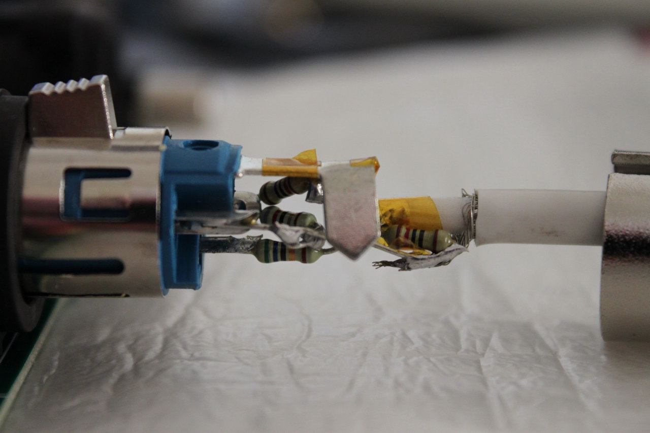
In other words, I had to make a 75Ω cable, with an XLR at one end, an RCA plug at the other and this circuit embedded in the XLR plug:
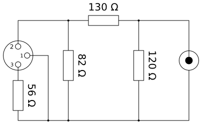
AES3_to_SPDIF

Surprisingly enough, it fit.

IMG_9400_resize

I hooked it up to the ‘scope to see if everything looked OK, and after being satisfied with what I saw I hooked it up to my X-Meridian’s coax s/pdif input. The sound mixer in Windows showed a full level signal coming out of it but it was heavily distorted. What was going on?

While troubleshooting, I tried the serial output port by connecting it to a WM8804 board that I had lying around. Sure enough, I got proper undistorted s/pdif output, so the PCM4222 was working as it should. So the problem had to be in the AES3 drivers.

After some more Googling I came across a post in some forum by someone who had a similar problem with me. He said that for some reason he had to set the ADC’s output to Left Justified (instead of I2S) in order to get the AES3 transmitters to output a proper signal. I made the necessary changes to the microswitches and lo and behold, it worked!

This is the configuration that I ended up with:
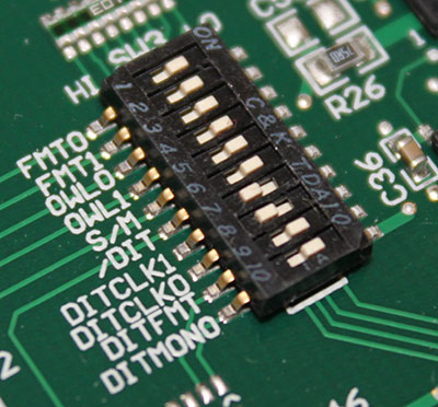
config_2496_LJ_2

config_2496_LJ_1

config_2496_LJ_3

Next up is a proper input stage, since the ADC has balanced inputs but most of my equipment-under-test is single ended.
Soekris R-2R: Sound impressions with Salas BiB PS & alpha20 line stage

A couple of days ago I took my DAM and headed out to a good friend of mine to do some listening tests.

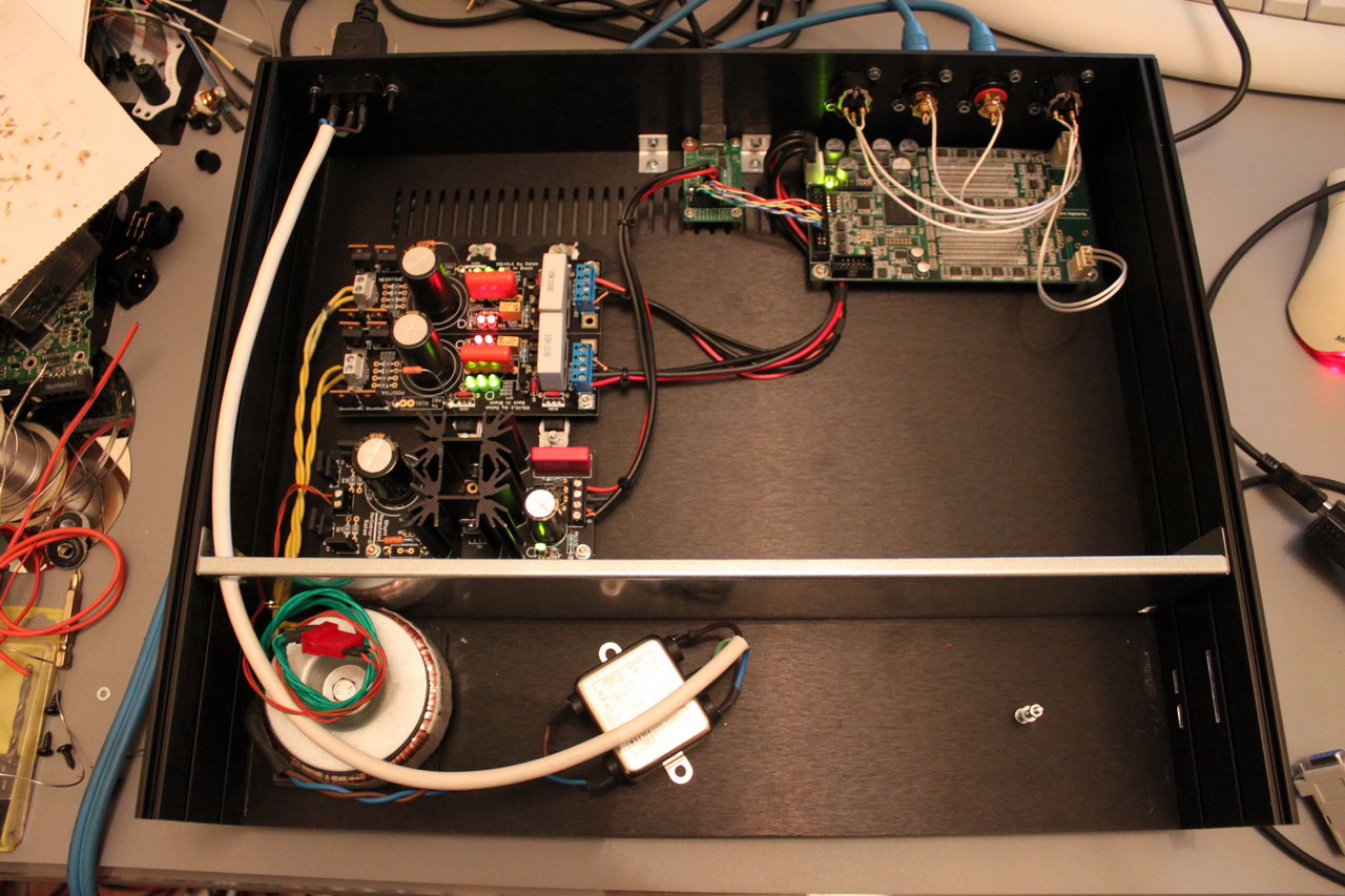
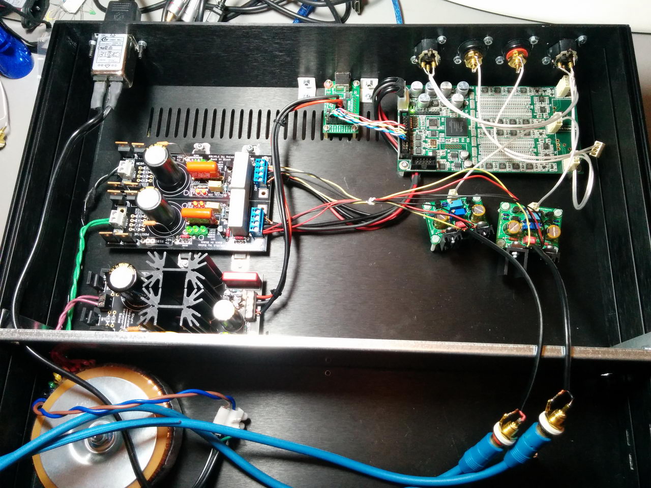
My DAM at the moment is powered by a Salas BiB at 12VDC. It has a DIYINHK XMOS based USB to I2S interface powered by a Salas Reflektor-D at 3.3VDC. The same power supply powers the isolated side of the DAM.

IMG_9263_resize(note that this picture is a bit old. I have since swapped the transformer for the one shown in the next picture plus I have used an IEC with a built-in filter)

The first objective was to assess the importance of a good DC power supply instead of a plain transformer. In order to do that I took with me an extra 50VA toroidal with 2 x 7V windings.

My friend’s system consists of Magnepan speakers, a DIY fet-based preamp and DIY power amp (solid state, 60KG monster). It is widely regarded as a very revealing and non-forgiving system. Any change in any of its components (or a component withing the components) is clearly heard.

The DAM was connected to the preamp through its unbuffered outputs.

We gave the system some time to warm up (it was probably a couple of hours) and then sat down to listen. We started with the DAM as it was, with the Salas BiB. We then unplugged the Salas and hooked up the plain transformer.

The change was immediately obvious. The sound thinned, it became more harsh in the high end. It also lost resolution and detail. Going back to the BiB made all the good qualities come back.

Thus, I can definitely recommend a proper DC power supply for the DAM. I cannot say whether it was the Salas that did the work or that any DC power supply would do the same, but the improvement was definitely there. Note that I have the BoM for the Salas BiB I built in the Soekris’ page.

The second objective was to assess the difference that could be made by using a “proper” output stage after the unbuffered outputs.

So I built a pair of AMB alpha20 line amplifiers. I set their gain to 2 and powered them temporarily by the same Salas BiB that powers the Soekris.

2015-03-27 01.36.57_resize

Note that my DAM outputs roughly 1V RMS at its output @ 0db since I’m using a filter that includes attenuation at FIR2 (I can’t really remember which one it is though..). This meant that the alpha20 brought its output to a nice 2V RMS.

Going back and forth between using the alpha20 and just the unbuffered outputs, the conclusion was that the alpha20 removed a small amount of the “magic” of the DAM while not really helping in anything besides output volume. I was hoping that it would help improve the dynamics of the DAM – its Achilles’ heel IMHO. In my friend’s system the DAM sounds “flat” compared to his other sources (a heavily modified Sony 50ES cdp, a Buffalo 3 DAC, and an Aune S16). However, this “flatness” is not particularly obvious in other more forgiving systems.

So, my assessment of the DAM so far is as such: It has great detail, exceptional mid-range, proper bass, it is a little soft on the highs, but its main problem is the dynamics. It can sound a bit “flat”, with this “quality” either accentuated or minimized, depending on the rest on the system.

If there was a way to improve its dynamics, to make it more “aggressive”, it would be a stellar performer (with a proper DC power supply of course). As is, it is just great VFM.

Soekris R-2R: Interfacing to an Arduino

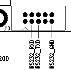
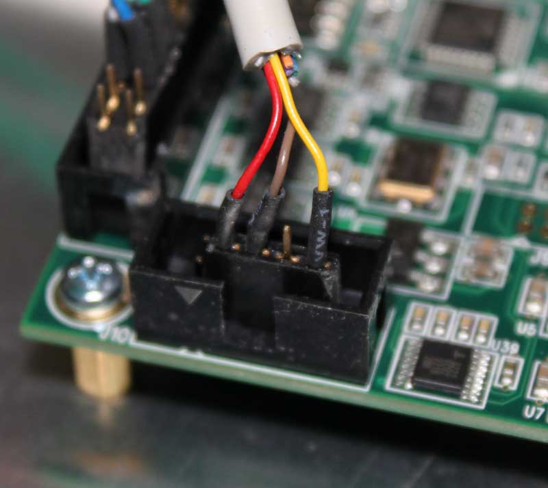
The Soekris dam1021 has a serial port (J10).J10-serial
This serial port serves a number of purposes:

1) It is used for uploading firmware updates via the uManager prompt.
2) It is used for uploading filter values via a software utility (not yet released).
3) Outputting info on currently selected Input, Sampling Rate and Volume level.
4) Controlling things by receiving commands. Up to now, we can select Input and change the Volume. More commands might be added in the future (or already exist, but are not yet documented by Soren).

In order to do all those things, one has to interface to this serial port. In this post I detailed how to interface a computer to this port (so as to perform a firmware upgrade). Now it is time to do the same for a microcontroller, say an Arduino.

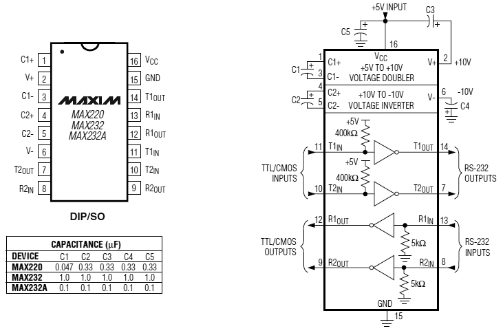
The problem is, microcontrollers use different voltage levels compared to the “classic” RS-232 serial protocol. In order to make these different things talk to each other, we need to use what is called an “RS-232 Receiver / Transmitter” IC. Such ICs are pretty commonplace, since they are found inside of most devices that come with RS-232 interfaces. The “classic” IC that is used is the Maxim MAX232. It is very low-cost but it is also an old design, requiring 5V (instead of 3.3) and 5 x 1μF capacitors. There is a much newer version of the chip, the MAX3232, operating with a voltage between 3V and 5V and requiring much smaller caps (0.1μF), but it is not as widely available as the MAX232. Since I was in a hurry to get things up and running, I chose what I could find locally in stock: a MAX232.

MAX232

This meant that I had to power it with 5V and use 1μF tantalum or ceramic capacitors, but what the heck. I was in a hurry.

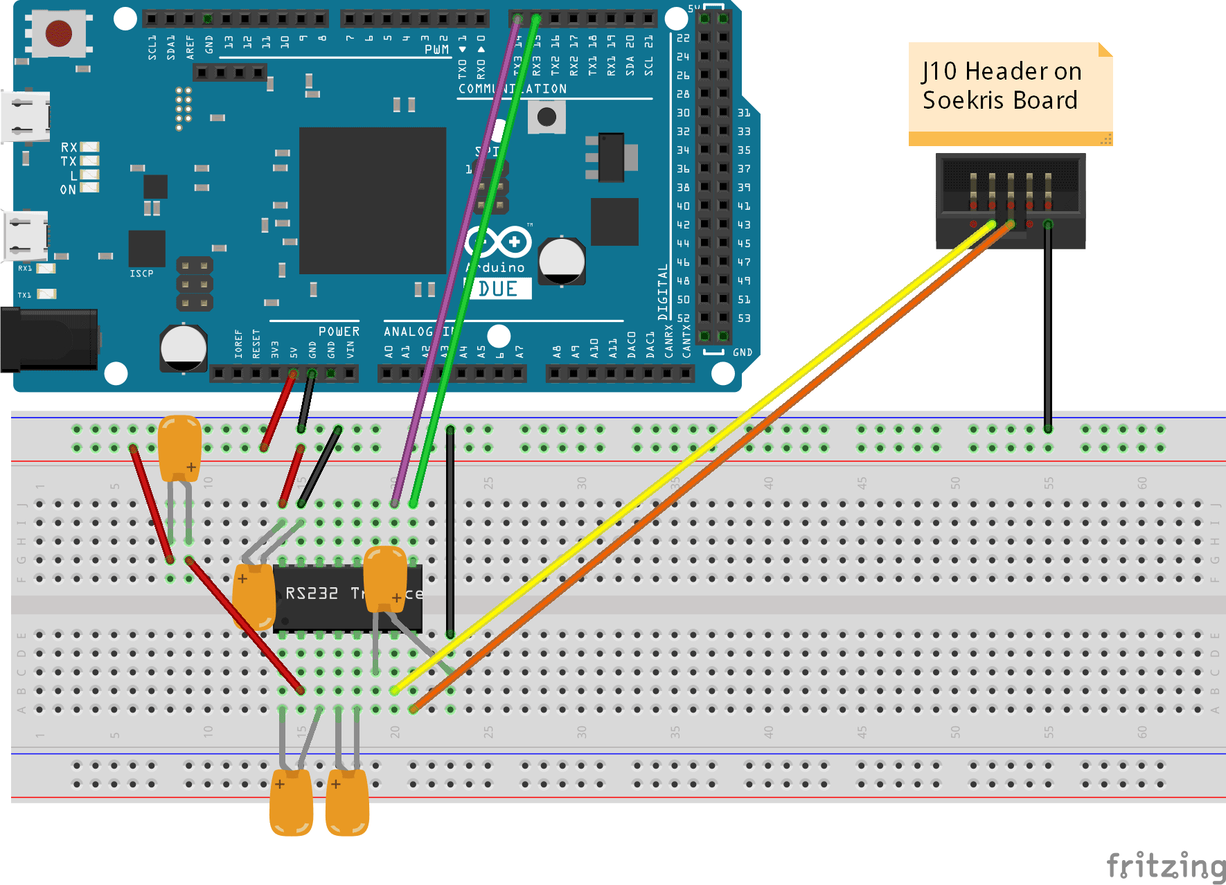
After reading the MAX323’s data sheet I ended up with this:

RS-232-interface_v2_bb
(click on the picture for a higher resolution version)

You will notice that I am using Serial3 of the DUE to talk to the DAM DAC. Any serial port could be used, but I chose Serial3 because it was practical – it will be easy to route these specific pins on the shield that I am designing.

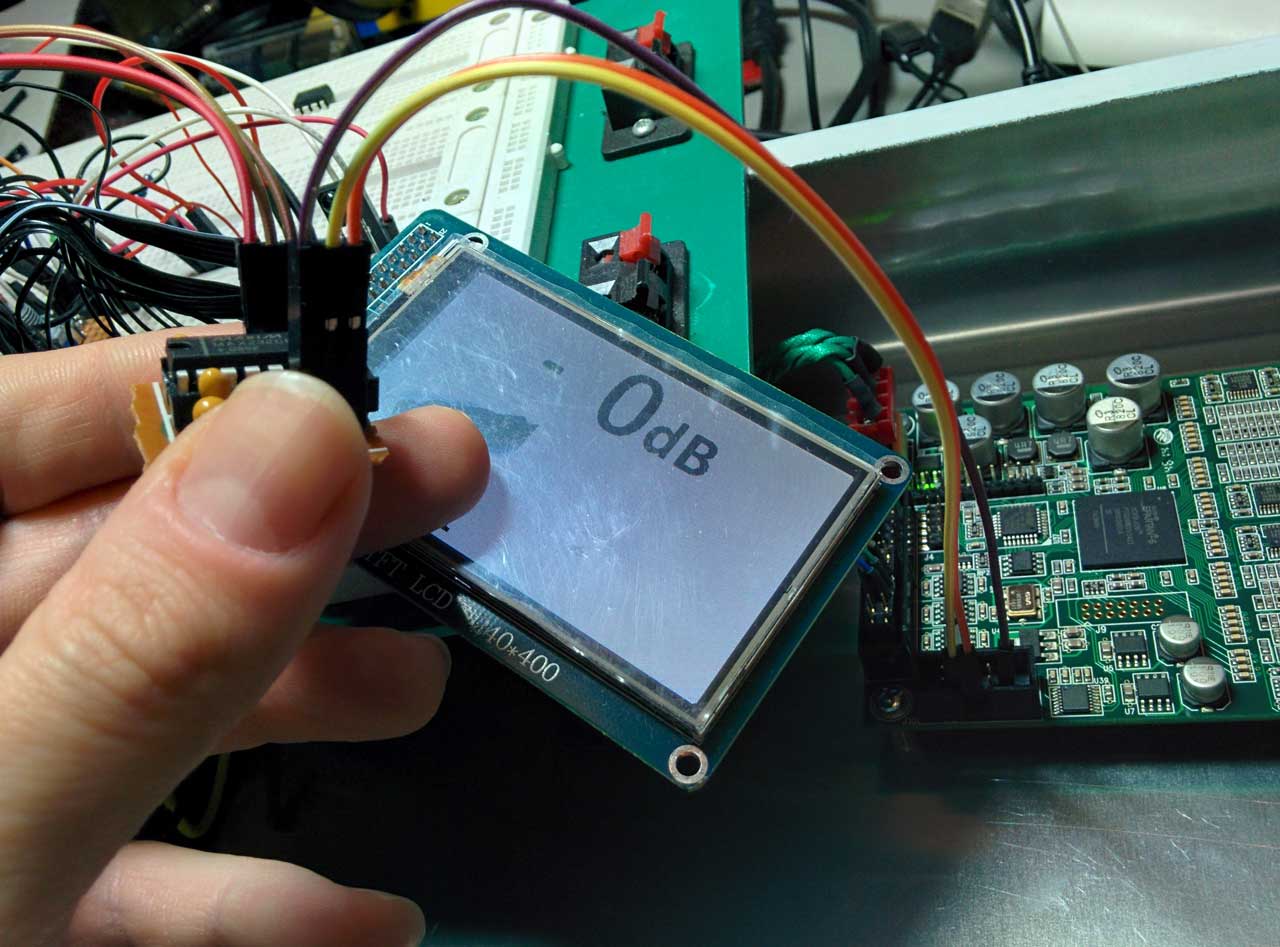
Once I verified that the above circuit worked, I built it on perfboard to keep handy:

MAX232_interface

The above circuit works in general but has some trouble with the DAM DAC. It works just fine upon power up but at some point loses communication with the DAC. The only way to restore communication is to power cycle the DAC. I am not sure what the problem is, but I suspect that it has to do with the power management features of the ICL3221 chip used on the DAM. I have ordered an ICL3221 to use in place of the MAX232, in hope that everything will work fine when I use this (at least in theory) fully compatible IC.

Stay tuned.

Soekris R-2R: Firmware upgrade

The DAM1021 originally came with FPGA firmware 0.8. Since then Soren has released a new version of the firmware, Rev 0.9.

J10-serial
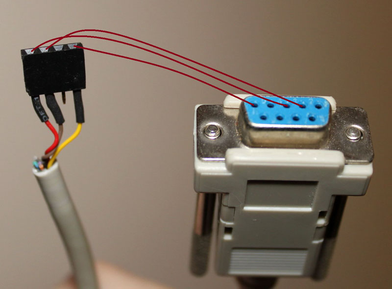
In order to upload it to the DAC one must connect the DAC to a computer using either a “classic” serial port, like the one found at the back of older computers, or a USB to Serial adapter. Then a cable must be made connecting three pins of the DB9 connector to the connector J10 on the DAC board.

These pictures illustrate the connections that are needed:

RS-232_to_Soekris

RS-232_to_Soekris_2

You use your new cable to connect the DAM to your computer’s serial port (or USB-to-serial adapter). You do not power on the DAM DAC just yet.

Once you are done with making the physical connection, you need to get your hands on some software that supports the XModem 1K data transfer protocol. This is a pretty old protocol, so your choices in software are pretty limited. One such choice is the “classic” HyperTerminal, but since it is no longer available with Windows I chose the more modern ExtraPUTTY. It is a fork of the classic PuTTY telnet/ssl client software that also supports “vintage” transfer protocols such as XModem.

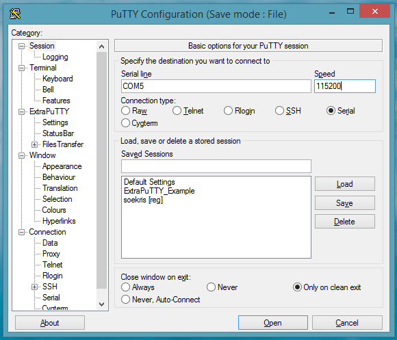
Once you have it installed it is pretty easy to establish a serial connection at 115200, 8, n, 1, as specified by Soekris. You click on the “serial” tickbox and enter your computer’s serial port (in my case it’s COM5) along with the specified speed (115200bps):

ExtraPutty-configuration

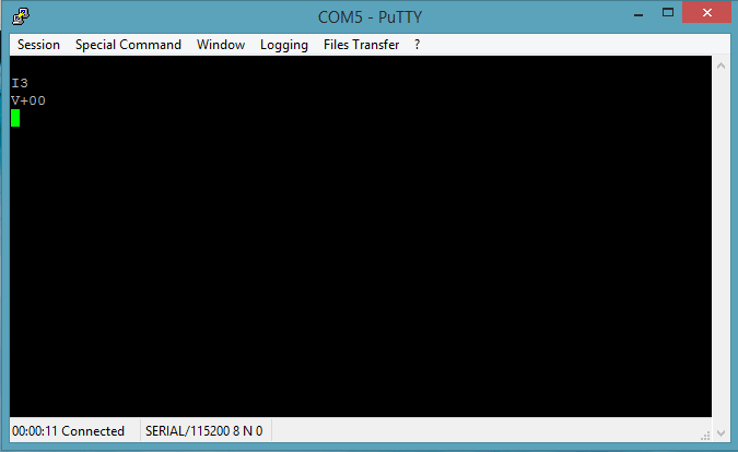
You click on “open” and you get a black terminal screen. You now need to power on the DAC. Once you do that, you should get something like this:

ExtraPutty-after-power

This means that everything is fine. You might see an “I0” instead of an “I3”. That is OK.

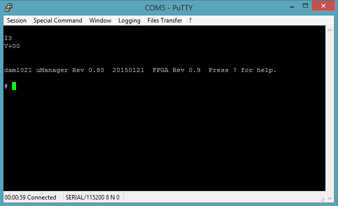
Now you need to get to the uManager prompt. You type “+++” and wait for a second. You will not see the “+” characters as you type them. That is OK. You will get this:

ExtraPutty-uManager

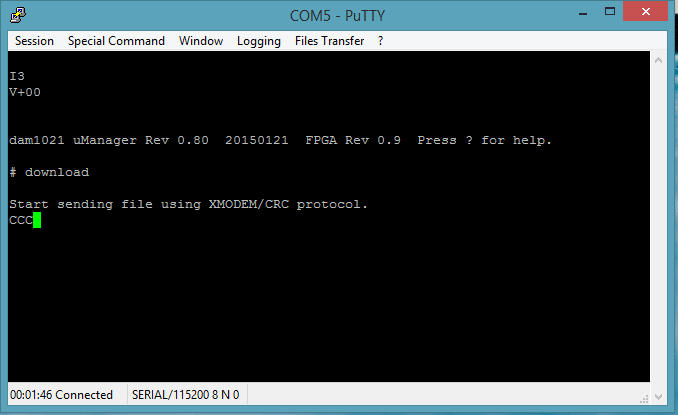
Now type “download”, followed by Enter. You will see something like this:

ExtraPutty-uManager-send

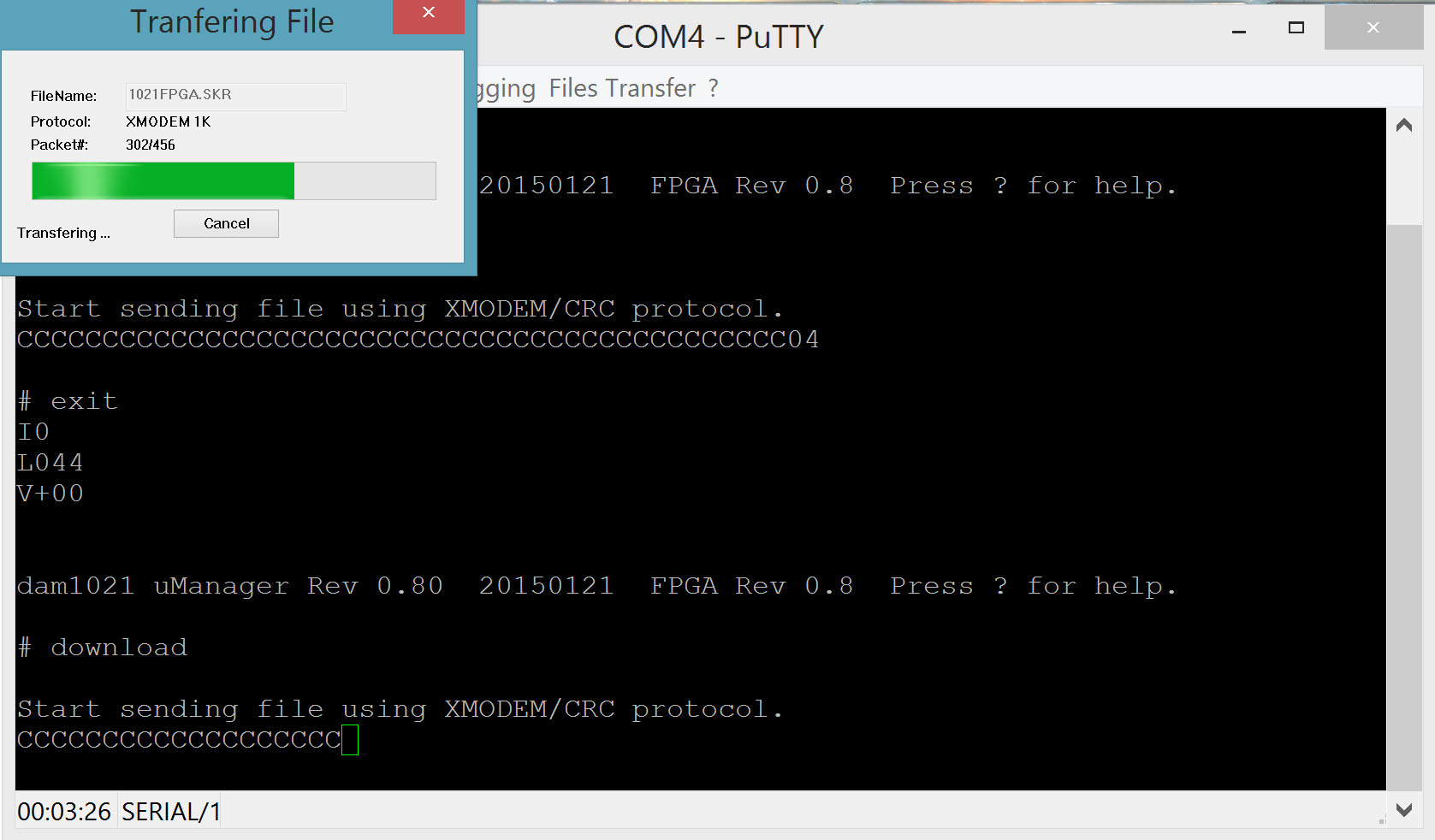
This means that you have 30 seconds to begin sending your file. To do that you click on File Transfer -> Xmodem 1K -> Send. Select your firmware file and off you go!

firmware upload (crop)

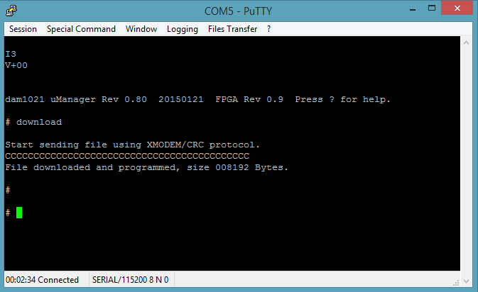
When the transfer completes you will see something like this:

ExtraPutty-uManager-done

One thing – do not forget to give the “update” command once you have uploaded the code followed by a “y” and return.

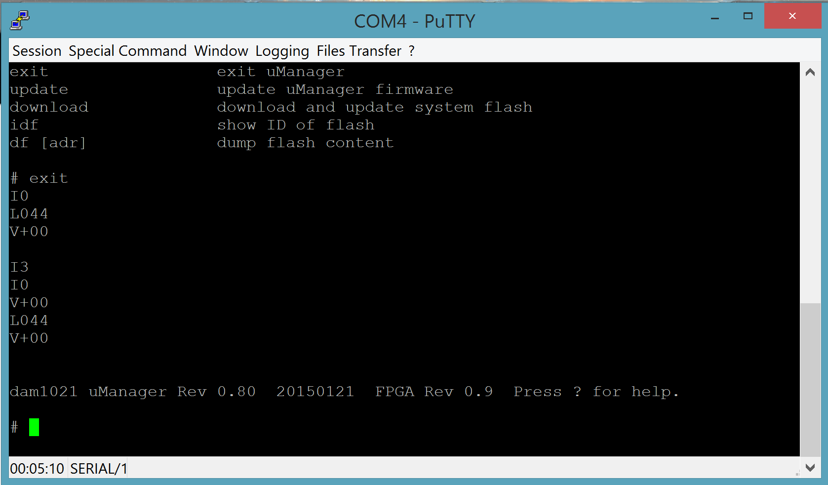
Next you type “exit” (and Enter) to exit the uManager prompt and you are ready to power cycle the DAC. Once you have done that, you repeat the above steps to get to the uManager prompt and you verify that you have successfully updated the firmware. You should now be at FPGA firmware 0.9!

firmware upload 0.9 installed (crop)

If are having problems connecting, such as getting garbage like this in your serial console:

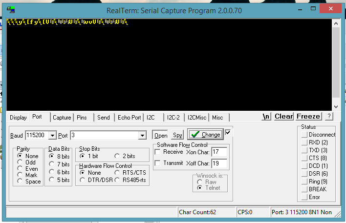
screenshot terminal jibberish 2

chances are that your USB to serial adapter is not a “true” RS-232 interface, but outputs TTL levels instead. You can confirm that by measuring the voltages between GND and the RX & TX pins. You should be getting zero volts in one case and about -9V in the other. If you are getting 3.3 or 5 volts, your interface will not work with the DAM. You should try to find a proper RS-232 interface.

The Soekris R-2R DAC

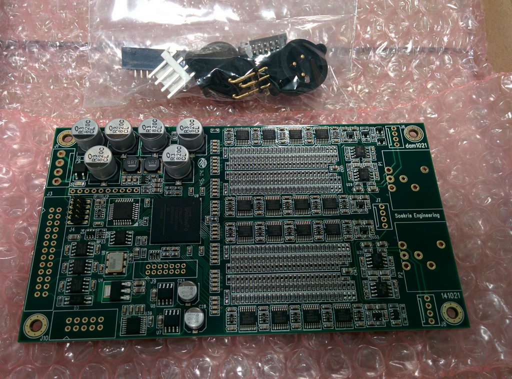
The UPS guy just dropped off my brand new Soekris R-2R DAC:

2015-01-30 13.55.04_resize

Also known by the very bland designation “DAM1021”.

It is a sign-magnitude R-2R DAC (a.k.a. “ladder” DAC), meaning that it is quite different in operation than the regular run-of-the-mill DACs.
It is more like a PCM1704-based DAC but with 192KHz+ support plus a bunch of high tech goodies, such as a built-in FIFO buffer.

It is available in three versions, with resistors of different tolerances (0,01% (high grade), 0,02% (mid), 0,05% (basic)). I got my hands on the 0,02% version.

It has three inputs:
1) I2S (electrically isolated)
2) Coax s/pdif
3) TTL for a Toslink receiver

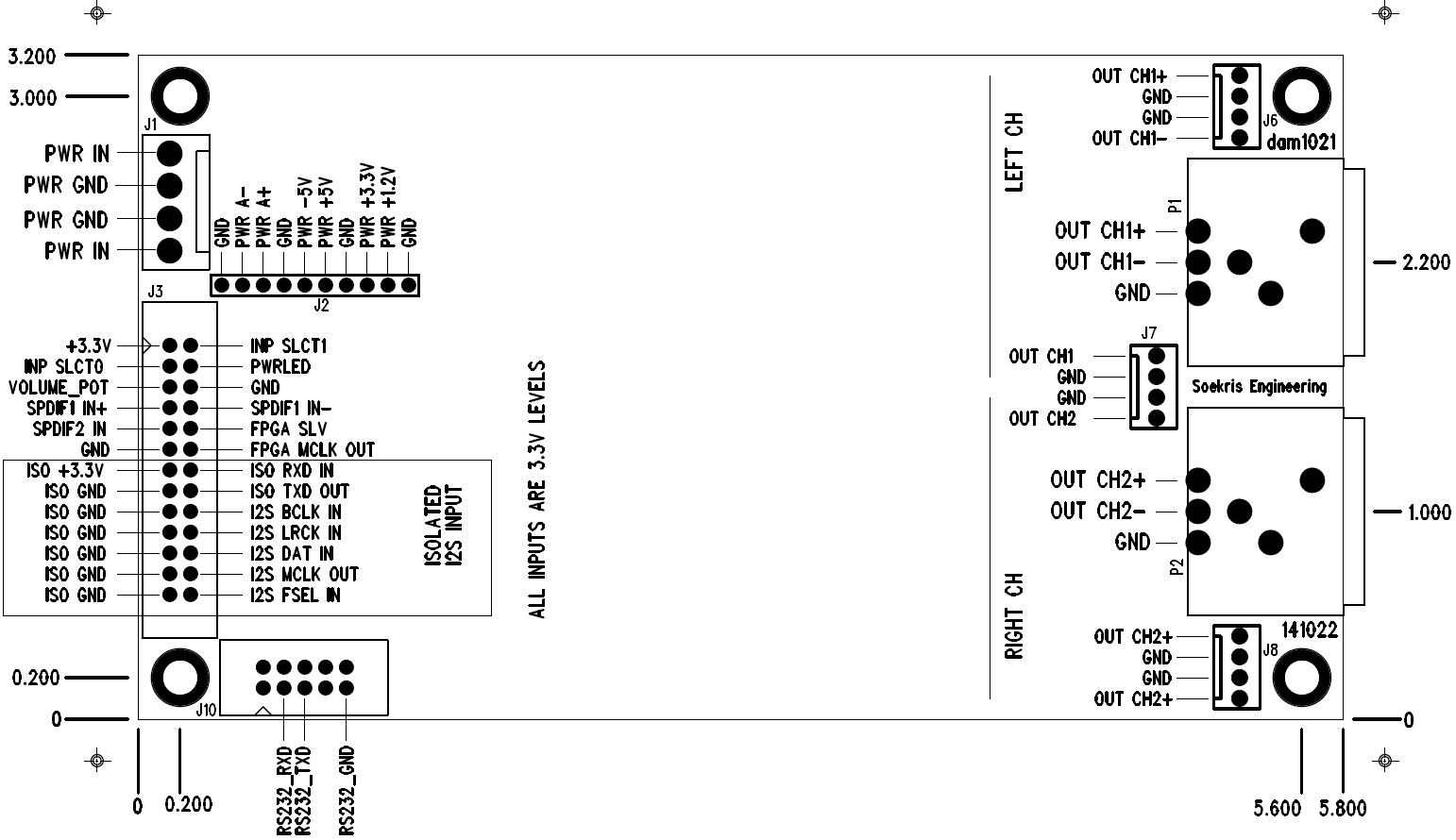
Board-diagram

It is powered directly by a 2 x 7-8V transformer, but may be powered by a bipolar DC power supply.

It outputs a single ended signal at 1.4V RMS and also has a buffer for balanced output at 4V RMS.

It has a serial port for firmware upgrades as well as control.

I have already began work on a Soekris R-2R version of my TFT HiFiDuino Arduino code, tailored to controlling this particular DAC via its serial port.

The board will of course get its own page pretty soon.. Edit: the board now has a page.

To do: hook the board up and actually listen to it play. Stay tuned.

TFT HiFiDuino v2!

It’s official: Version 2 of the TFT HiFiDuino controller is complete!

There is a number of changes, thus the new version:

  • New minimal display mode as default. Goes into full display when changes are to be made to parameters.
  • Full graphics support in the minimal display.
  • New proportional fonts (TrueType).
  • New IR code. Now supports a much larger range of remote manufacturers.
  • Support of MCP23008 IC to control misc devices.
  • New option to set 0db as default (power-on) volume for connection to a preamp.

The code is (and will remain) compatible with my current shield. (Hint: shield v2 is also coming up!)

New requirements:

Plus the good old UTFT library.

I am including the necessary fonts and bitmaps in the ZIP. The fonts should go into your UTFT & UTFT_DLB directories, usually found in the Windows user’s Documents folders (for example, here: c:\Users\<user name>\Documents\Arduino\libraries\UTFT_DLB\).

The bitmaps should go into your sketch’s folder.

I have included in several places in the code SerialUSB output for debugging purposes. It is commented out in this release for performance purposes. However, it is very easy to re-enable for either debugging or viewing of the IR codes sent to the Arduino. You may use these IR codes to customize the code to support your remote by changing the relevant #define statements in the Remote control definitions section.

Due to code size and performance requirements I’m afraid that from v2 onwards TFT HiFiDuino will only be compatible with the Arduino Due. Sorry, it’s the price to pay for nice graphics. Thankfully, it’s a pretty low price. 😛

You may download it here: TFT_HiFiDuino_v2.xx (43666 downloads ) (Note: As always, the code on this page may not be the current one, i.e. there may be a newer version available. The latest version is always up at the project’s official page.)

I will soon update the code’s official page to v2.

IMG_8600_resize

Laying out a display is hard work, Part 2

A couple of weeks back I wrote that I was working on the next version of the TFT HiFiDuino code and that I was struggling with its new aesthetic.

I was considering something resembling this: 2014-12-14 21.50.50_resize

But, I did warn you that the final version would probably look nothing like this. I was right.

Two weeks have passed since then and I am very close to a v2 release. The aesthetics are 99% complete and I am just ironing out a few bugs.

This is the final look: IMG_8570_crop_res IMG_8567_crop_res

Stay tuned.. v2 will be out before the end of 2014!

New page: Hypex UcD400HG Power Amplifier

IMG_3839_resize

Back in 2011 I built a 3 channel power amplifier based on Hypex UcD400HG modules and their matching SMPS400 power supplies. It has been my favorite amplifier ever since.

Now it has its own page on my blog, filled with construction details and photos. I have also included the schematic and PCB for the custom AUX power supply that I designed for the UcD400’s input opamp.

The Raspberry Pi: Audio out through I2S

There are currently four ways to get audio out of the RPi:

  1. Use the audio out 3.5mm jack. It’s very easy to get it to work, but the sound quality is pretty bad, since it uses PWM to generate the sound. Due to that, its real resolution is in the neighbourhood of 11 bits. We have no use for that.
  2. Use the HDMI port. It works OK, but is useless to us audiophiles.
  3. Use a USB to I2S adapter, such as an Amanero or an XMOS-based device. Now we’re talking. They work quite well, and the quality of the I2S signal is dependent largely on the technology used (CPLD vs. XMOS, etc) as well as the quality of the on-board clocks. The problem is that they add another link to the audio chain, as well as increase the cost. Remember, the RPi is supposed to be a low cost solution.
  4. Use the GPIO pins of the RPi to get direct I2S output. This sounds way more interesting, right? Let’s try that!

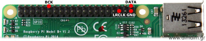
According to several sources on the Net, this is the pin out:

Raspberry_Pi_B_Plus_I2S_out

You will probably notice that the RPi does not support MCLK output. This means in practice that your DAC will need to have its own on-board clock (or internal PLL / oscillator or whatever). We can live with that.

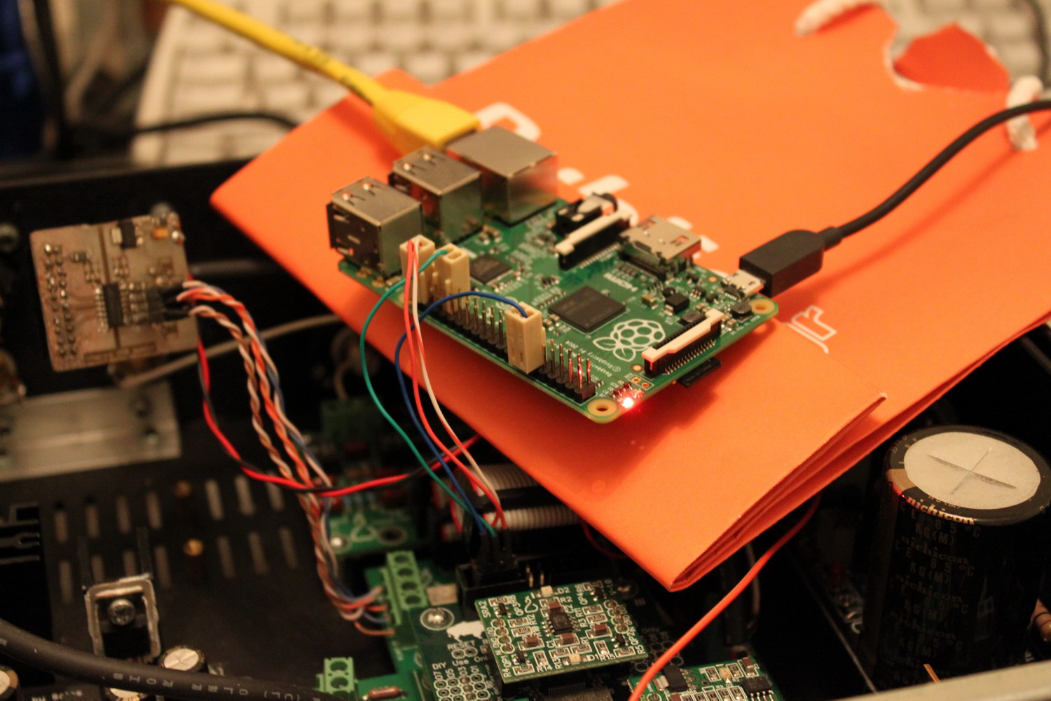
Luckily, my Buffalo III has its own clock (of course it does!) and thus can be connected quite easily. Let’s try that:

IMG_8297_resize

Now we have to configure the software for I2S output. For my distribution of choice, Archphile, it’s a piece of cake: http://archphile.org/howto/i2s-dacs-and-the-raspberry-pi/

Audio playback works just fine!

Well, almost fine..

You see, in theory the RPi has a bit of a problem with its I2S output. Since the only clock onboard the RPi is a 19.2MHz crystal, it should have trouble generating proper clocks for its I2S output. For example, for 44.1KHz audio, the LR Clock must be running at precisely 44.1KHz. That is not possible, since the frequency is not a multiple of 19.2MHz. Thus, the frequency can be either 19.200.000 / 435 = 44.138KHz or 19.200.000 / 436 = 44.0366KHz. This is a limitation of the Broadcom BCM2835 in conjunction with the 19.2MHz crystal and there is nothing that can be done.

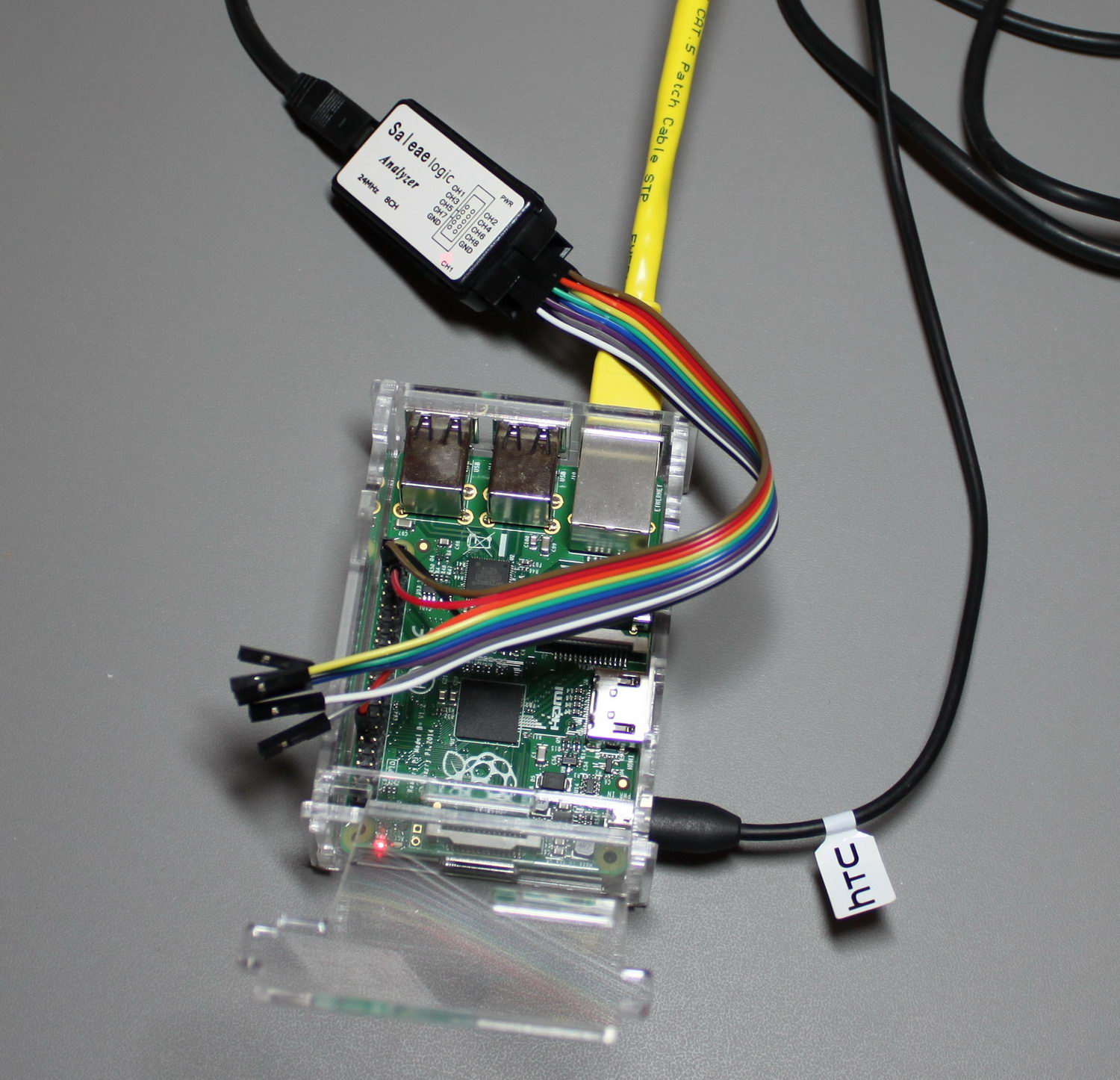
In order to confirm the theory, I decided to run a few tests. I hooked up my logic analyzer to my RPi, set it up for I2S output, and fed it some 44.1KHz music.

IMG_8453_crop_resize

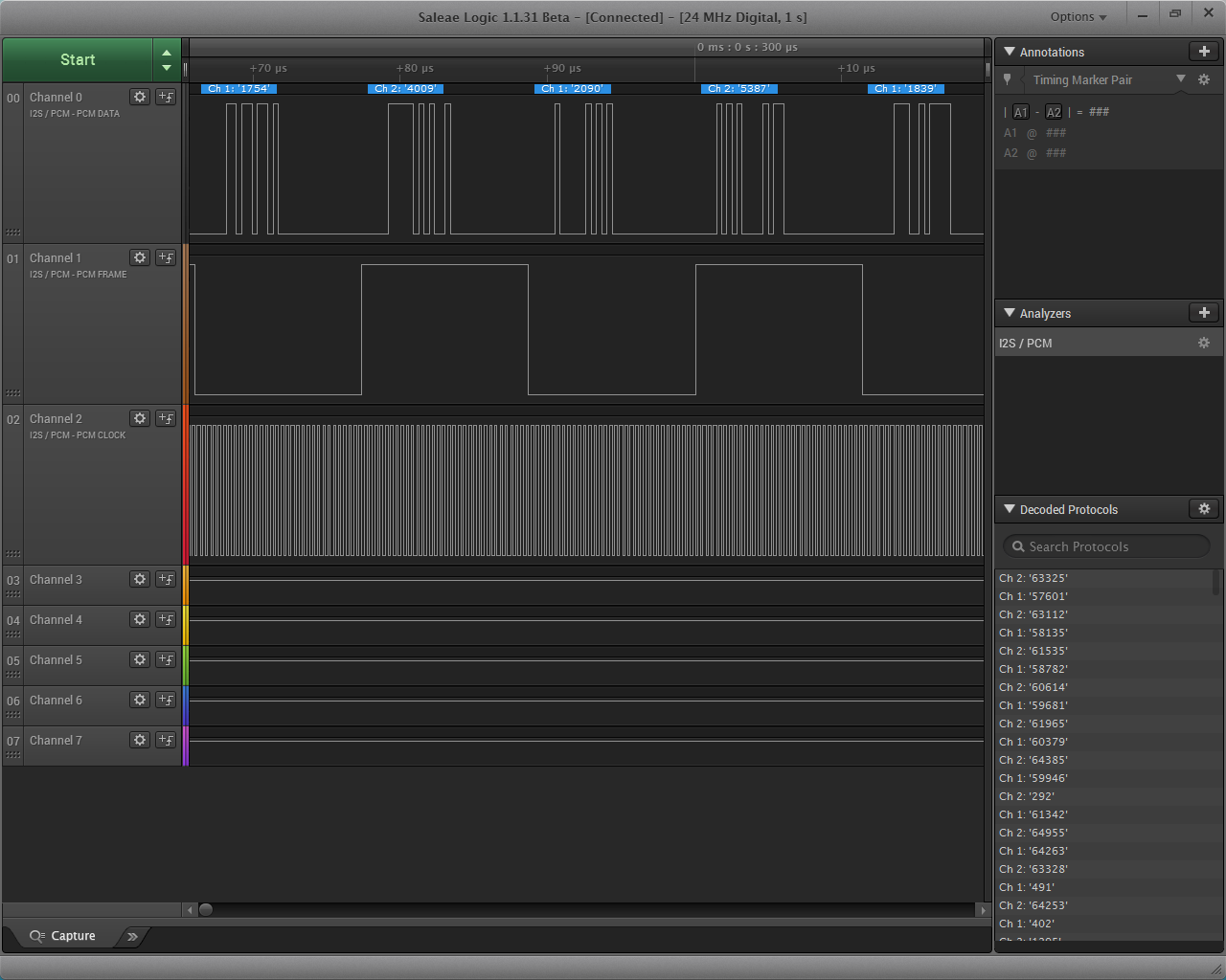
I took 1 sec worth of samples with my logic analyzer, configuring it for I2S signal. I got this:

logic analyzer 4

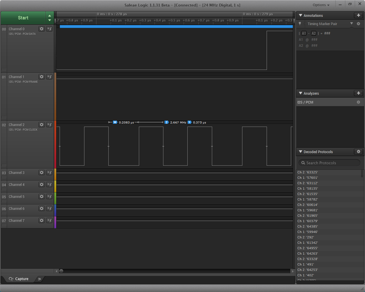
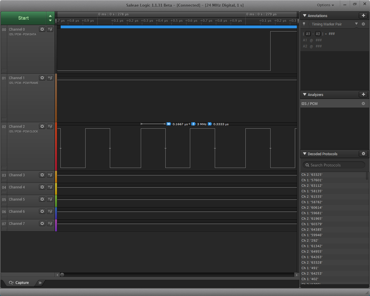
The PCM Clock is already appearing a little dodgy. Let’s zoom in:

logic analyzer 5

logic analyzer 6

As you can see, the pulses do not have the same duration. They appear to alternate between two values. So it is obvious that the signal has jitter. A lot of jitter. Since we’re here, let’s have a look at the LR Clock signal as well:

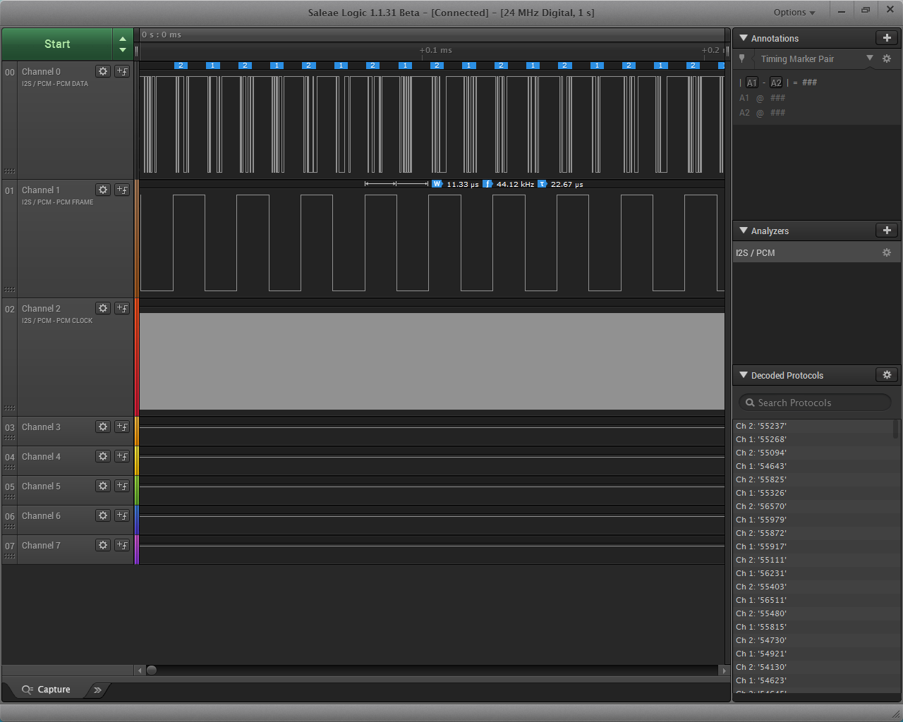
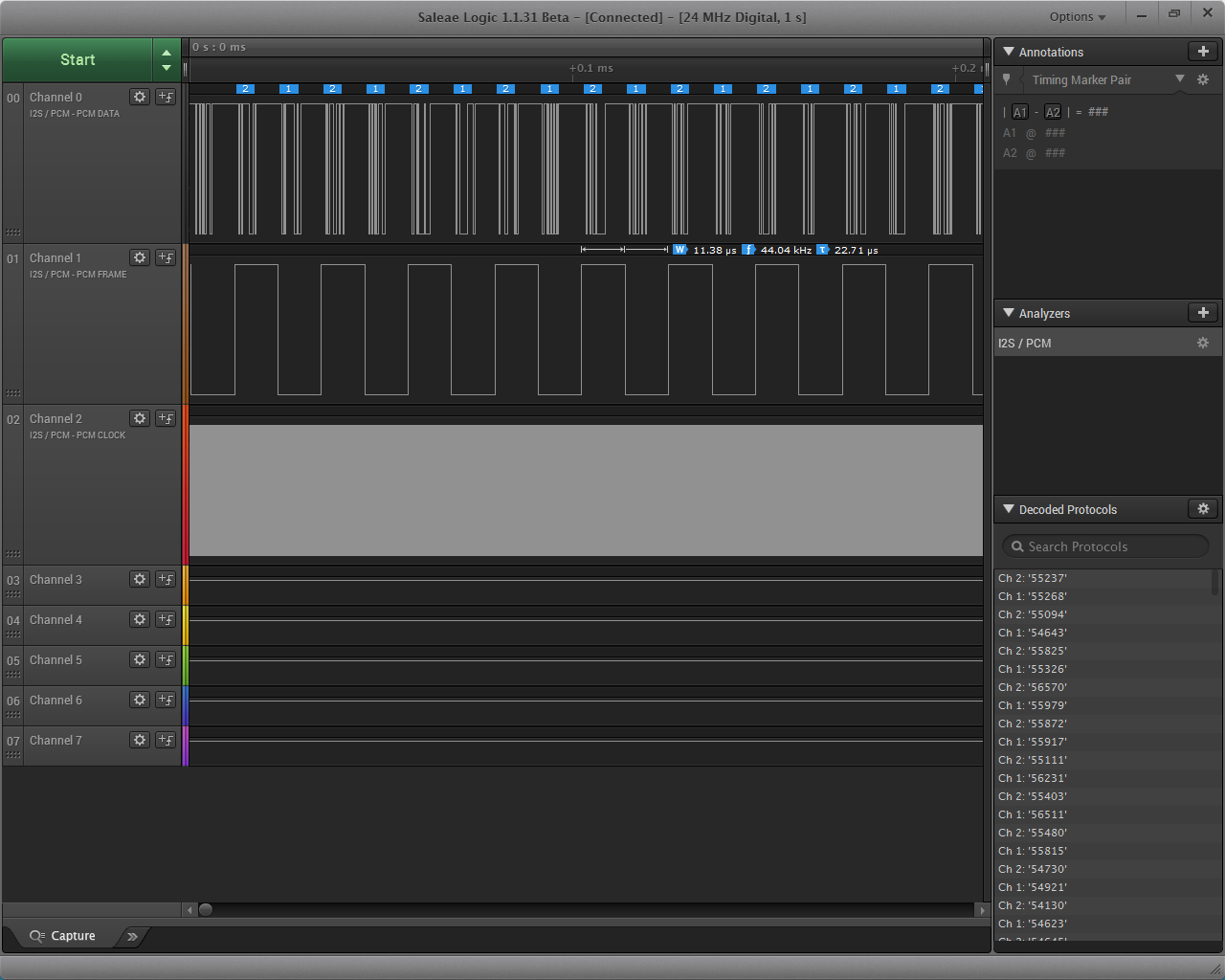
logic analyzer 7

logic analyzer 8

The duration of the pulses appears to alternate between 11.33μS and 11.38μS, giving respectively 44.12KHz and 44.04KHz, values very close to the ones I calculated previously.

So, the theory is sound and the RPi’s clock is not up to snuff by strict standards. What this means is that the RPi’s I2S output is not capable of “Hi End” audio transmission. It is essentially not bit perfect (edit: this is not correct, strictly speaking. It is in fact bit perfect, it is just not “proper”.).

In the real world, chances are that this problematic clocking will not be particularly audible under normal circumstances, say with a normal-specc’ed sound system. But an audiophile should definitely steer clear of the RPi’s I2S output, instead opting for a USB to I2S interface.

The Raspberry Pi: Low cost music streamer

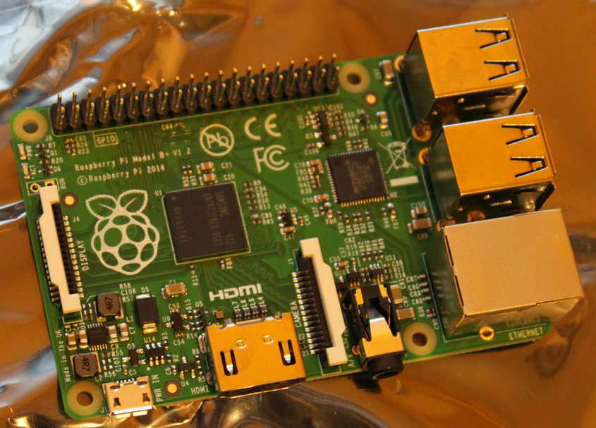
Enter the Raspberry Pi B+:

Raspberry Pi B+

It features:

  • A Broadcom BCM2835 SoC processor running at 700MHz
  • 512MB of RAM
  • A Micro SD slot for storage
  • A 10/100Mbps Ethernet port
  • 4 x USB2.0 ports
  • An HDMI output port
  • An analog audio / composite video output port
  • A 40-pin expansion header, exposing 26 x GPIO ports
  • A camera and a display interface port

Somehow they have managed to cram all that in an almost credit-card sized PCB.

And it costs less than 40€.

It runs Linux (of course..). There is a large number of general-purpose distributions available, as well as a few custom built ones. One of them is Openelec (an XBMC Media Center distro), another one is Volumio (an audiophile music player), a third one is SqueezePlug (it emulates a number of Media Servers, like Logitech Media Server, MediaTomb, MiniDLNA, etc. It also works as a Squeezebox (client)), etc.

So far, my favorite distribution is Archphile, an audiophile linux distribution. It may not have the polished look of Volumio or play 1080p video like Openelec, but is plays music wonderfully through a USB port (or through I2S if you are more of a DIYer).

So, what am I doing with it? I wanted to put a music streamer in my kitchen. I already have two Squeezeboxes in other rooms, so for the kitchen I thought I would try something more interesting.

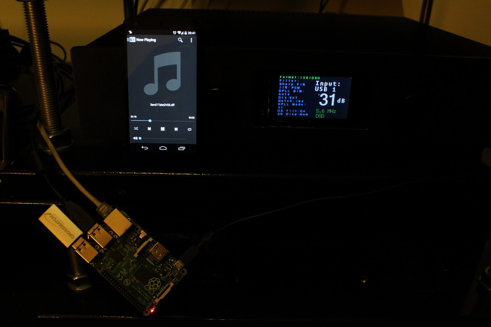
But along the way, I discovered that it is a lot more useful than that. A very useful (and very rare) feature it has is the ability to bitstream DSD audio (a.k.a. SACDs):

RPi outputting DSD to Buffalo DAC

Raspberry Pi B+ outputting DSD to my Buffalo DAC

So now I’m considering adding an RPi network music transport to my main system.