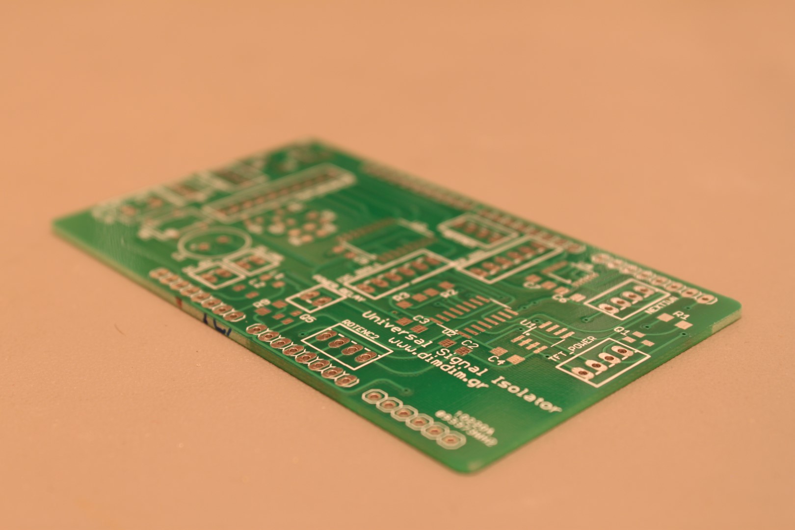
I’m talking about my new Universal Signal Isolator PCBs:
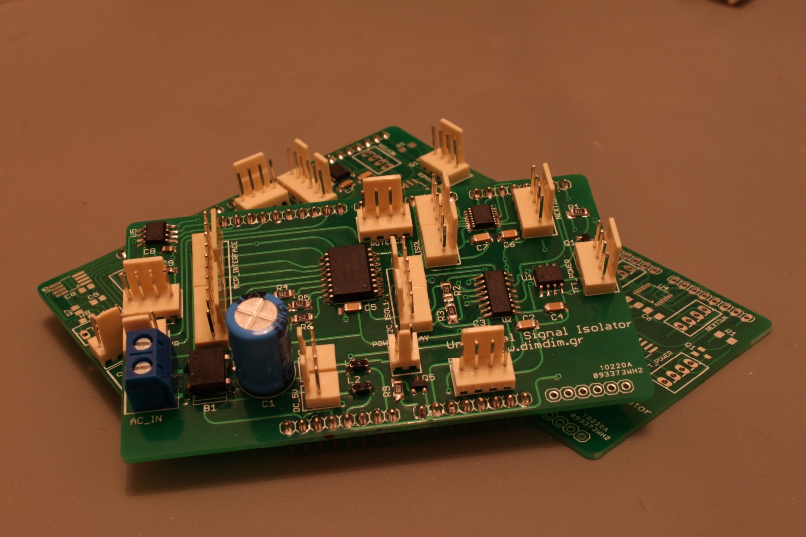
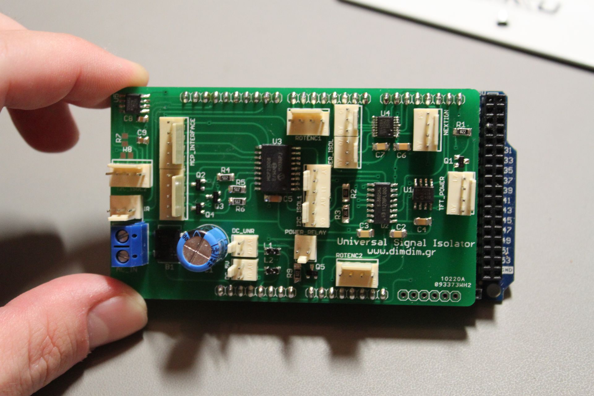
I built one to test it out and everything seems to be working as it should. Next step is a page for the project, with schematics, a BoM and build instructions.
It is compatible with the current versions of both the ArDAM1021 and TFT HiFiDuino projects.
(Note: As always, the code on this page may not be the current one, i.e. there may be a newer version available. The latest version is always up at the project’s official page.)
I will also update the code’s official page with the new version of the code.
Three weeks back I released the first public alpha of the ArDAM code, stating that it was very very alpha. I was meaning every word of that sentence.
Since then, Soren has released the new firmware for the DAM and I have resumed work on the project. Today I am happy to release the first usable version of the code (v0.74):
A few years back I designed a little Arduino shield who’s main function was to provide electrical isolation between an Arduino and a DAC (specifically a TPA Buffalo III).
The years have passed and my needs have changed with the introduction of the dam1021 DAC and its serial interface. My first though was to design a new shield specific to the dam but then I said “why not design a universal isolator shield?”. It would provide electrical isolation for both I2C as well as serial signalling.
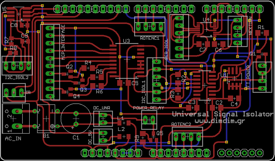
Thus was born the Universal Signal Isolator shield for Arduino DUE & MEGA:
OK, it does look a lot more complicated than my first shield but remember, you only need to solder in the parts that your DAC actually needs.
So, what does this thing do?
1) Electrical isolation of I2C signals, complete with support of 8 isolated inputs or outputs (via an MCP23008 IC). Three of the MCP’s pins are high current outputs (up to 100mA).
2) Electrical isolation of up to 2 serial ports (implemented with an Si8642).
3) Electrical isolation of the second I2C interface of the DUE (implemented with an ADUM1250).
4) Powered either by 5VDC, 8-15VDC (non-regulated) or 7-12VAC (includes support for on-board rectification and filtering).
According to Soren, these are the changes to the firmware:
* PLL Clock Sync at sample rate change cut down to less than 0.2 second * Isolated Serial port now works, note that port is at 3.3V cmos level * Serial Port now interrupt driven, no character loss at high speed * Volume Control now is -80db to +10 db, and phase bug fixed * Volume Control also now have zero crossing detect * Power Off plop can be reduced to 1/3 by adding a single 27K4 resistors, see picture attachment * FIR1 filters doubled in size, so max 2032 coeff @ 44K/48K, 1016 @ 88/96K, 508 @ 176/192K, 127 @ 352/384K * You can now select four sets of filters, named Linear, Mixed, Minimum and Soft. * FIR1 coefficients are now 1.31 format, filters should be good down to around -150 db * Stock filter now have improved deemphasis filter * Input Source Select bug fixed * New mode setting: Normal, Inverted, Balanced Left, Balanced Right * The tiny bug on signal saturation on -full scale fixed * Should now be possible to do balanced and crossovers by parallel the inputs and connecting the isolated serial ports together, more details to follow
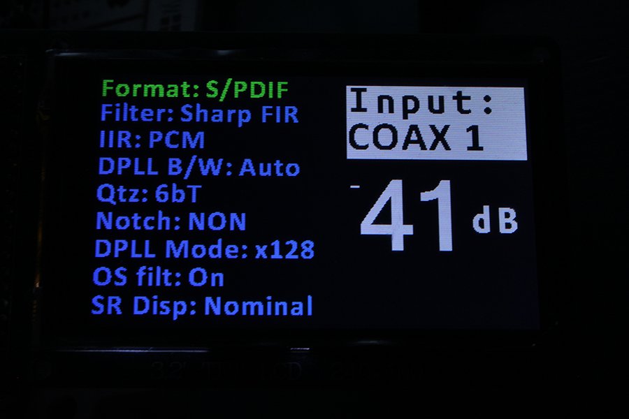
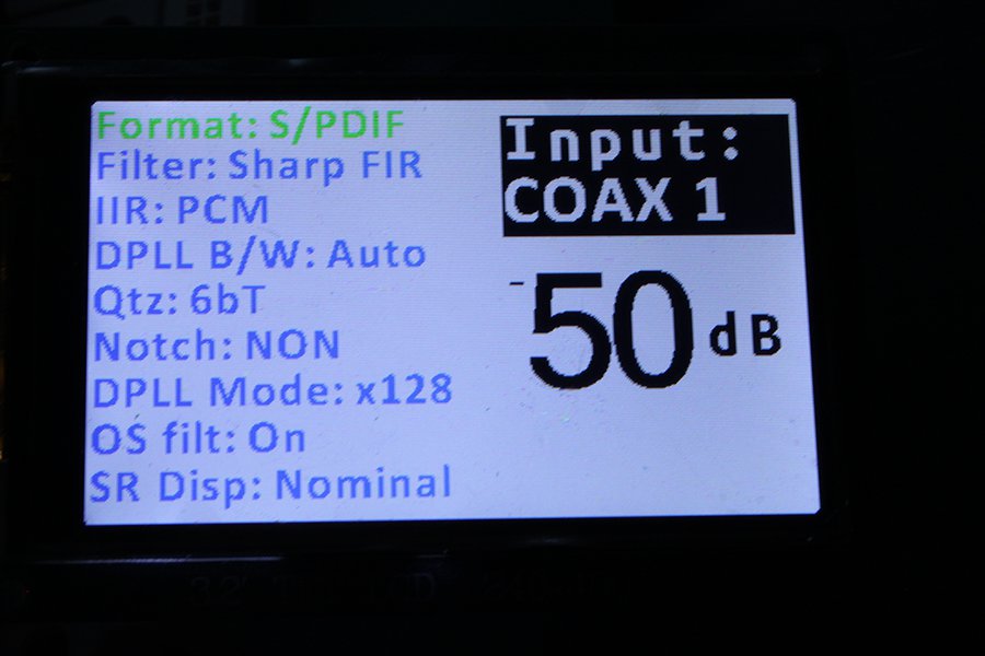
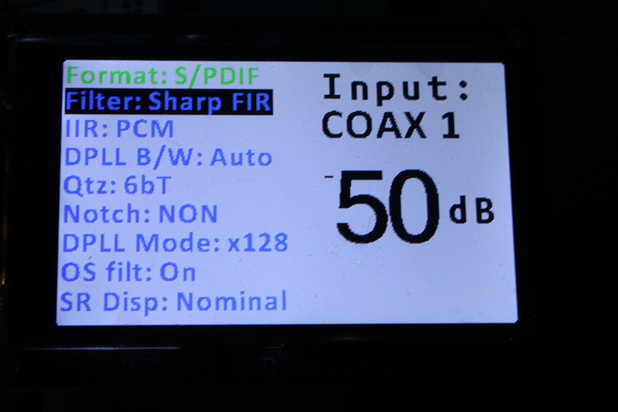
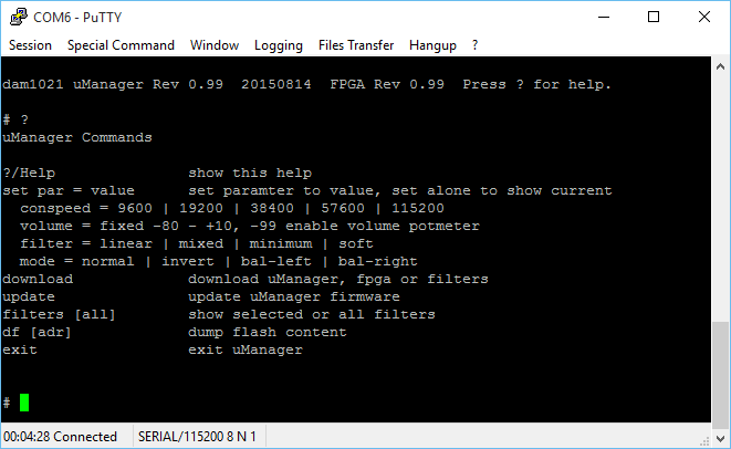
I had some difficulty uploading the new firmware but that was due to Windows 10 and ExtraPuTTY not playing along very well. I got an “Error File not found!” message when I was trying to upload the file. When I went to a Windows 8.1 machine everything went as expected. One thing – do not forget to give the “update” command once you have uploaded the code followed by a “y” and return. When the procedure is complete and upon power cycling the board (and entering the “+++” command) you should get something like this:
Both the uManager and FPGA revisions should be 0.99.
The uManager has a few new options:
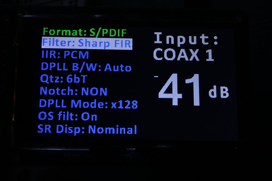
Plus these are the new built-in filters:
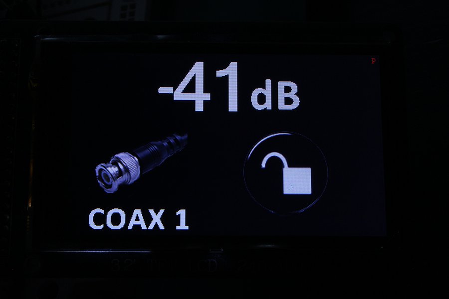
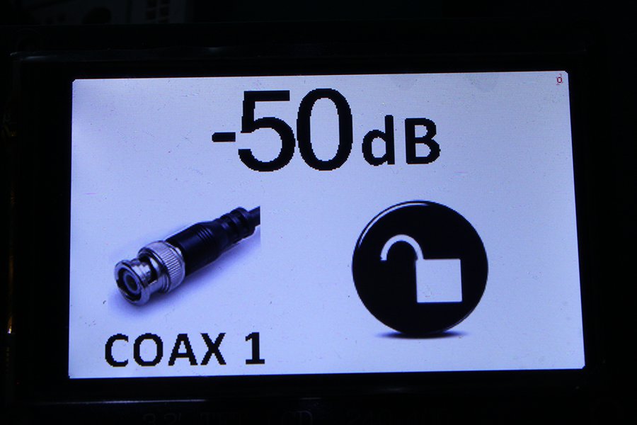
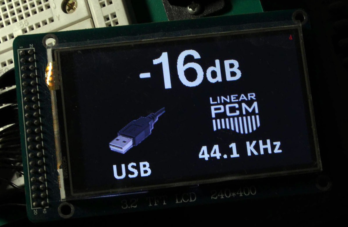
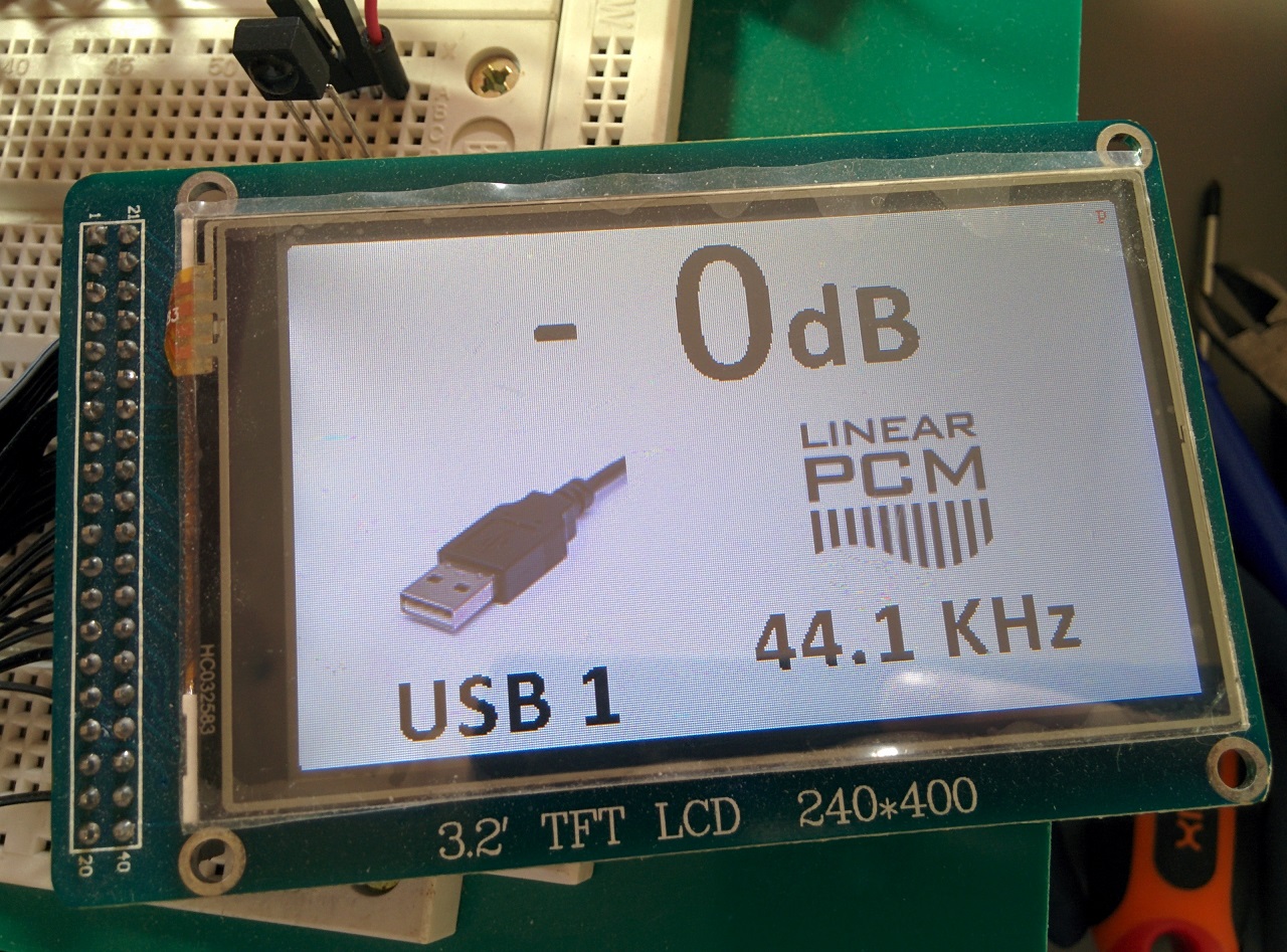
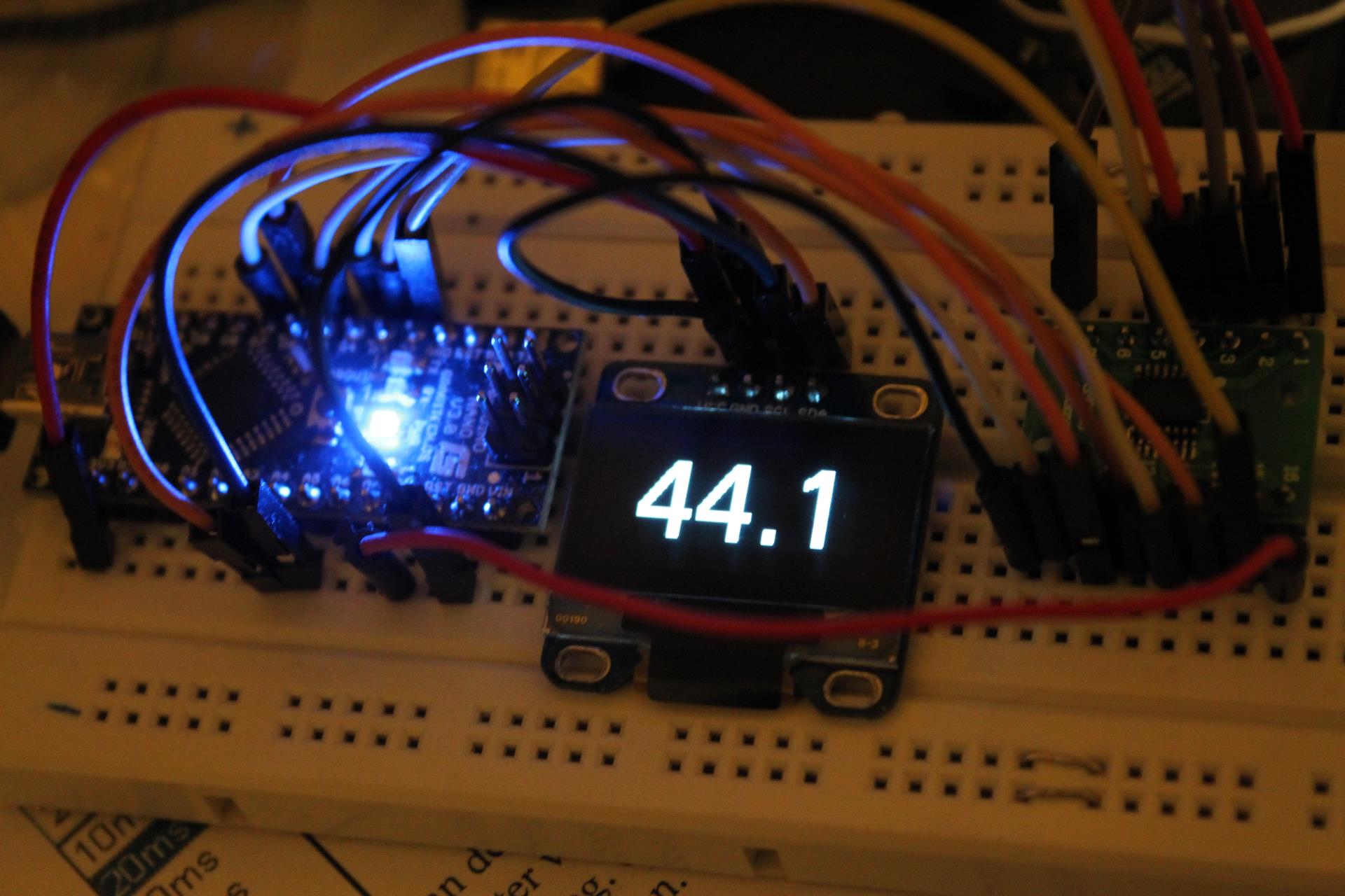
First impressions are very good. The dam now locks much faster to incoming signals, so fast that it’s near instantaneous:
Plus we have very good news on the serial control department. Not only has the isolated serial port been enabled (to be tested asap..) but the RS232 port seems to no longer have problems with my Arduino controller. It probably had something to do with the “Serial Port now interrupt driven, no character loss at high speed” fix. So development of the ArDAM1021 code becomes high priority. 🙂
Zero crossing detection seems to be working fine too – no more glitches during volume adjustments.
All in all I would say this is a pretty good upgrade. Kudos to Soren.
Now looking forward to DSD support on the next upgrade.
A few days ago Soren announced that the release of the new firmware for the dam1021 was close.
In light of that announcement I have decided to release the Arduino code that I had written a few months back, even though it is not quite finished.
I am doing this to help fellow Arduino & dam1021 enthusiasts in their quest of remote-controlled color TFT bliss.
So, for now, no real documentation – this is no polished piece of software, but it works (for the most part).
Since it is based on the TFT HiFiDuino code, you can get started by reading its documentation. It should not be hard to get started with this. The code itself also contains useful comments.
Also, I have come across a strange problem with the serial communication with the dac. In the beginning all is well but after a while the dam no longer responds to the commands that are sent by the Arduino. However, it (the dam) is still sending data back to the Arduino – when the sampling rate changes, the new SR is displayed properly on the TFT.
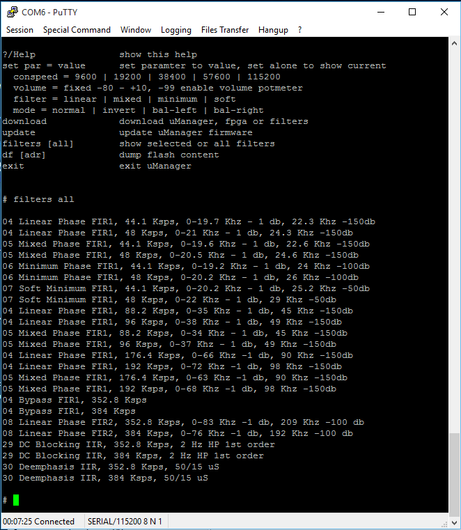
I have verified that the Arduino is indeed sending the commands to the dam:
I hope the problem gets sorted out in the new firmware release.
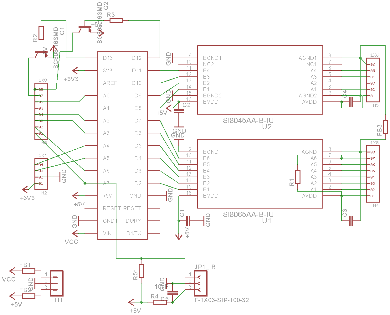
Over at avclub.gr we designed a custom PCB to ease the implementation of the Universal USB to I2S Interface Indicator. It was a joint effort between myself and Manolis (a.k.a. lemon at avclub.gr). I did the circuit design and Manolis did the PCB design work.
This is the schematic of the final version of the circuit:
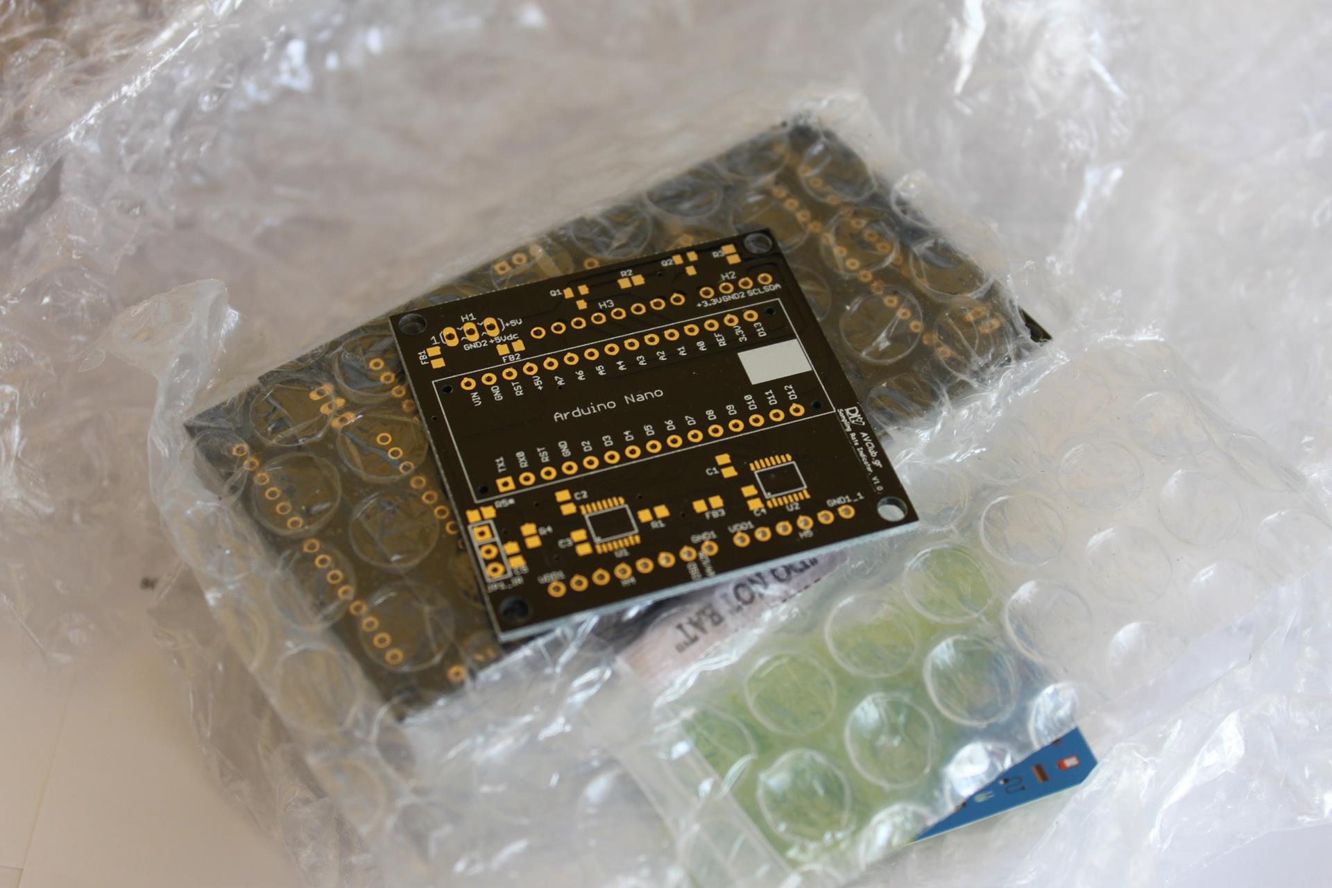
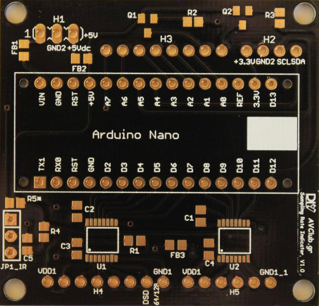
When the PCB design was finalized, a GB was organized. When the GB was finished we placed an order on seeedstudio.com’s Fusion PCB service. About 3 weeks later the PCBs had arrived:
The production quality was truly excellent.
From top to bottom we have:
H1: Header for power. It may be either 5VDC (regulated) or 7-12VDC (non-regulated). Pin 1 is 7-12VDC, Pin 2 is GND, Pin 3 is 5VDC.
H2: OLED display connector. Pin 1 is 3.3V to the display, Pin 2 is GND, Pin 3 is SCL, Pin 4 is SDA.
H3: Header for future expansion. It exposes the unused I/O of the Nano in case it may be of use in the future. The last two pins are buffered by transistors so that they can supply enough current to engage small relays (5VDC, up to 100mA per pin). Pin A7 is connected to JP1_IR as well (see below).
Next up is the socket for the Arduino Nano. You will notice that the USB port should be on the right.
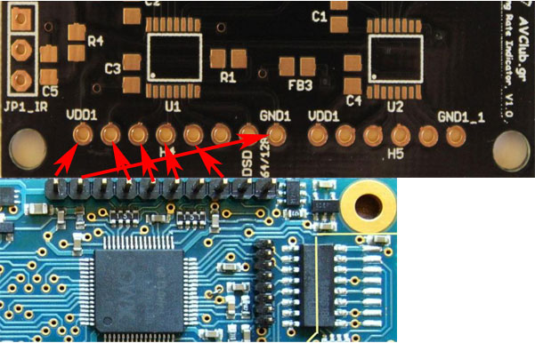
At the bottom of the board we have:
JP1_IR: This is a connector for an IR Receiver module. Software support for this is currently in beta. Pin 1 is signal out, Pin 2 is GND, Pin 3 is power (5V). Note that R4 and C5 provide filtering for the power and should be installed. R5 is an optional pull-up resistor. It should not be installed for normal use.
H4: This is the “dirty” side of the U1 isolator. Pin 1 is Vdd (usually 3.3V or whatever your USB Interface module uses for its logic levels). Pins 2 through 7 are inputs and Pin 8 is GND.
H5: This is the “dirty” side of the U2 isolator. Pin 1 is Vdd (usually 3.3V or whatever your USB Interface module uses for its logic levels). Pins 2 through 5 are inputs and Pin 8 is GND.
Note that in the future a Si8642BA may be used in place of U2. With proper support from the code that will turn 2 of the 4 inputs into outputs, so that they may be used to control a DAC board (for example to select an input).
This is the full BoM:
Part
Description
FB1, FB2, FB3
Ferrite Bead 0805
R1
2.7K 0805
R2, R3
8.75K 0805
R4
100R 0805
R5
10K 0805 (optional)
C1, C2, C3, C4
100n X7R 0805
C5
10uF 10V X7R 0805
Q1, Q2
BC808 or equivalent SOT-23
U1
Si8065AA-B-IU
U2
Si8045AA-B-IU (optionally Si8642BA-B-IU)
In case you want to have your own PCBs made, these are the Gerber files:
You will also need an Arduino Nano, a suitable OLED display and some cables, connectors, etc. (see project page).
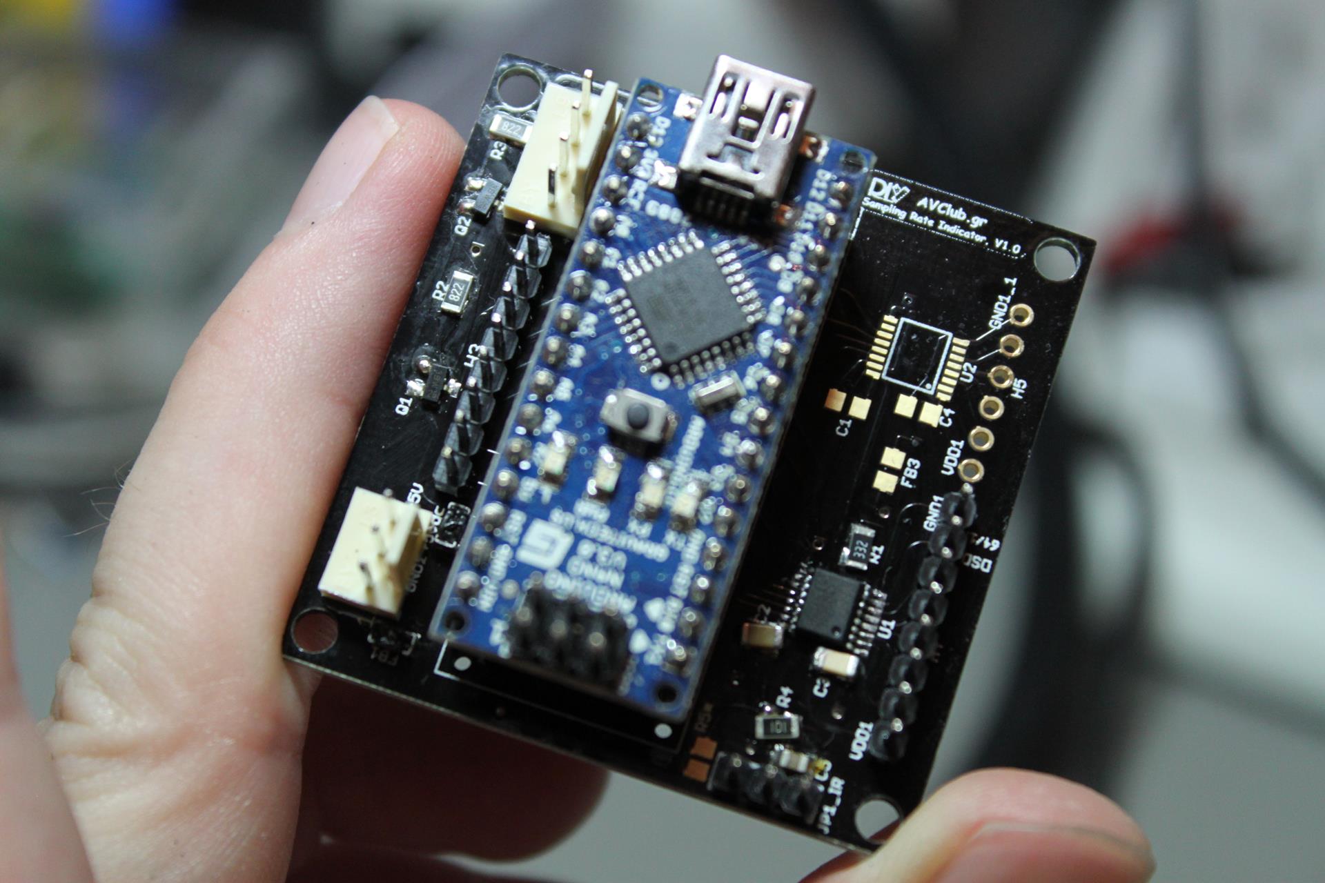
As soon as I received the boards, I built a prototype with whatever components I had lying around (thus the wrong size of most of the resistors & capacitors).
And proceeded to test it out with an Amanero Combo384 board:
Everything worked as it was expected. 🙂
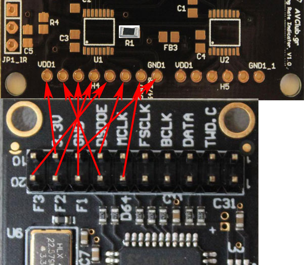
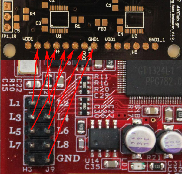
At the moment this board (and relevant Arduino code) has been tested with the following USB to I2S interfaces:
Amanero Combo384 Note that R1 should be installed for proper operation.
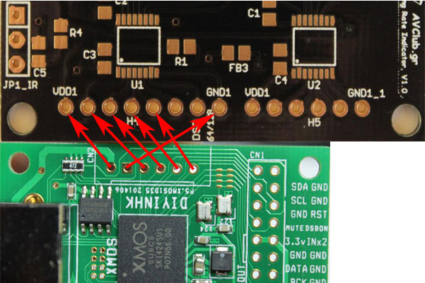
DIYINHK XMOS
JLSounds I2SoverUSB
Luckit WaveIO
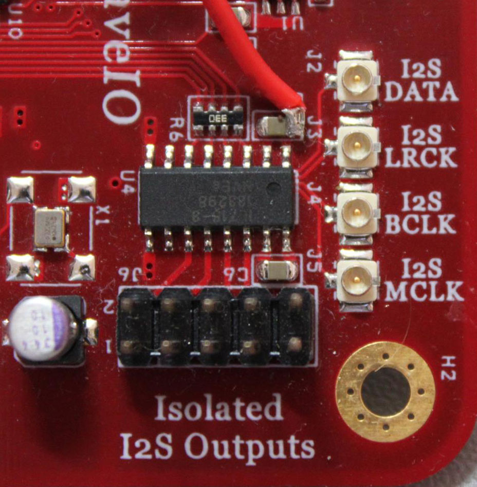
You will notice that there is no Vcc pin on J9. In order to power the isolator, we will have to “steal” power from elsewhere on the board. A good place to tap is the power pin of the on-board I2S isolator, just to the left of the I2S LRCK U.FL:
Following up on a number of feature requests made over at avclub.gr I made a few rather interesting additions to the code:
1) The OLED display will show the type of signal (PCM or DSD) for 3 seconds if a change in signal type occurs. Only supported on USB interfaces that support it (obviously).
2) IR remote control support via the well-known IRremote Library. Support for power on/off and source selection (S/PDIF or USB).
3) The OLED display will display the name of the selected source, permanently if it is S/PDIF or for 3 seconds if it is USB.
More details on the new features will be added to the project’s home page, as will the new version of the code.
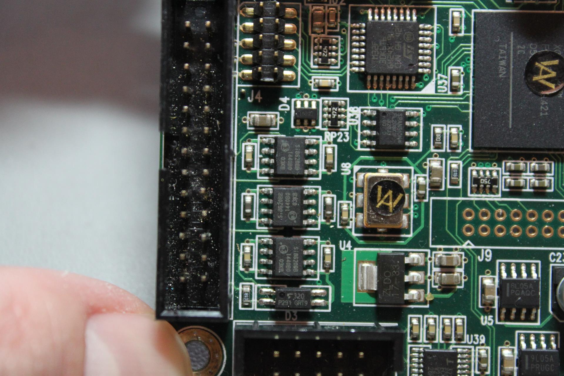
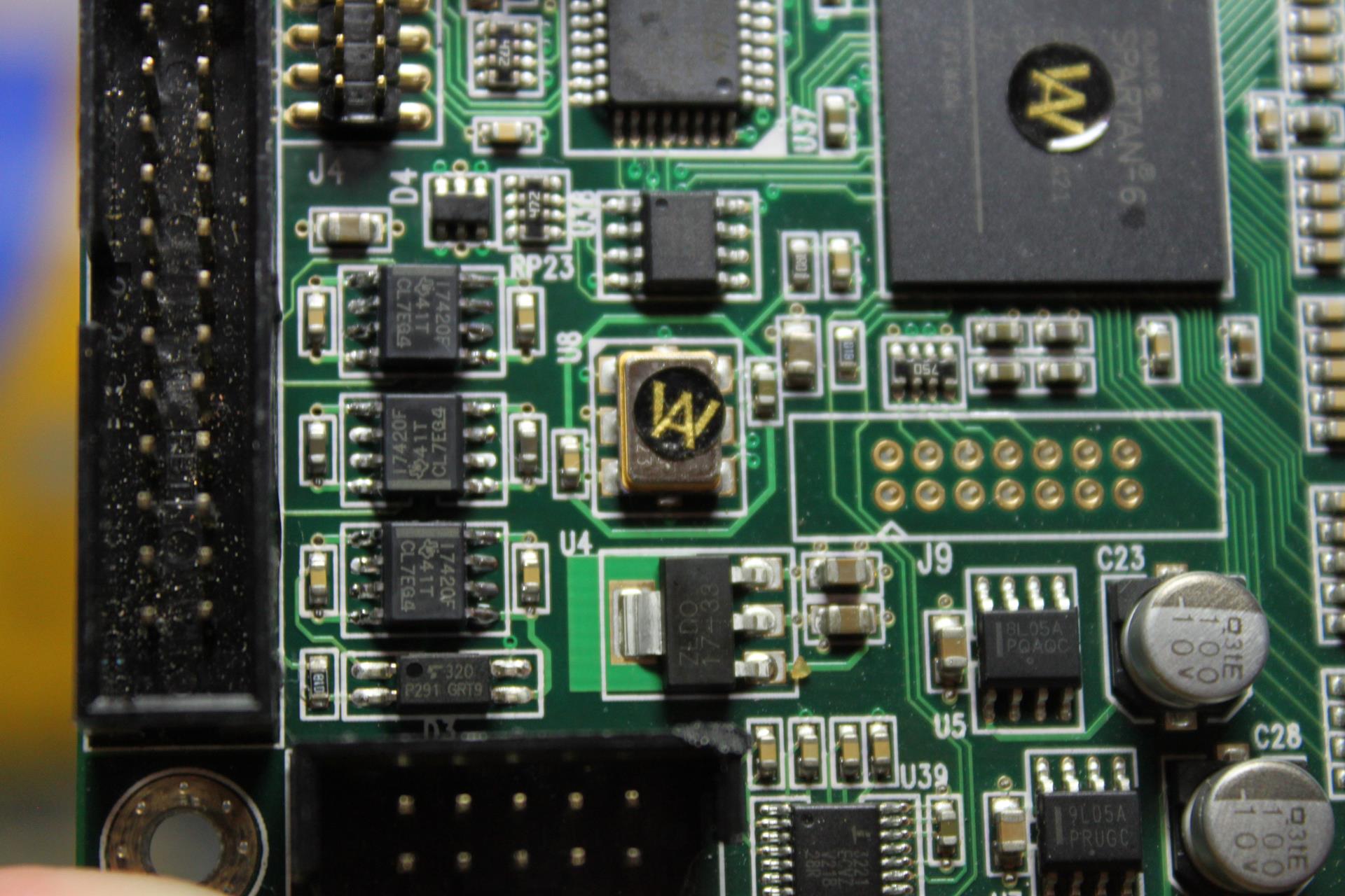
A friend of mine had a little accident with his DAM1021 which resulted in him frying the on-board isolators.
We are talking about these three ICs, with part number “SI8620BB-B-ISR”.
It turns out that the specific ICs are at their End Of Sale, so both Mouser and RS did not have them in stock. Luckily, it turns out that the TI ISO7420FEDR is a good alternative. Unfortunately, it is also about 2.5 times the price of the Si part, but what can you do.. The order was placed, in time the ICs were delivered, and it was time to do the work.
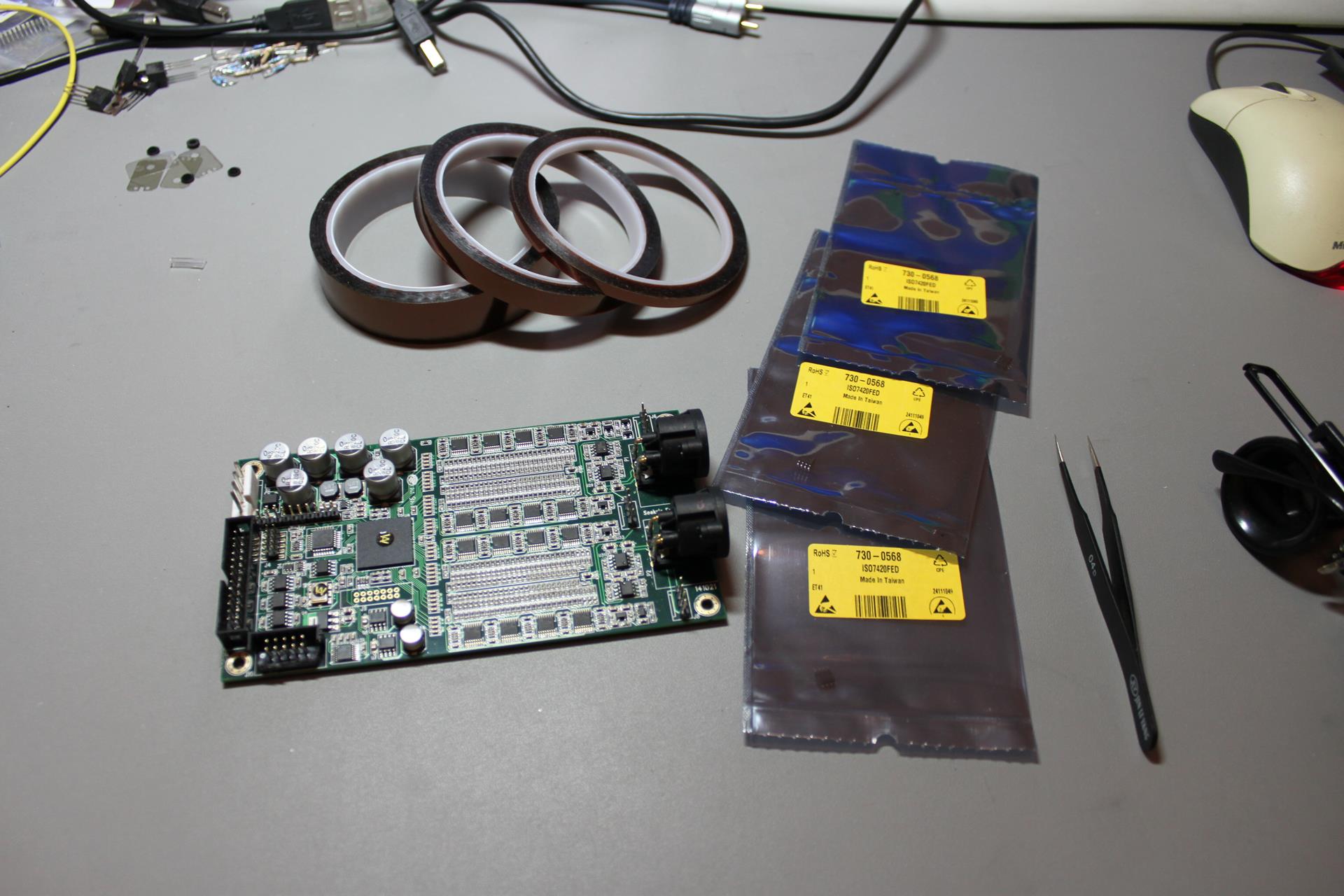
This is what my workbench looked like:
You see the DAM board, a collection of different width Capton tapes, the ISO7420FEDR ICs and my favorite set of tweezers. In the far right you see part of my magnifying glasses. They are necessary for repairs of SMD stuff.
What you don’t see is my hot air rework station which is also necessary.
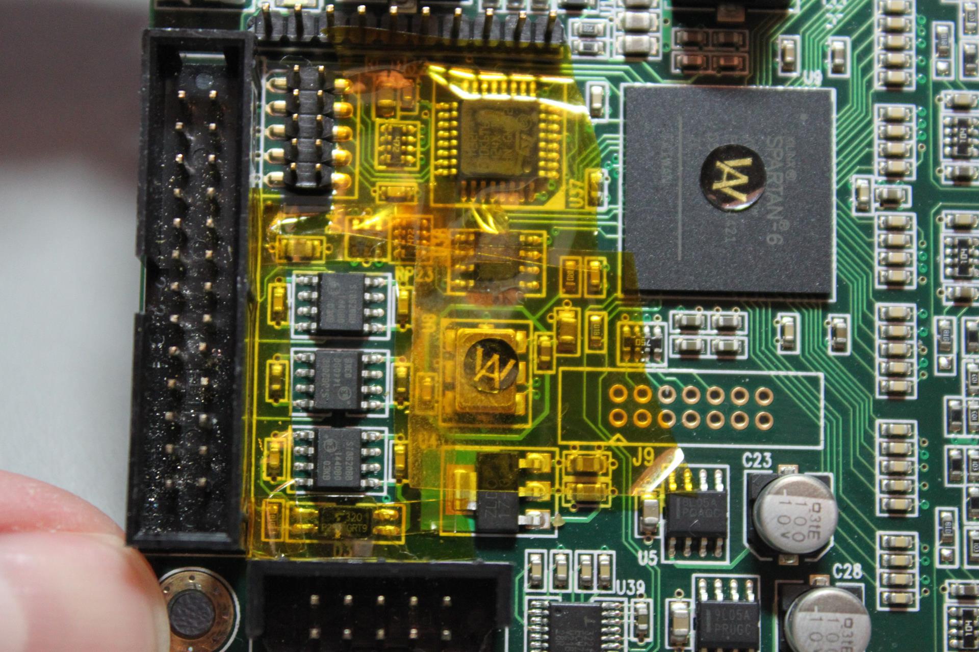
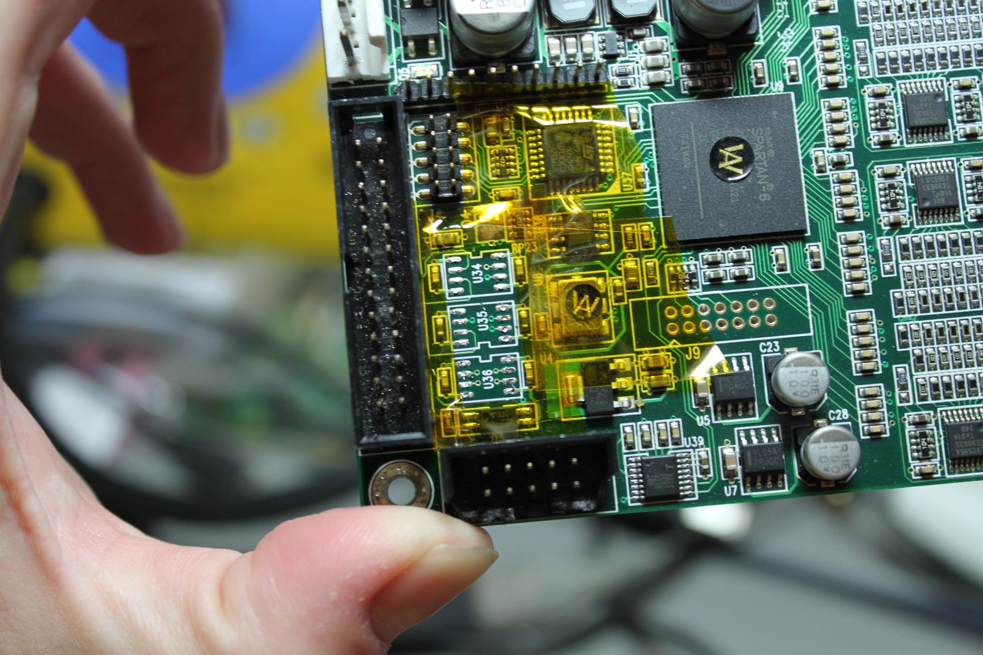
First I had to use Capton tape to cover the “innocent” components close to the isolator chips. The hot air could damage them if I was not careful.
Using the hot air rework station, I desoldered the offending ICs:
And using my normal soldering iron I managed to solder in the replacement ICs:
It may not look as good as the original solder work, but the board is now as good as new. 🙂