This should be interesting..

This should be interesting..
These days I’m co-developing an AK4490 based DAC. The aim is to end up with a no-compromise dual mono design, one that would perform at the very least on par with my Buffalo III.
Of course, to do that one has to run the 4490s in software mode.
As a matter of fact, it is generally preferred to run a 4490 in software versus hardware mode, for several reasons.
To begin with, in software mode the 4490 supports DSD decoding. It goes as far as to support a “Volume Bypass” feature which bypasses most of the processing done on the DSD signal (a.k.a. “the ΔΣ modulator”), resulting in more pure sound. But of course we do lose the ability to do volume control in software.
Software mode also allows us to try out all of the supported SQ features, like the different “Sound Setting” modes.
At last but not least, we get digital hardware volume control.
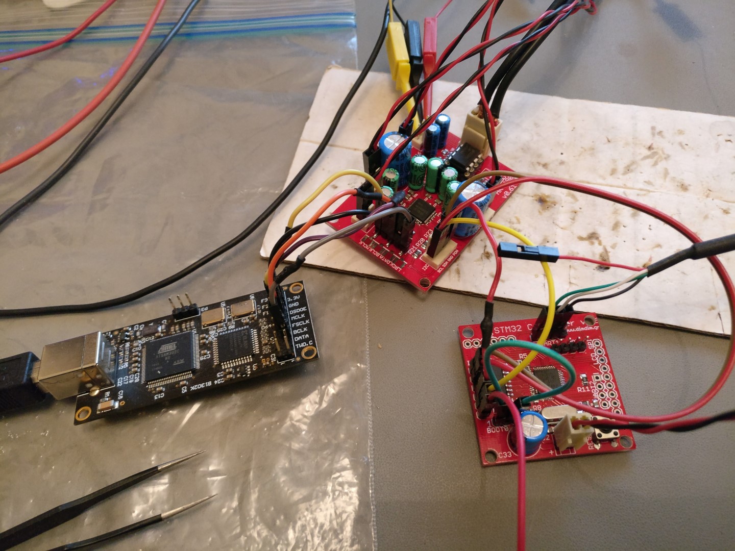
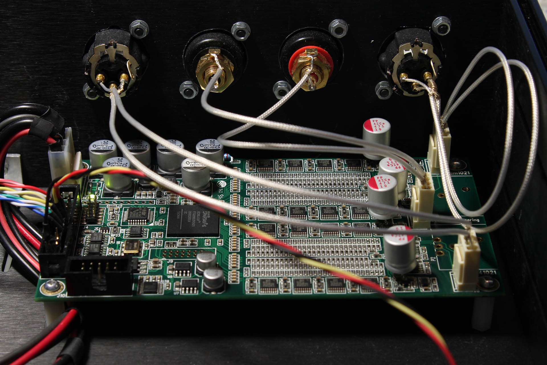
This is the prototype that we designed, getting I2S input from an Amanero and being controlled by my custom STM32 controller (more on that in the near future).
I searched the Net for any ready-made code that would control the 4490, but I couldn’t find anything worthwhile, so I began virtually from scratch.
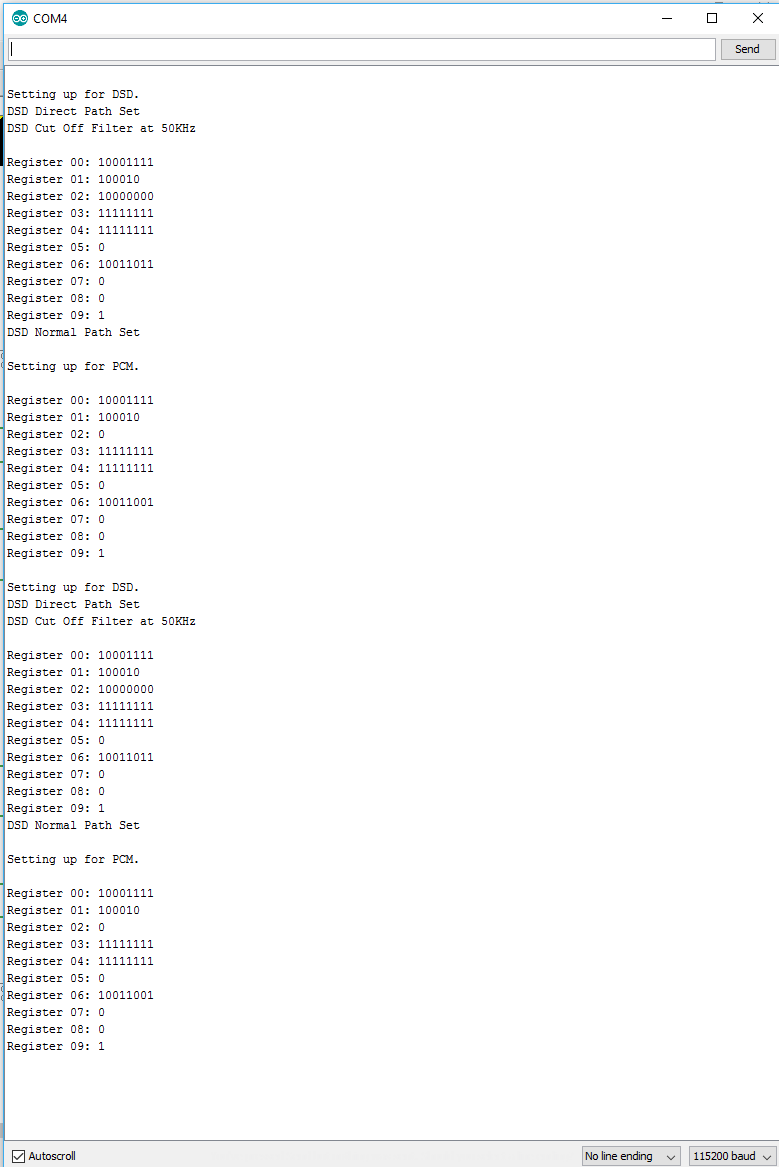
So, my Arduino code (a.k.a. “aKduino”) enables:

Software Requirements:
Basic Hardware Requirements:
(*) I should note here that the AK4490’s datasheet states that all of its I/O pins are expecting 3.3V logic levels but there has been a large number of reported cases of 5V Arduinos working without problems. I’m too much of a coward to try that myself so I used level converters for my initial testing and eventually a custom STM32 board that uses 3.3V logic but you may want to try your luck with 5V logic levels. Just don’t blame me if your 4490 gets damaged in the process.
Currently the code is at v1.35:
Here is the revision history:
v1.35 20/12/2016:
v1.33 19/12/2016:
v1.27 18/12/2016:
Back in August an interesting thread was started on diyaudio.com.
It described a FIFO buffer and reclocker, aimed at SBCs and more specifically the RPi.
Its name was Kali.
The FIFO board would be able to “fix up” the RPi’s problematic I2S output so as to improve the sound quality of the used DAC.
As the discussion progressed, more interesting details came to light.
Kali was basically an FPGA design with on-board RAM, high quality clocks and flip-flops. It would buffer the DATA stream in RAM (about 0.7 seconds of audio) and it would then reclock it using flip-flops outside of the FPGA. The clocks used for the reclocking would be high quality NDK units sporting extremely low phase noise.
It would be powered by a 5V/3A power supply and would supply filtered power to the RPi (or not, selectable by a jumper) as well to the DAC that would sit on top of Kali.
It would have a claimed 3ps of jitter, which is an impressive feat for any I2S source.
It would provide a high quality MCLK output from a U.FL jack underneath the board.
The board’s general availability was scheduled for the end of August, and its price would be in the neighbourhood of $70.
At around mid August cdsgames offered to give away a number of units to diyaudio members for testing. I took him up on his offer and he was kind enough to send me one (along with a Piano 2.1 DAC board, but that’s for another post).
Fast forward to mid-September, when I received a package from India. In it was Kali and Piano 2.1 (more about that in another post).
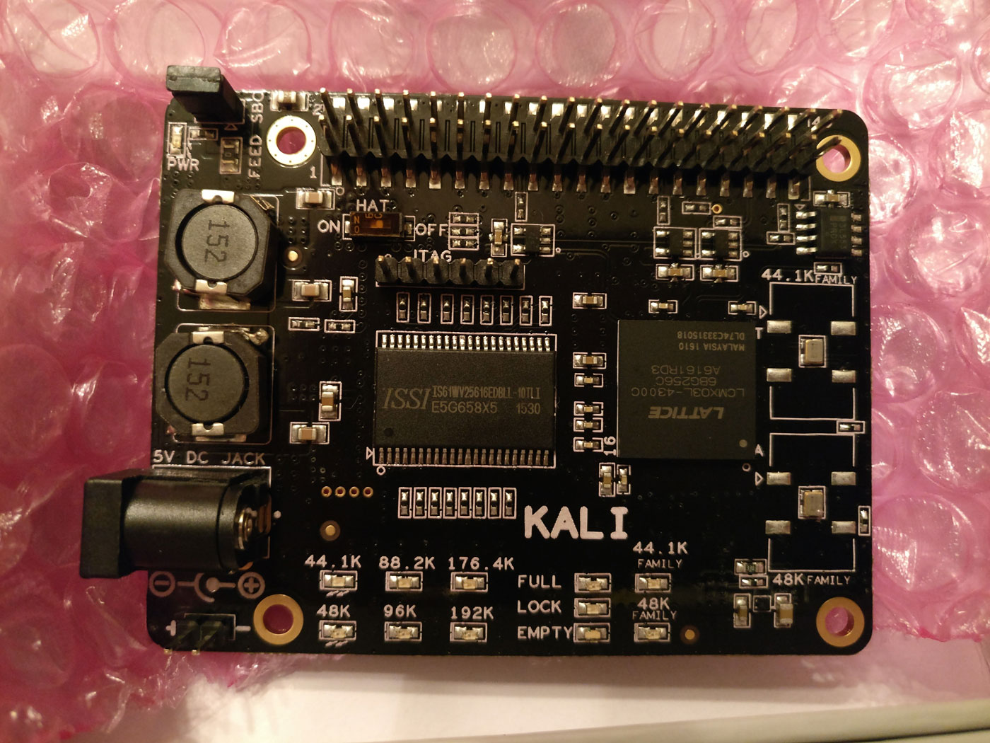
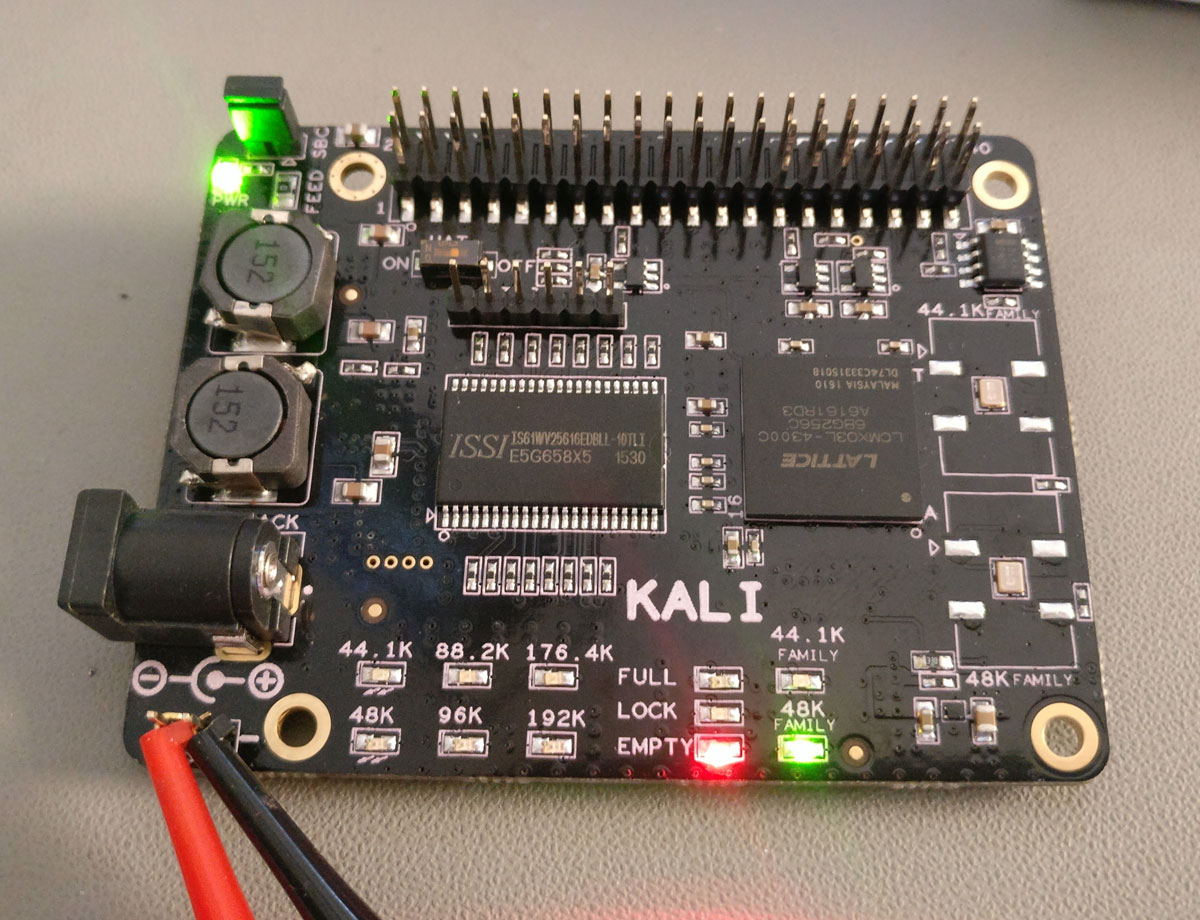
On the left side of the board we can see the DC IN jacks (barrel and pin header), plus a couple of inductors that help with filtering the power lines. On the top left there is a jumper that controls whether Kali will supply power to the RPi or not. The Kali lists as minimum requirement a 5V/3A power supply. However, Kali itself will consume only about 100mA. The rest of the power is intended for the RPi and the DAC board. Note that Kali is designed so that it powers the RPi and not the other way around.
In the middle of the board the two chips that dominate are the 4Mbit SRAM chip and the Lattice MachXO3L-4300 FPGA itself.
To the right we have the two NDK clocks, one for each one of the two “families” of sampling rates.
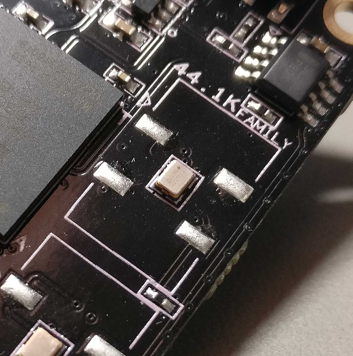
The Kali comes in two versions. One with clocks at 22/24MHz, capable of supporting sampling rates up to 192KHz, and one with 44/48MHz clocks, going up to 384KHz.
Note that there are two footprints available for the clocks so that a curious (and somewhat experienced) DIYer can also try out clocks with different footprints, like for example Crystek units. If you choose to go that way, keep in mind that you will also need to change 2 capacitors from 0.01uF to 0.1uF.
At the top of the board we have the usual 2×20 header that reproduces the RPi’s GPIO pins. There is one notable exception – Kali does not supply 3.3V at the relevant pin, so if your DAC needs to take 3.3V from that pin it will not work (more on that later).
Note that even though Kali has a JTAG header, the manufacturer currently does not support firmware upgrades. That’s understandable.. JTAG is not for consumer use and the manufacturer has to protect his IP..
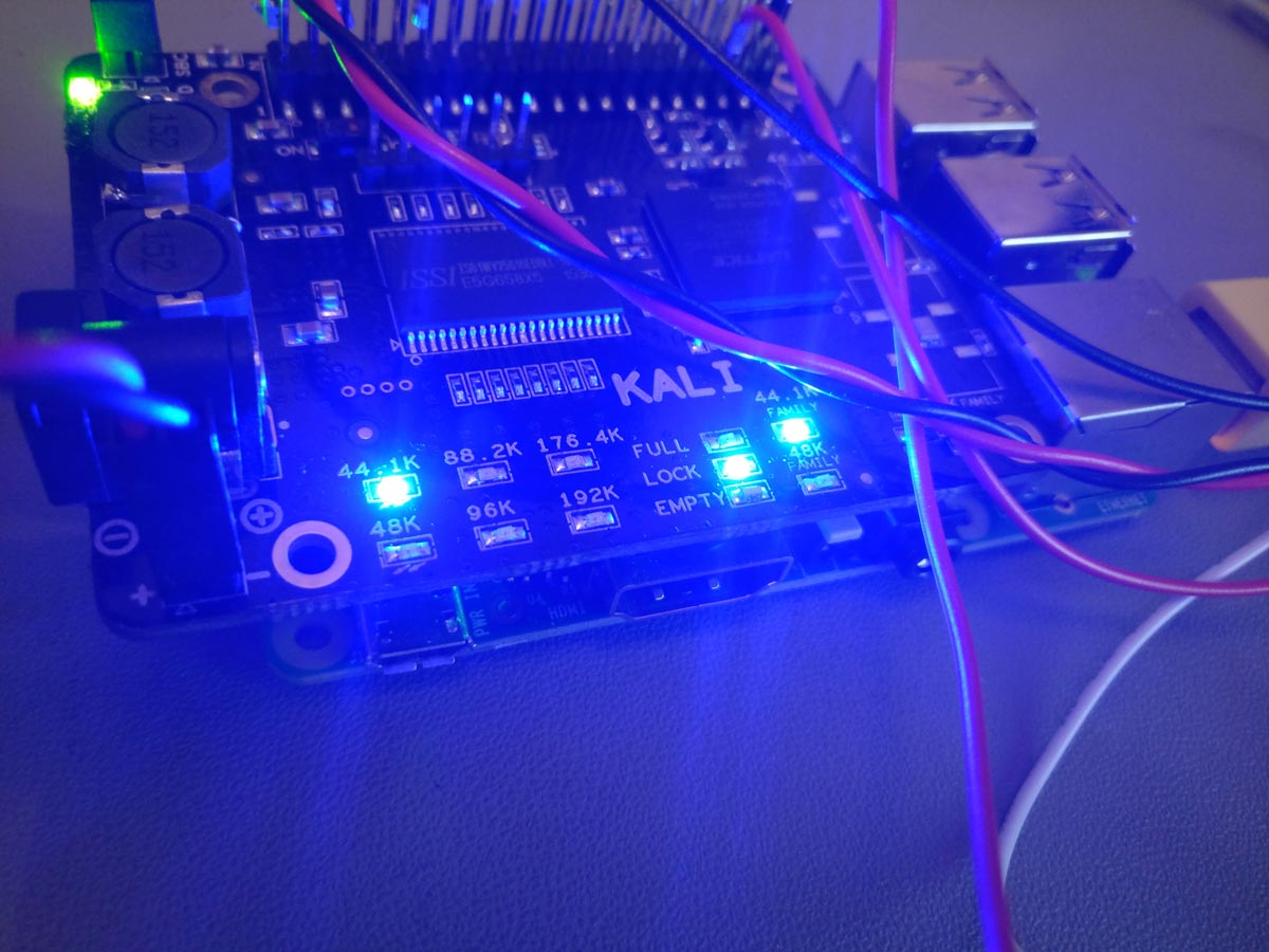
At the lower end of the board we have an array of LEDs indicating the sampling rate of the incoming signal, along with the status of the buffer (Empty / Full / Lock) and the selected oscillator.
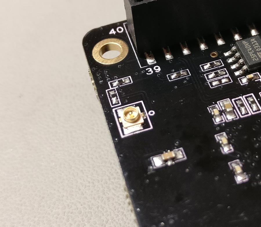
At the bottom of the board there is a U.FL socket that outputs Kali’s MCLK.
So, we have an RPi, we have Kali, now what we need is a DAC. Kali will put a few restrictions on your DAC choices. Your DAC will have to run as “slave” to the RPi, that is it will have to take its BCLK from the RPi and not the other way around. Examples of such DACs include for example virtually all of the DACs based on ES9023 chips. DACs that are designed to run as masters (in order to battle the RPi’s legendary jitter problem), such as the Hifiberry Dac+ Pro & Digi+ will not work, at least not without some extra work.
Plus, like I mentioned earlier, Kali does not supply 3.3V on its top 40-pin header, so if your DAC requires that voltage you’ll need to find a way to supply it externally.
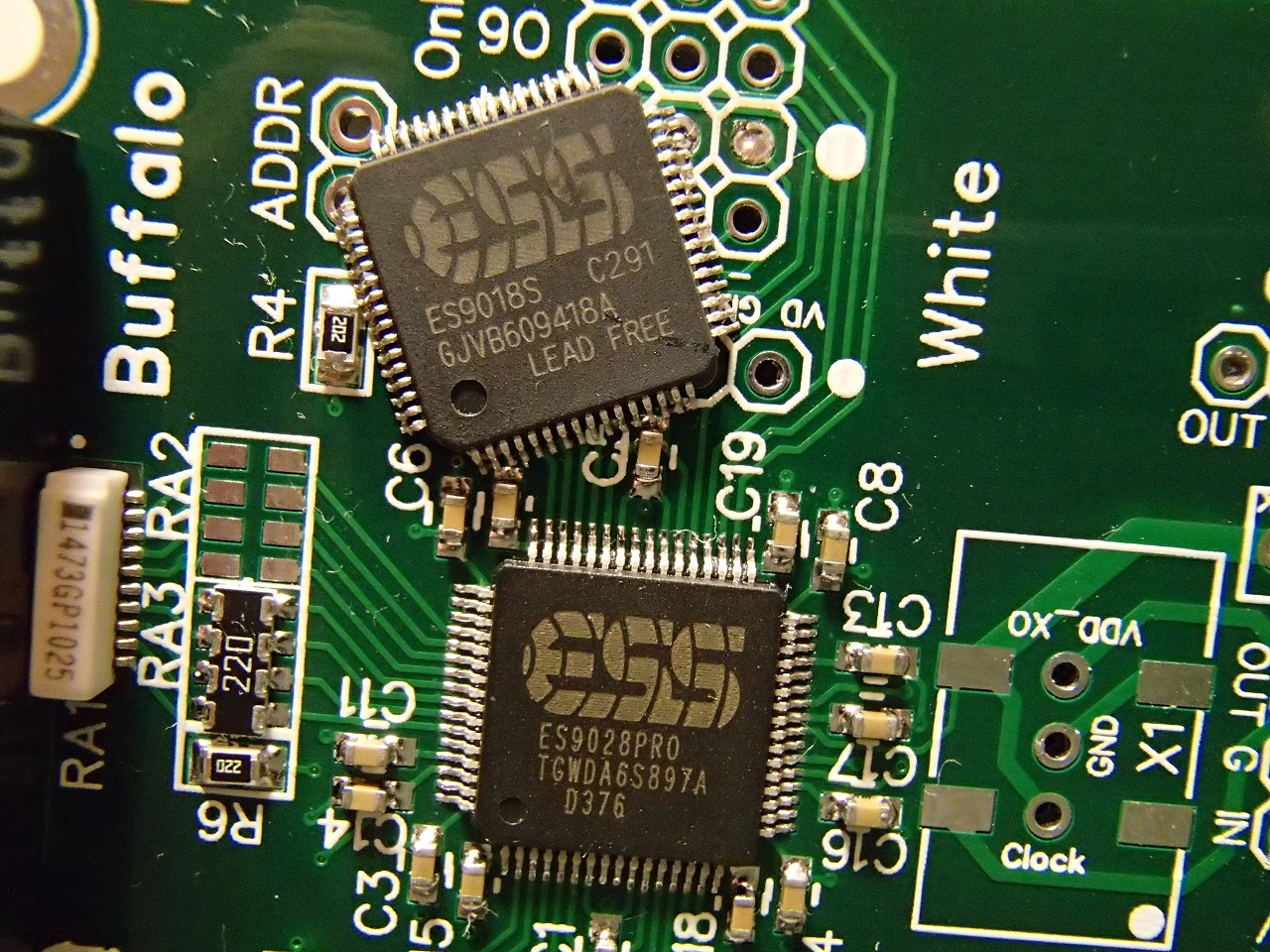
Straying a bit from the DAC HATs, Kali will have no problem feeding pretty much any DAC that accepts standard I2S, like for example a TPA Buffalo DAC.
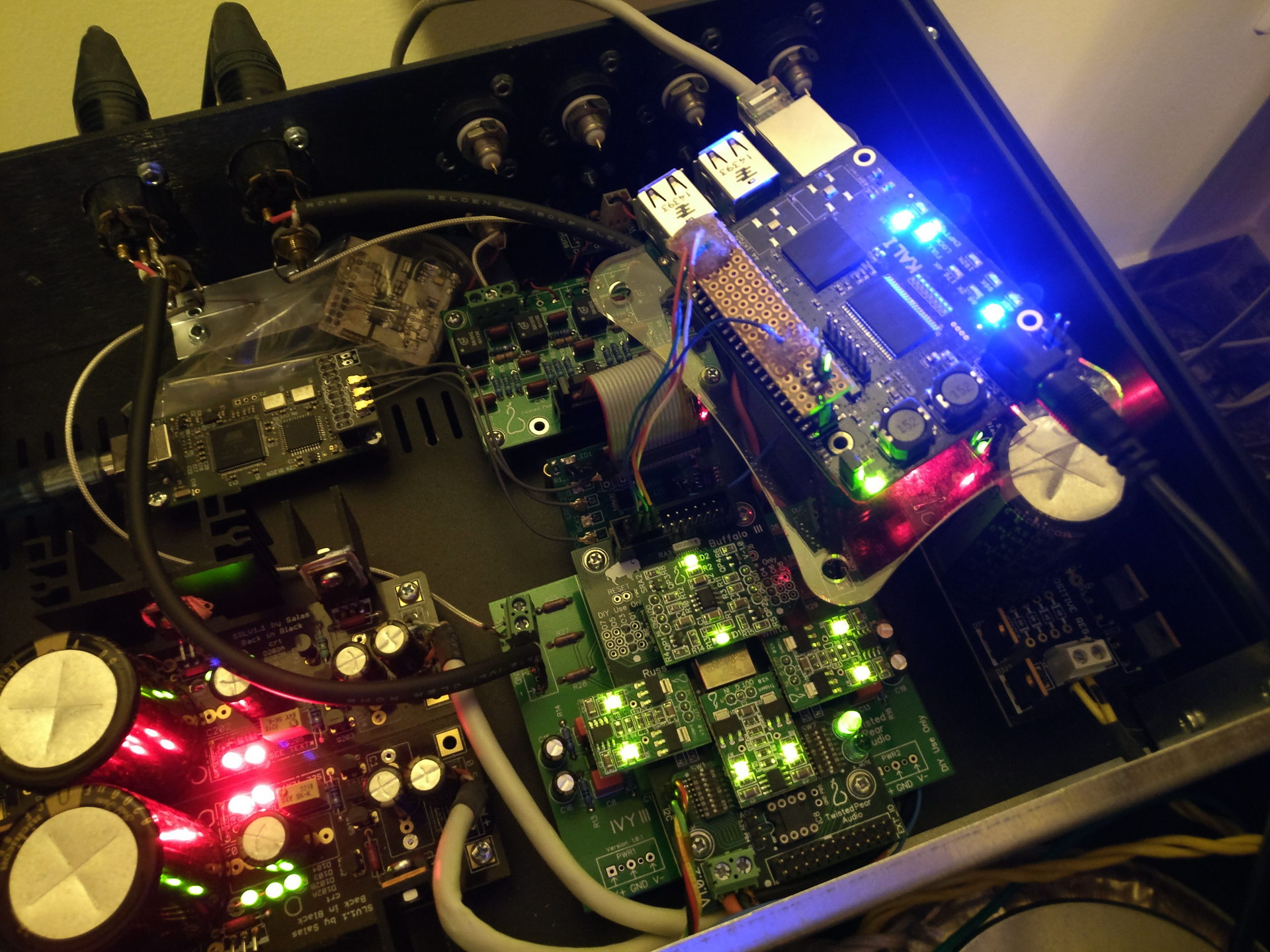
As a matter of fact, in my system Kali did a remarkable job of improving my RPi’s I2S output. The difference was obvious immediately. My RPi went from being a “net streamer quality” source to giving my Amanero a run for its money. Remarkable.
I am not talking about differences in bass or treble or tonality. It is like Kali manages to extract more music content from the data files. It revealed details that were there but were not audible. The music became more “real”. Imagine going from SD TV to HDTV. And that with the same 44.1K/16bit source material.
This improvement is not apparent only on expensive gear either. My first tests were done on my workbench with my RPi feeding an $8 9023-based DAC and listening through my headphones.
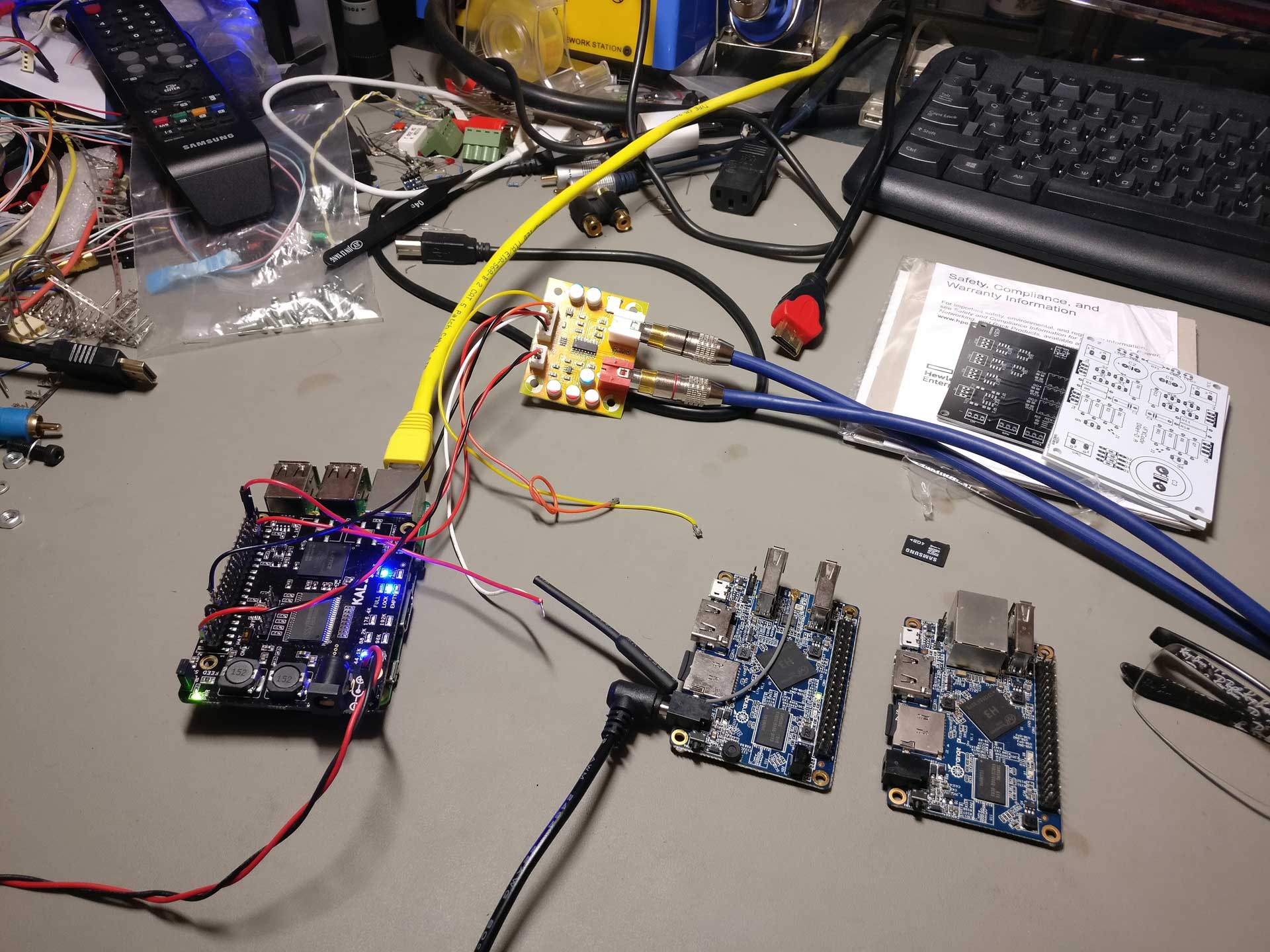
Even with this setup, Kali made a significant improvement to the sound. The $8 DAC went from sounding like an $8 DAC to performing at least decently. It was an obvious improvement.
So I can not imagine a scenario in which the Kali will not make an audible improvement to the sound.
Note that the first batch of Kalis (the ones that were sent to reviewers and a small number of units that were actually sold) had a bug that caused 16bit audio to have its channels reversed (and some more weird stuff happening with their I2S output resulting in somewhat degraded sound quality), but according to allo.com all effected units have been exchanged with fixed ones plus the ones that are shipping now to customers come with a fixed version of the firmware.
Even if for some reason you come by an affected unit, all you have to do is tell your RPi to output 32bit audio. That will fix everything.
I’d like to thank Ioan (cdsgames at diyaudio.com) for sending me the remarkable Kali. It will for sure become a permanent part of my audio chain.
At the time of this writing, Kali is being sold directly from its manufacturer’s site (allo.com) as well as from Volumio’s online shop.
A new page is up: https://www.dimdim.gr/diyaudio/la-skala-attenuator/
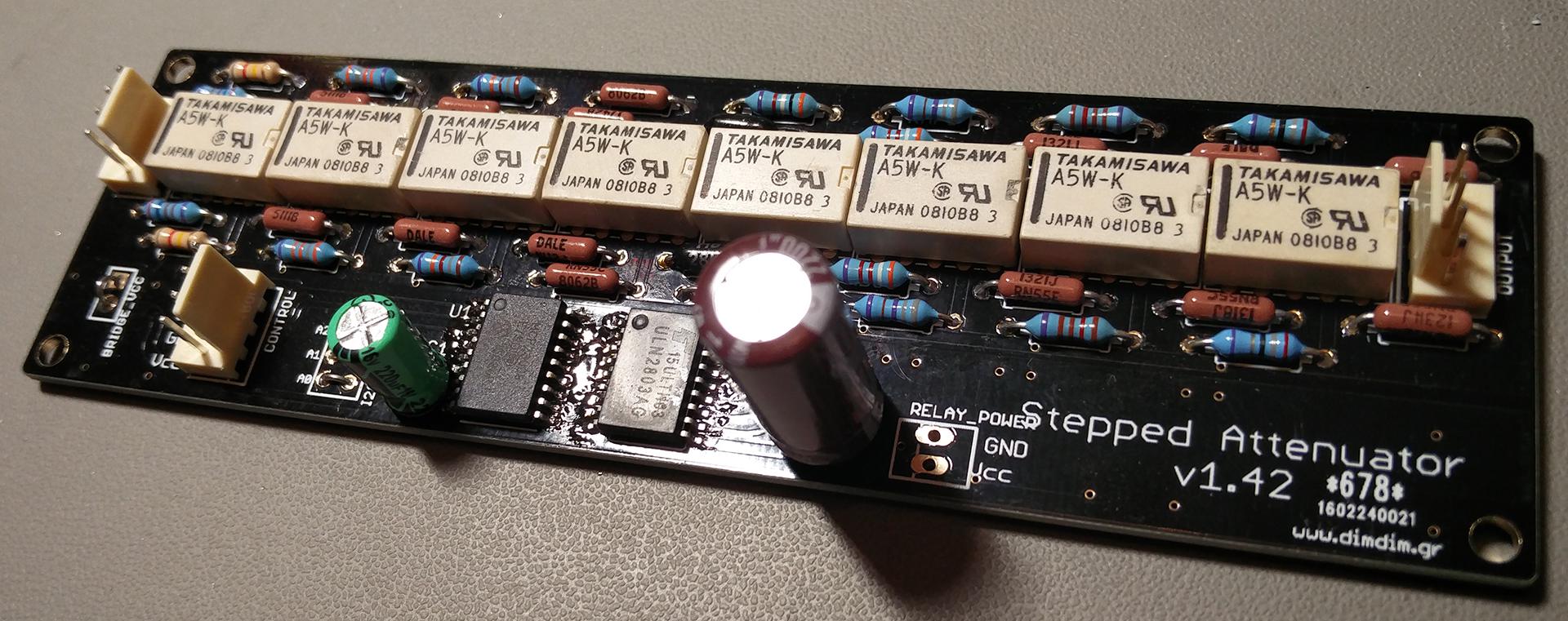
It is my take on a stepped ladder attenuator, controlled by an Arduino.
After too many years of abstinence from headphones, I was given as a present a pair of Fostex T50RP MK3s.
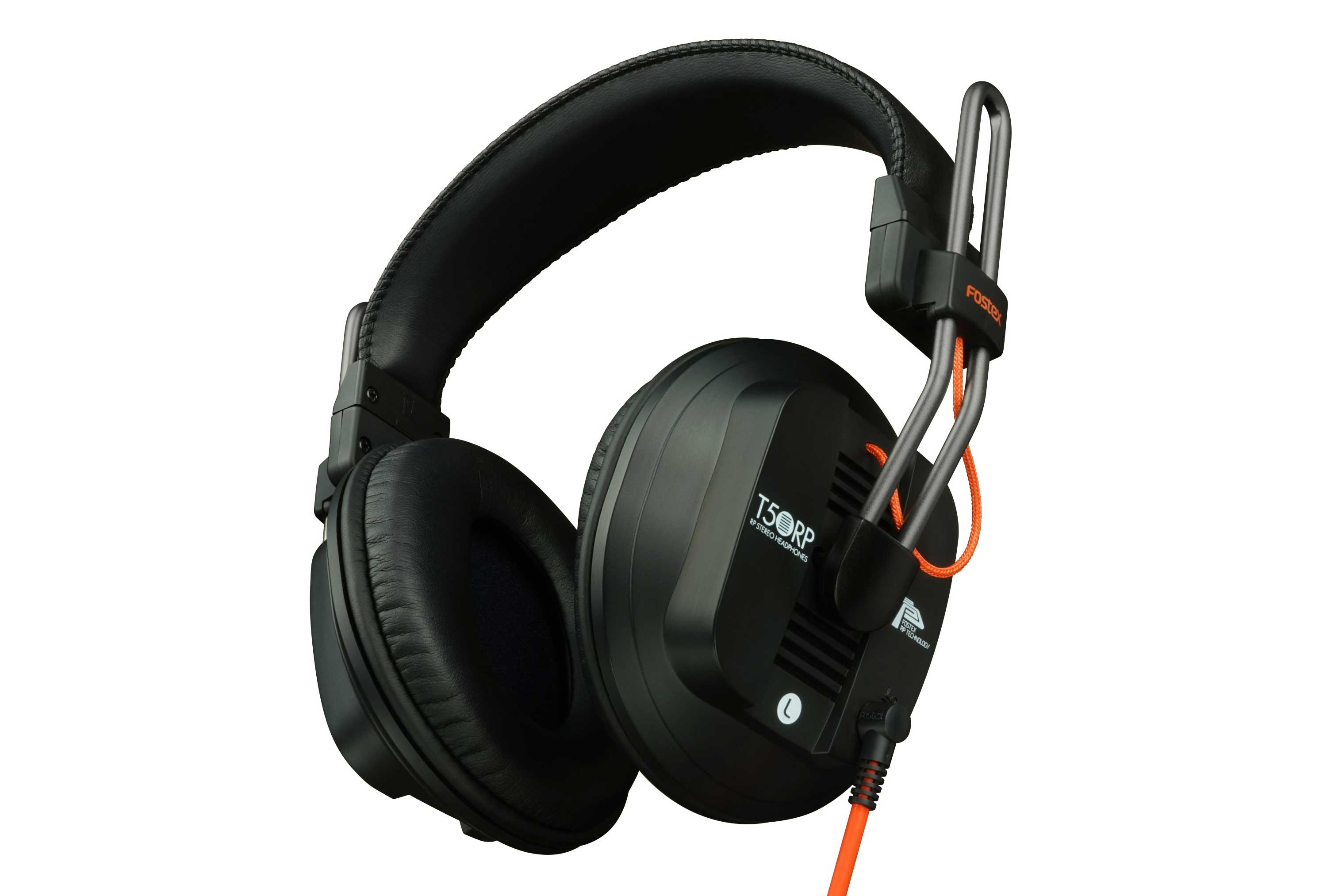
These headphones have an excellent VFM, having true planar magnetic drivers at a price point of ~150€.
This is what they look like on the inside:
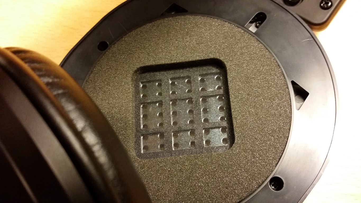
Picture borrowed from here: http://www.head-fi.org/t/763009/fostex-new-rp-headphones-t50rpmk3-t40rpmk3-and-t20rpmk3/375#post_12077324
There is a drawback though, and that is their low sensitivity. ~92dbs mean that my current cell phone has no hope of making them rock. No chance at all. Same goes for pretty much any USB-powered DAC/headphone amp. So anyone serious about driving these headphones needs to look into a proper headphone amplifier.
I said to myself that I should try to build a proper amp with parts that I already had lying around, so I looked at my stockpile. I realized that I had a brand new pair of AMB alpha20 class-a line amplifiers, rated at 3.0Wrms into 33Ω with a ±18VDC power supply.
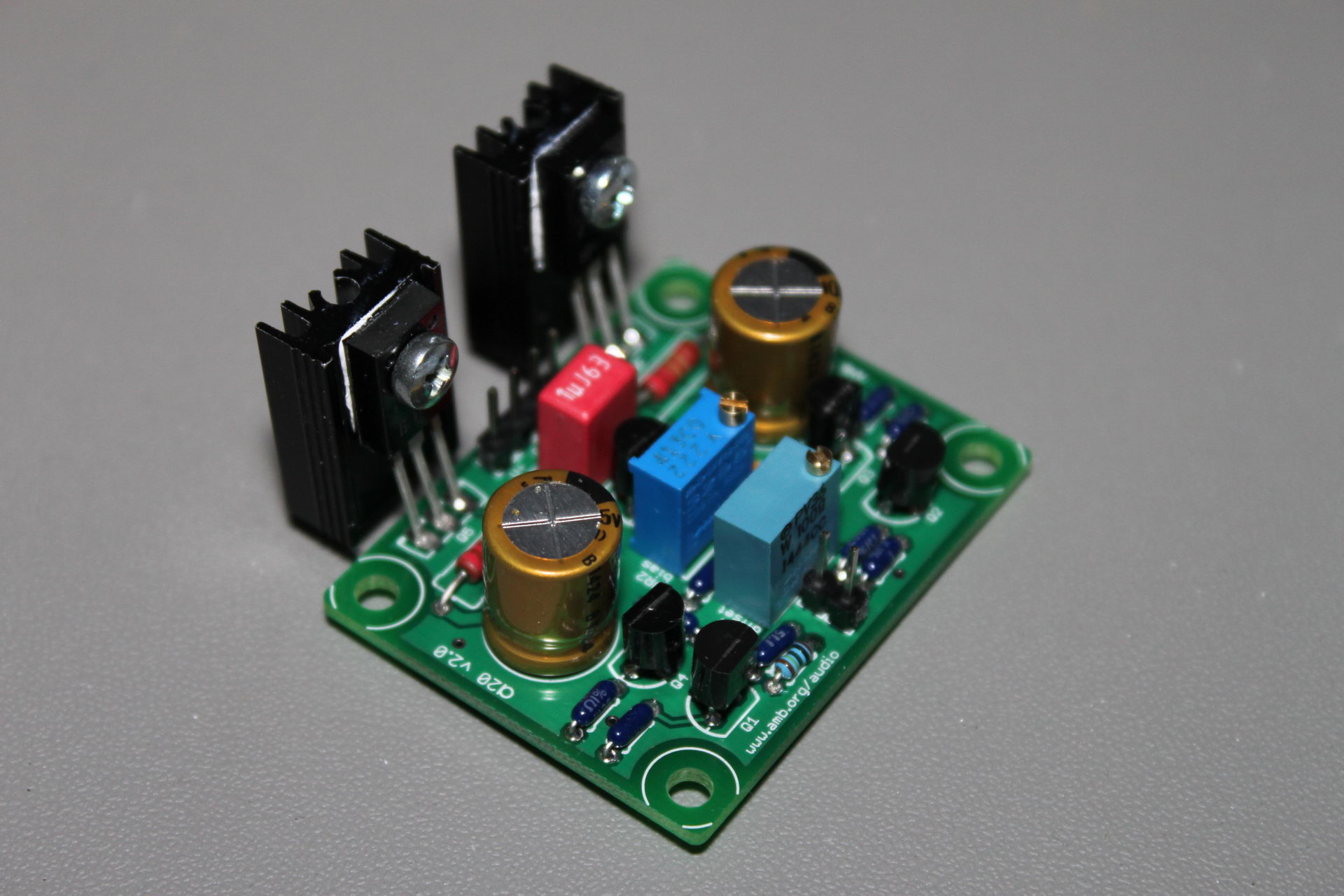
The T50RP are 50Ω and can handle up to 3000mW, so I thought that they would be a good match.
Powering the alphas by my bench power supply, I connected them to my audio card’s line out (an Auzen X-Meridian) and hooked up the headphones. The result was impressive. The alphas delived sound that was clear, crisp, with very little distortion. Plus they managed to achieve SPLs well into eardrum-damaging territory. Good.
Next up was the power supply. I had a set of Salas BiB shunt regulators that were collecting dust, so they would do just fine.
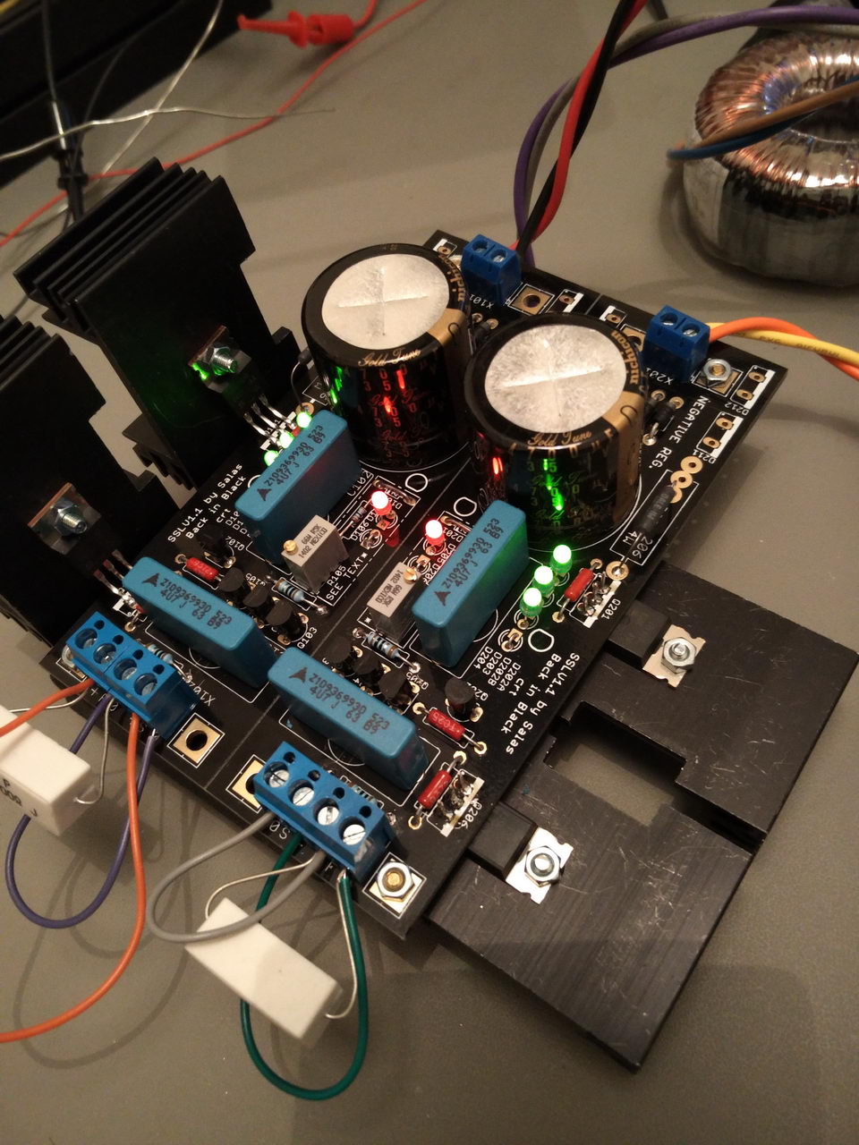
I set them up for a CCS current of ~300mA.
The case would be a Modushop.biz Galaxy 1U aluminum one that I had bought for a project that never went beyond the design phase.
I was missing a transformer that would fit inside the 1U case, so I bought a 25VA unit from Mouser.
At last but not least, I needed a 1/4″ TRS jack that could be mounted on a 10mm thick aluminum face. Neutrik had the perfect part for the job:
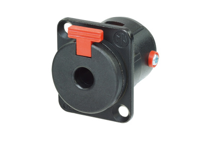
So, all I ended up purchasing was the trafo and the 1/4″ jack. Nice.
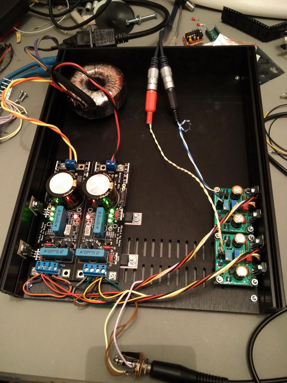
So now I had a functioning headphone amplifier.
The next step is to add a USB to I2S interface, a DAC, some sort of volume control, another power supply to power them and an Arduino & Screen to control them. Space might be an issue..
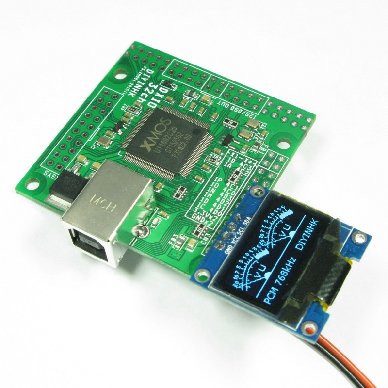
About a month ago DIYINHK released a USB to I2S interface board based on the brand new and all-powerful XMOS xCORE-200 chip.
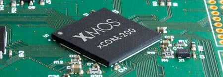
![cXU216[1]](https://www.dimdim.gr/wp-content/uploads/2016/01/cXU2161.png)
The specific chip used by DIYINHK is the middle-of-the-line XU216-512 which corresponds to some pretty serious horsepower: 16 logical cores for a total of 2000 MIPS, 512KB SRAM, 2MB FLASH.
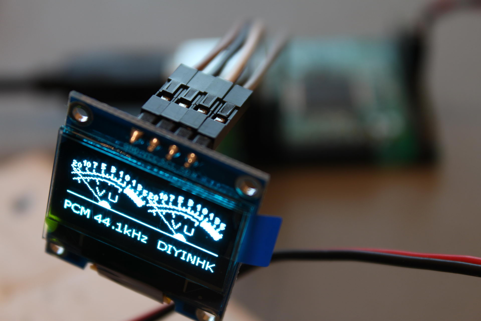
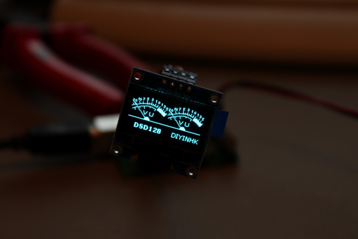
So, what can we do with all this horsepower you say? It’s simple. Tons of channels of high-resolution audio. Plus I2S inputs, besides the usual outputs. Plus DSD1024. Plus use a cool OLED display as a VU meter.
The board I bought came with the default firmware, which supports:
Here is a video of it in action:
A maximum 32 channels can be supported with the right firmware (not provided by DIYINHK).
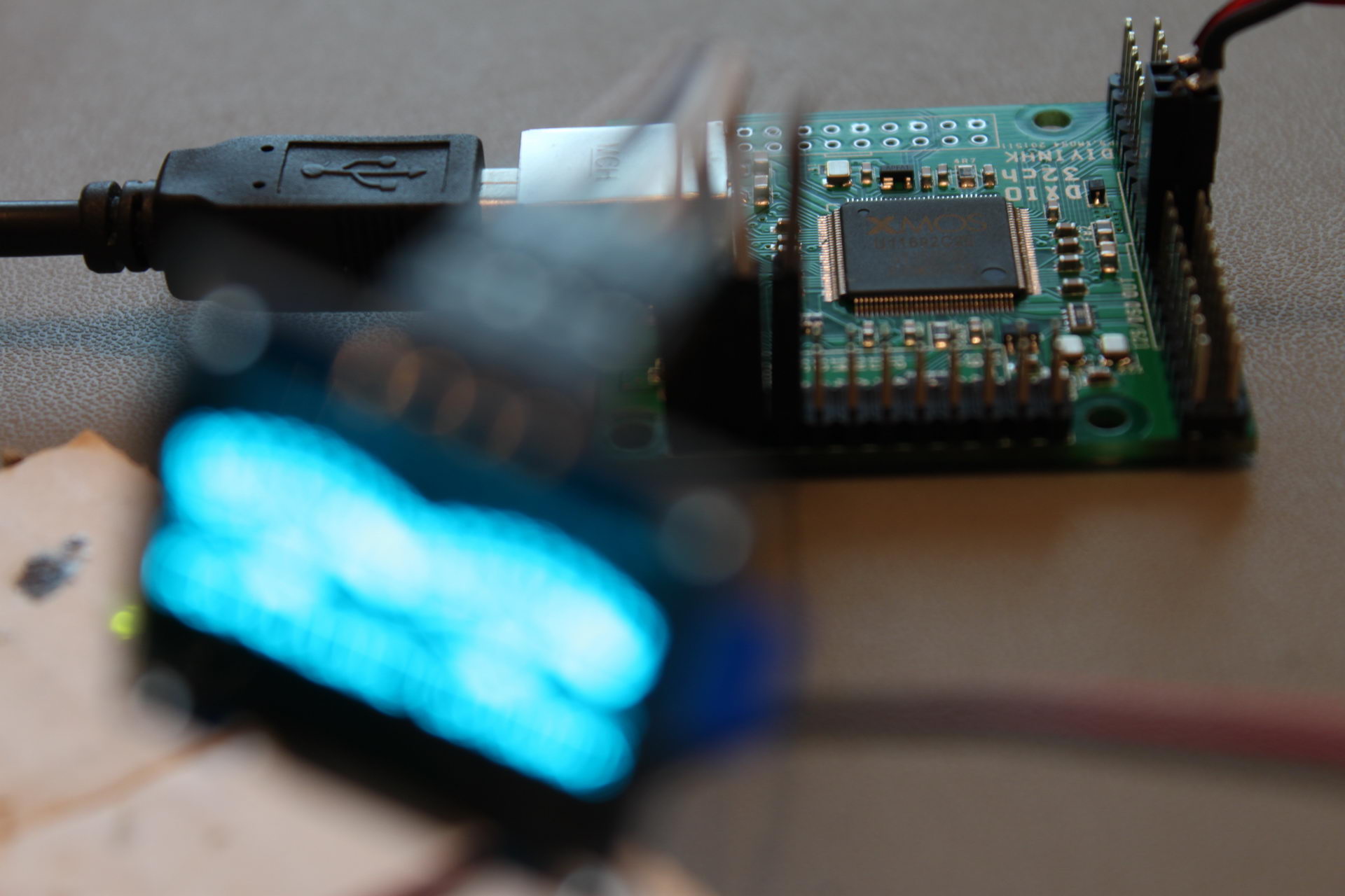
The board (a 4-layer design, btw) comes with three high quality NDK NZ2520SD Ultra low phase noise oscillators. There is provision for powering two of the oscillators externally, by removing a ferrite bead and applying power through one of the headers.
The board is not USB powered. It needs a relatively beefy 3.3V power supply, capable of providing a maximum of 800mA (even though a typical power consumption is in the neighborhood of 570mA). Beware, a weak power supply or an inadequate connector will cause to board to not power up.
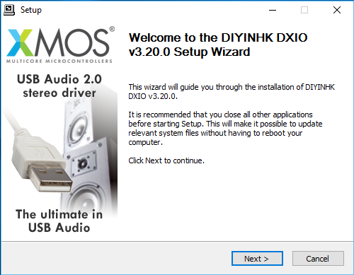
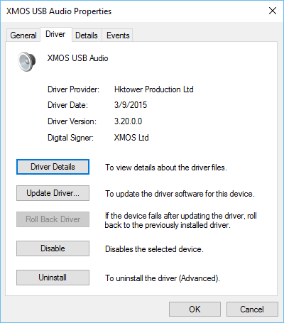
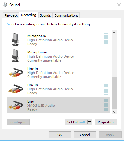
It comes with a fully featured Thesycon driver for Windows. Linux & Mac OS don’t need a driver.
An interesting detail is that the Windows 10 driver that is available only supports stereo operation and no multichannel (v2.26). If you want multichannel you’ll have to go back to Windows 7 (v1.67) (or perhaps Linux or Mac OS, it isn’t clear..).
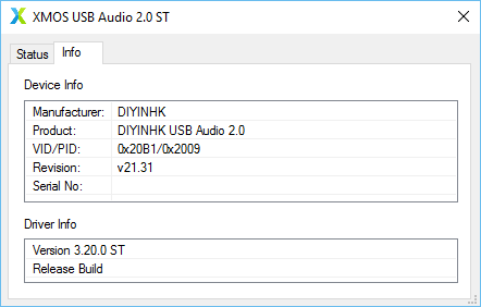
DIYINHK’s site says that the latest available driver is v2.26, but I did not find such a driver in their downloads section, so I emailed them about it. They sent me a link for an even newer driver, v3.20.
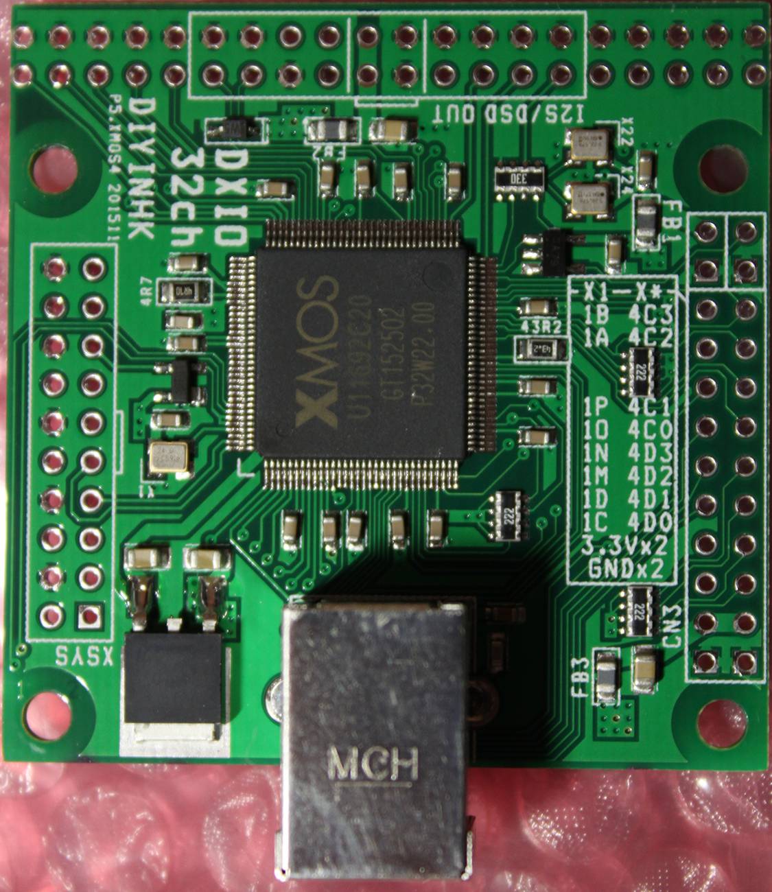
The board has a ton of exposed I/O, split into three 0.1″ headers. These are the pinouts, according to DIYINHK:
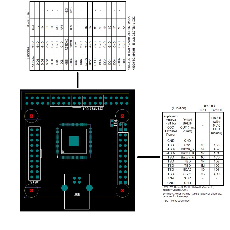
Now, if these pinouts look somewhat cryptic to you, you are not alone. I will try to clarify things a bit.
This is the most interesting header:
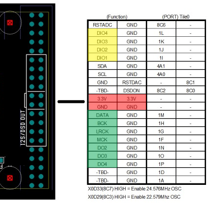
I have marked in red the power supply input. It is a good idea to use all of the pins for making the connections, since ~800mA is nothing to sneeze at.
The pins in green are the I2S outputs. For 2 channel operation you will need to connect the DATA, BCK & LRCK pins. The rest of the output channels should be available at pins DO2, DO3 and DO4. I say “should” because I haven’t tested them. I should repeat that multichannel operation with the provided driver is only possible at the moment with Windows 7 (and possibly Linux & Mac OS).
The pins in yellow are the I2S DATA inputs. For 2 channel operation you will need to connect the DIO1, BCK & LRCK pins. The rest of the input channels should be pins DIO2, DIO3 and DIO4. The same multichannel restrictions I mentioned above apply to the I2S inputs.
The OLED screen is connected to one of the side headers, like this:
The left header is the XSYS connector for uploading firmware to the XMOS.
Next up: connecting it to my PCM4222 EVM ADC board.
I made a little s/pdif input board for my Soekris:
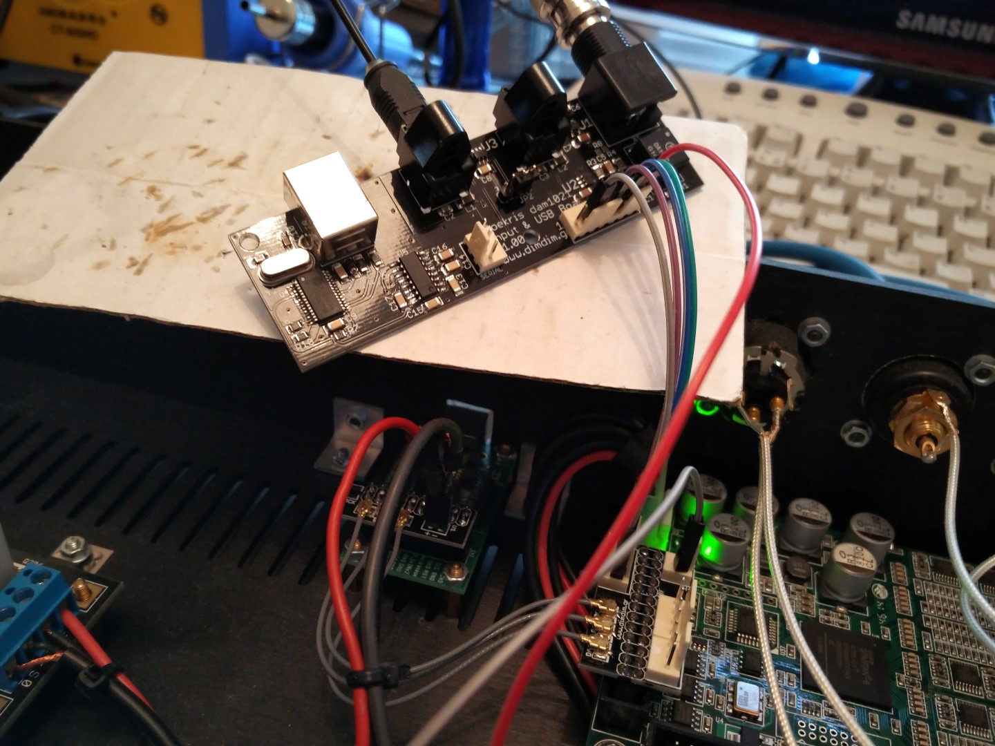
It has a coax input, two Toslink, and it includes a USB-to-serial adapter so as to facilitate easy update of the DAM’s firmware.
It also has an on-board low noise LDO for the Toslink modules and their switch, plus one more LDO for supplying the 1.2V necessary for the coax port.
More info to follow..
I built a solid-state alternative to the TPA’s Sidecar.
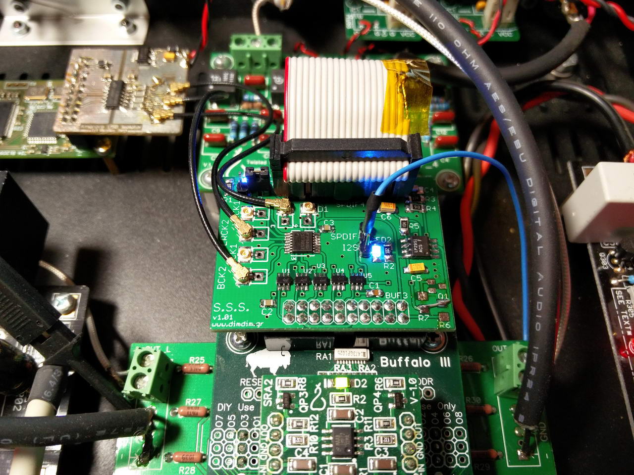
Its main features are:
Schematic, PCB, etc. in its dedicated page: Super Solid-state Sidecar for Buffalo III
It took me a while to get to it, but I finally managed to perform the Vref mod on my Soekris.
I opted for a variation on the “factory mod” with larger organic polymer capacitors.
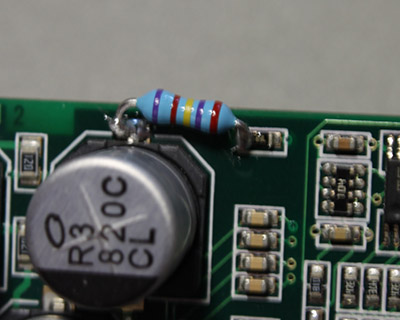
But before I get to the actual modding, I’d like you to take a minute to appreciate just how small a 0603 part really is. This is a 0603 resistor compared to a regular 1/4W resisitor. It is that small.
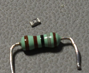
I would not recommend to anyone to attempt this mod without some form of magnification. I used a run-of-the-mill magnifying glass with good results, but it would have been nicer (on my eyes) if I had a proper microscope.
Also, it is crucial to have a soldering iron with a very fine tip, and by very fine I mean needle point. I use an Antex CS18 with a 0.12mm tip.
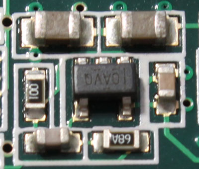
So, let’s get started. This is one of the “stock” Vref regulators:
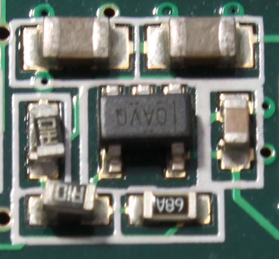
We plan on soldering these 0.1R resistors on top of the existing parts:
You should start by putting a little soldering paste on the existing solder joints. Do not skip this step – it will make your job a lot easier.
Then add some solder on one of the two joints of the existing part so as to tin it. Then place the new part on top of the existing part and heat the tinned joint while holding the new part in place with some forceps. I usually just press lightly on top of it to keep it in place. Use needle-point forceps.
Upon heating, the solder should melt and stick to the new part as well. Then go to the other side of the part and solder it.
Once the new part is secured in place I usually go back to the first joint and add some more solder, just to be sure.
Repeat this for all 8 resistors.
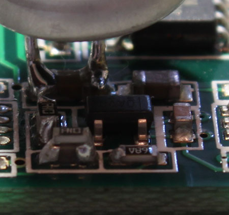
Then it was time to soldered on the capacitors. I had decided to go with the Nichicon NS 470μF / 10V parts. They sport 10mΩ ESR which is perfectly adequate.
I bent one of their leads so that it came closer to the other one, so close that the distance between them was exactly the length of the X5R capacitor they were meant to be soldered on. I then cut them to the proper length (a.k.a. as short as possible). I proceeded to tin both of their leads and then soldered them on top of the existing capacitors. It was a lot easier than soldering the 0603 resistors.
When I was done the Vref regulators looked like this:
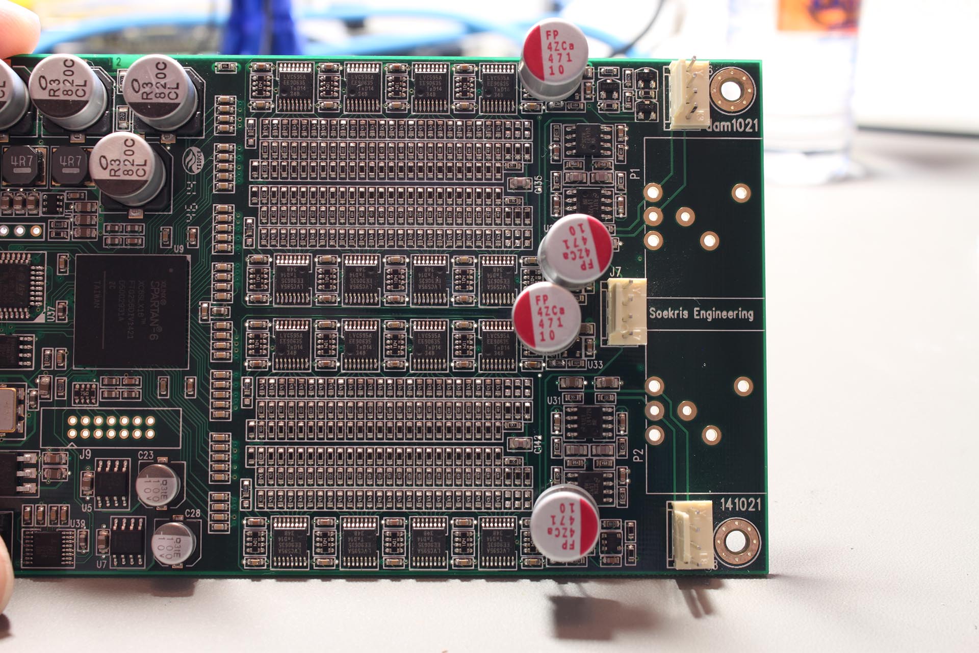
And the entire board now had the well-known “modded” look:
Since I had the board out and the soldering iron hot, I figured I would also do the “power thump” mod, by soldering a 27.1K resistor to the points designated by Soren:
The entire procedure took me a little over an hour.
Now I have to have a listen to see what’s changed..
My Universal Signal Isolator shield now has its own page, complete with the board’s schematic and PCB.
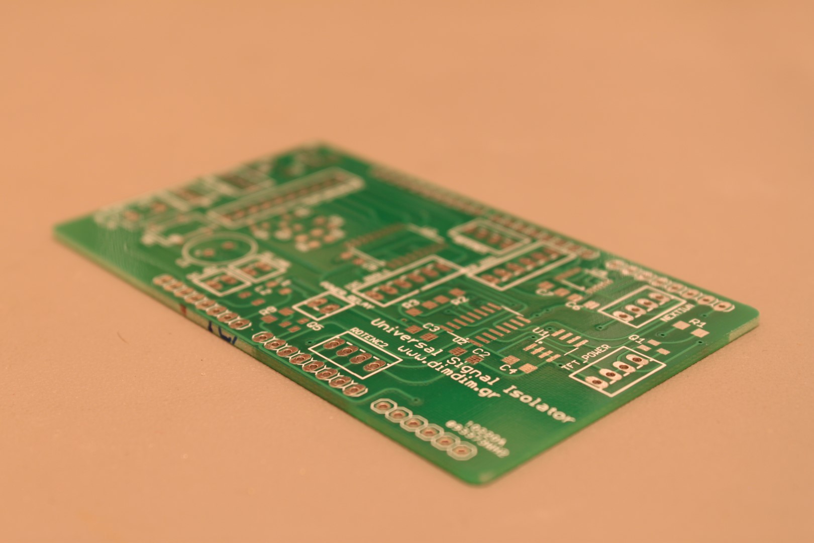
I have tried to document the shield as best I could but feel free to comment if you see something that is not clear or is missing.