Following up on Part 2, it’s time to talk about the output stage.
This output stage is the brainchild of my friend Kostas, all I did was lay out the PCB.
It is a fully discreet single-ended class-A output stage, outputting ~2.4V RMS.
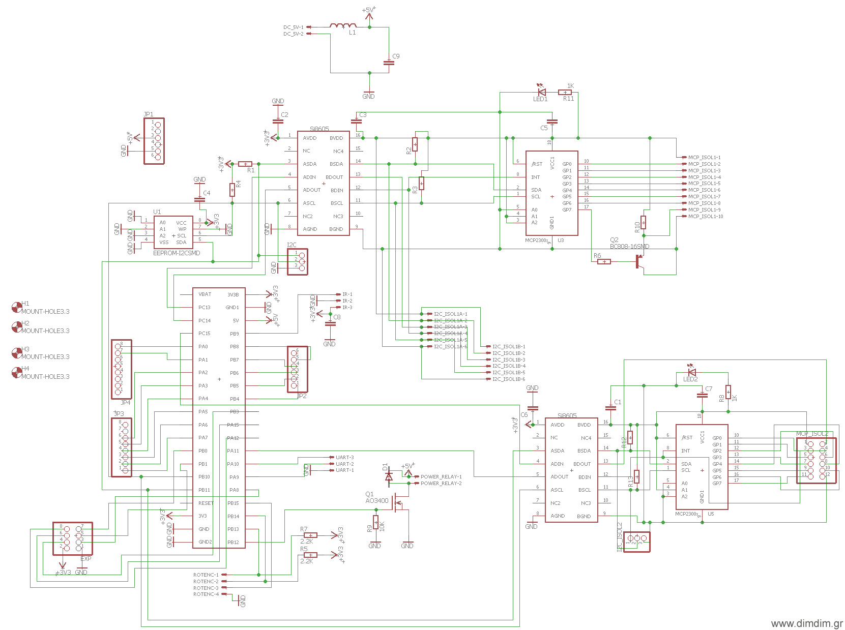
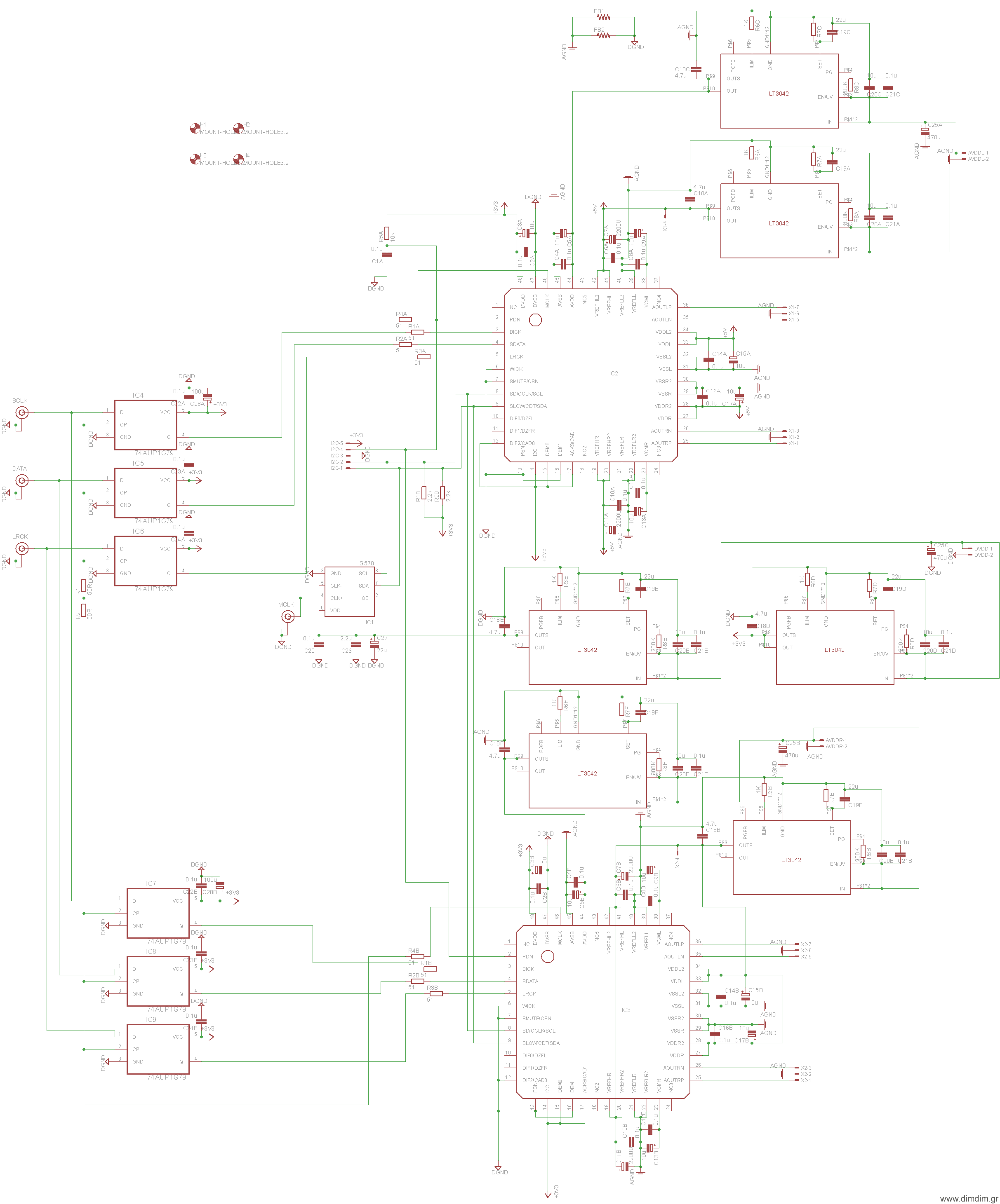
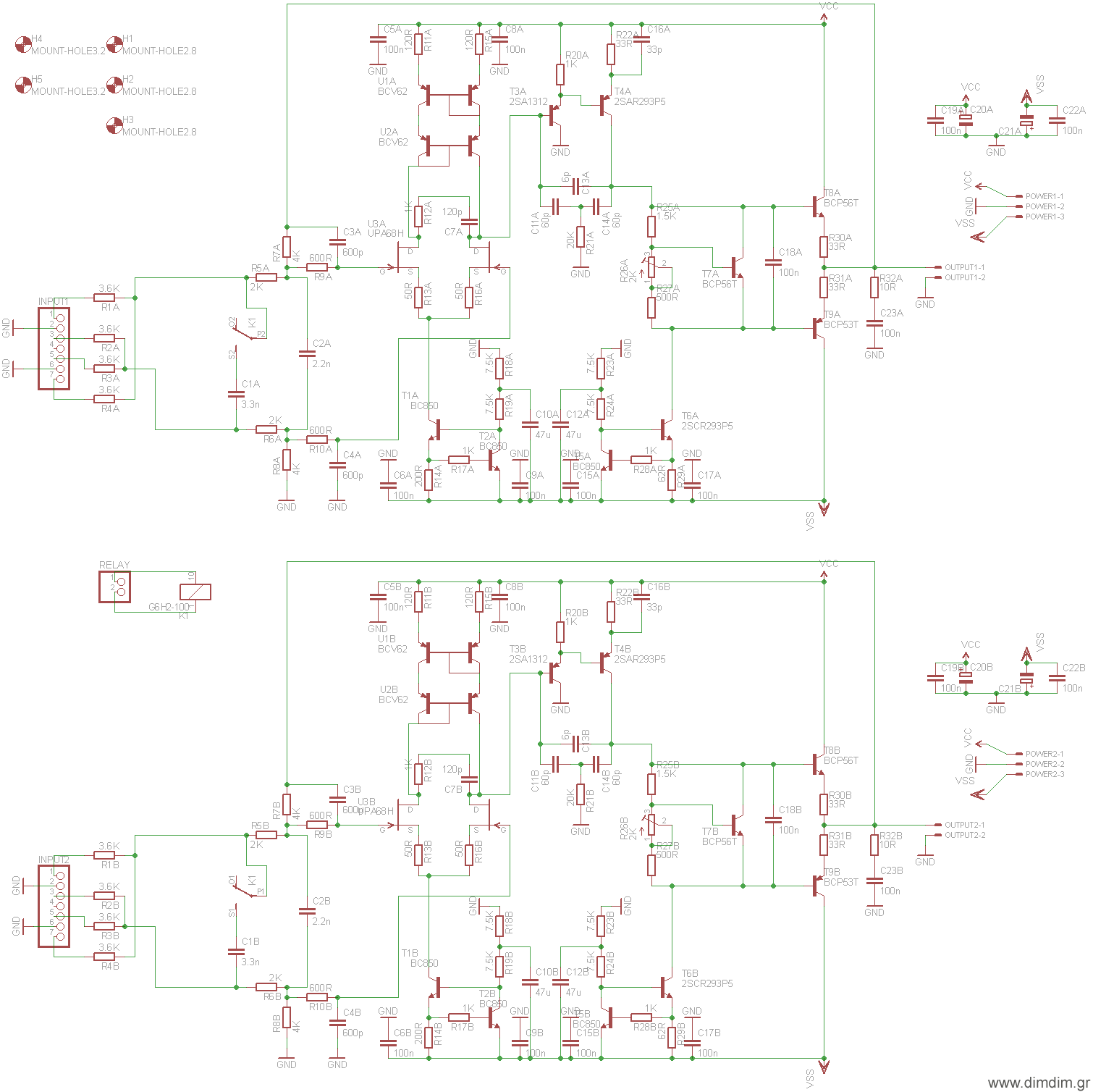
This is its schematic:
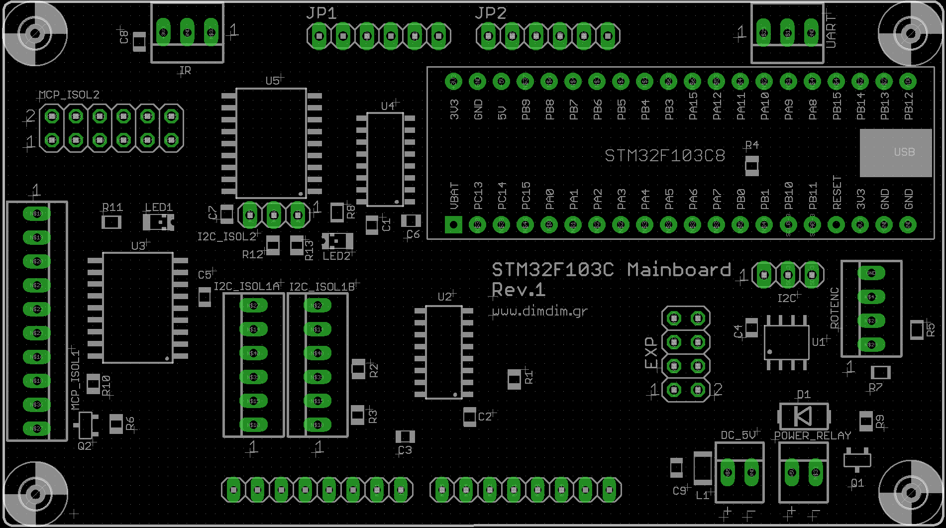
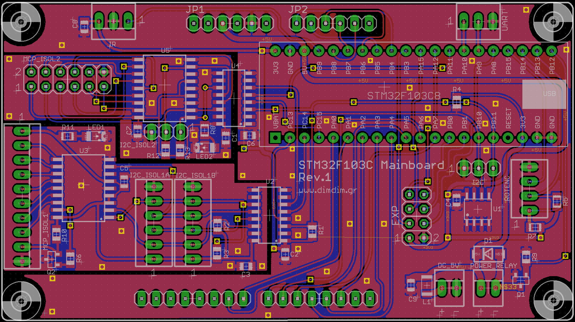
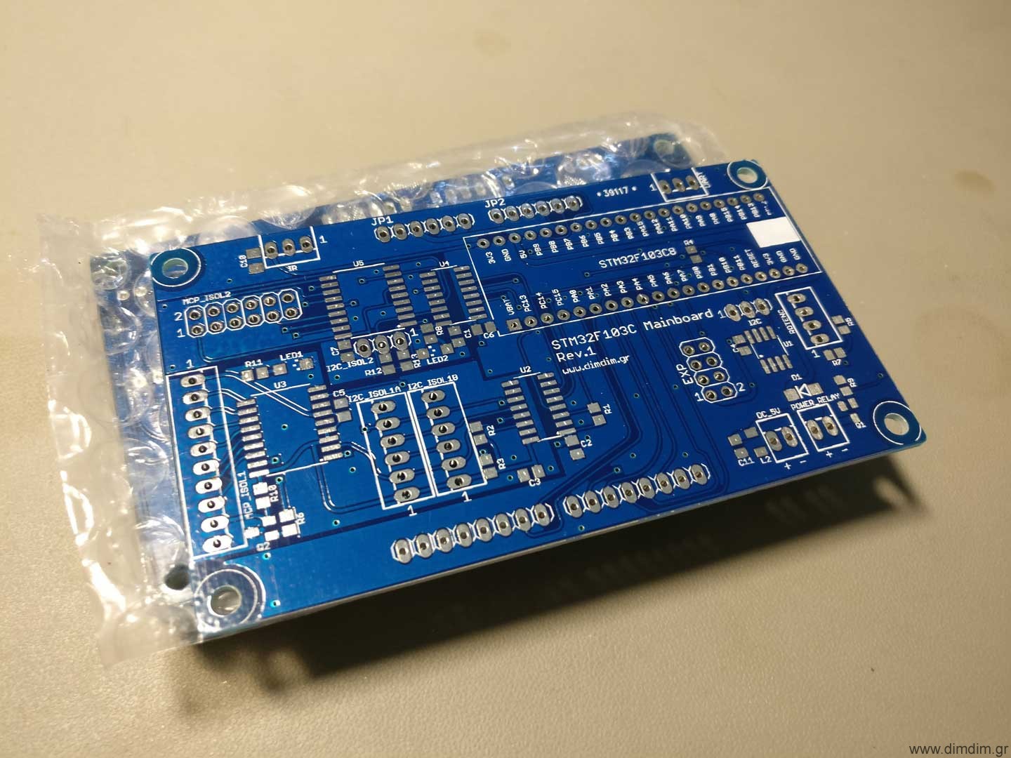
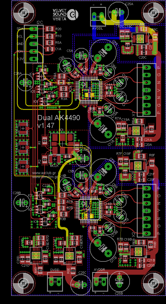
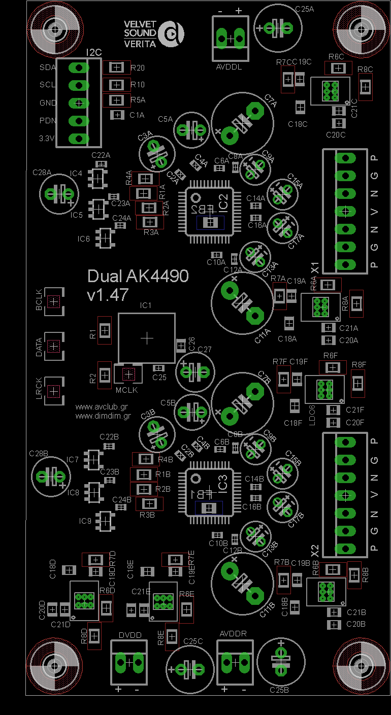
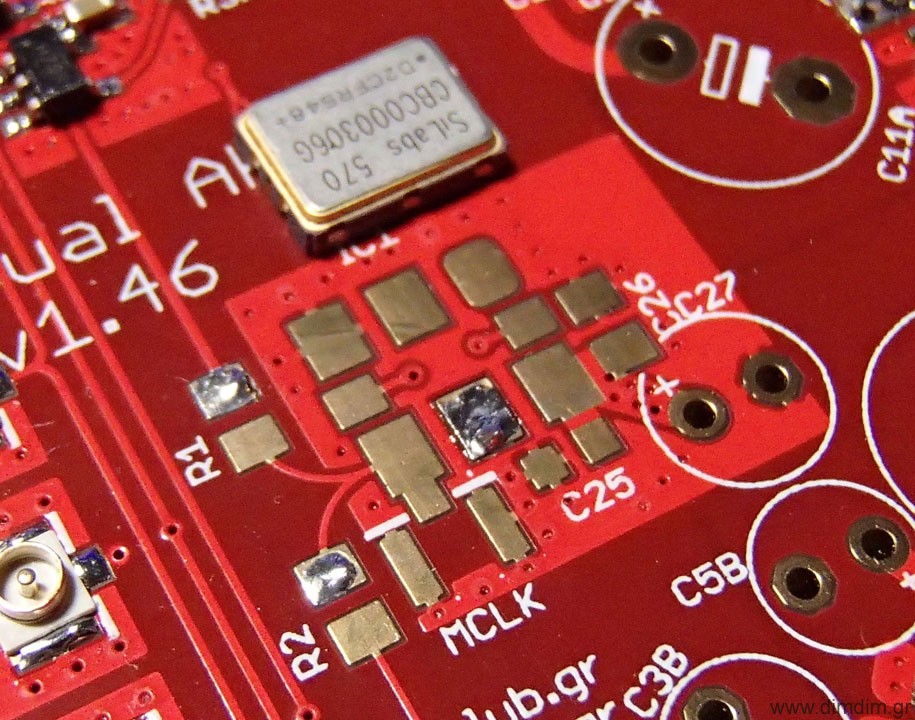
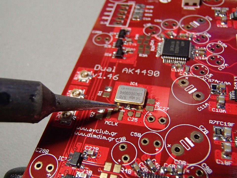
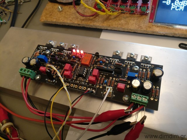
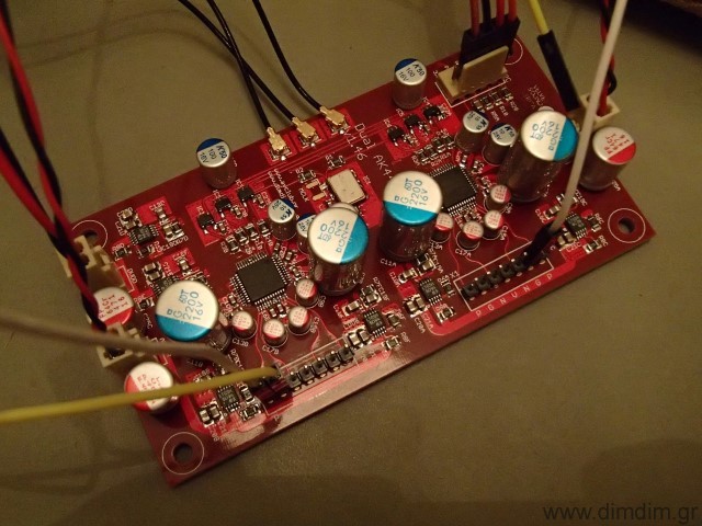
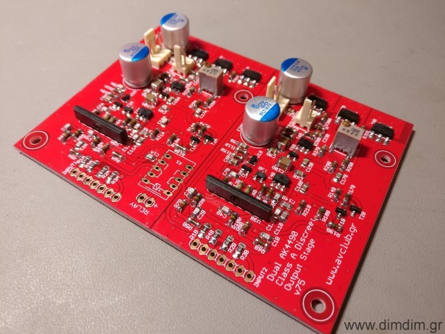
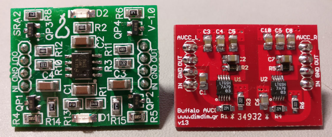
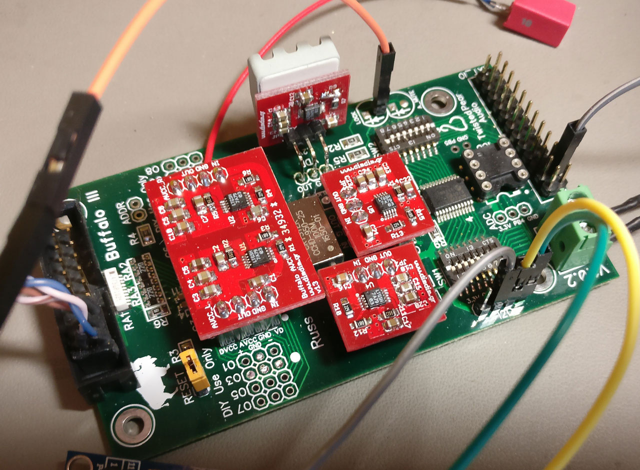
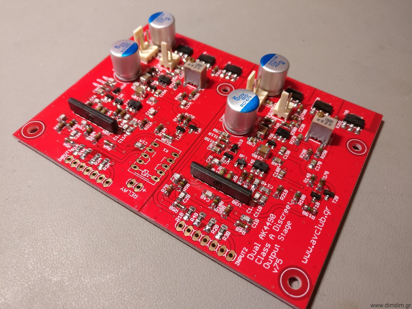
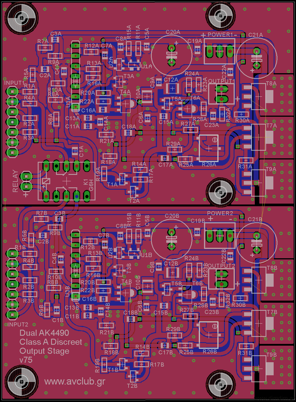
This is the PCB:
And this is the BoM:
The BoM includes part numbers for most parts from Mouser. The only parts that are not in production and must be found elsewhere are the UPA68H. Ebay is a good bet. Chances of getting fake parts are pretty small, but just in case do this to double check the ones that you bought: http://www.diyaudio.com/forums/analog-line-level/296406-salas-dcg3-preamp-line-headphone-post5330311.html (Thank you Salas for the info and the idea to use them in the first place!)
The only parts that need matching are T8A with T9A and T8B with T9B. There’s no need to go crazy with the matching – within 5% should be enough.
Power should be ideally +/-16VDC. A bit less is OK (I did my initial testing with +/-12VDC) but more will most likely damage the board. The board is running in class-A so current draw is constant. A power supply with 100mA current capacity should be enough.
Bias current is adjusted by the multi-turn trimmers R26A and R26B. They should be adjusted to their mid value before soldering to the board (~1K). To adjust bias just measure current consumption at one of the rails while turning the pot. Adjust for ~25mA total current draw per rail and per channel. Current draw on the negative rail should be about 1mA higher than on the positive rail. Bias should be re-adjusted if the power supply voltage needs to change.
After bias adjustment and with no input signal you should check for DC at the outputs. If everything went well you should be seeing anywhere between 0 to a few mV of DC voltage.
A few design notes:
- This design is inverting. I’ve set up my AK4490 code to also invert the 4490’s outputs so as to end up with a non-inverting overall output. But it doesn’t seem to be making much of an audible difference, since I can’t hear a difference as I’m switching between inverting and non-inverting output.
- There is provision for a relay that switches between the default filter for PCM (-3db @ ~90KHz) to a more proper filter for DSD (-3db @ ~50KHz). This feature has not been tested yet..
Regarding the resistors, we’ve chosen to go with mini MELF resistors (type 0204) because of their high quality and in general excellent reputation for audio. We are aware that some of the necessary values ATM are kind of hard to source so we’ve included notes in the BoM with the really critical parts and valid value ranges for the less critical other values. Note that “+/-5% from initial value” does not mean that the parts tolerance can be 5% – it means that instead of for example a 10K resistor you can use a 10K + 5% = 10.5K part. It still has to be matched to its counterpart, of course.
I am including these substitutions, as reference:
Instead of the proposed 604R : —-> https://gr.mouser.com/ProductDetail/Vishay-Beyschlag/MMA02040C6190FB300/?qs=sGAEpiMZZMsU0eETUM64Jwu1lXnAfA1Az%2fUBmHPWxBQ%3d
Instead of the proposed 62R —-> https://gr.mouser.com/ProductDetail/Vishay-Beyschlag/MMA02040C5909FB000/?qs=sGAEpiMZZMsU0eETUM64JzhzDaxYafIopmV6xoU7Pd%2faEeFyYr39dw%3d%3d
Instead of the proposed 49,9R —-> https://gr.mouser.com/ProductDetail/Vishay/CMA02040X3909GB300/?qs=%2fha2pyFaduinSoUQ%252bxM%252bcspKJgxV2WgydeZC1mFkJQ0%3d
Instead of the proposed 499R —-> https://gr.mouser.com/ProductDetail/Vishay-BC-Components/CMA02040X4700GB300/?qs=sGAEpiMZZMsU0eETUM64J9XrXp4g00LTnadULizxluo%3d
Instead of the proposed 33R —-> https://gr.mouser.com/ProductDetail/Vishay-Beyschlag/CMA02040X3309GB300/?qs=sGAEpiMZZMsU0eETUM64J5DAE%2fHuiq02KfqnEeQjWns%3d
Instead of the proposed 10R —-> https://gr.mouser.com/ProductDetail/Vishay-Beyschlag/CMA02040X1009GB300/?qs=sGAEpiMZZMsU0eETUM64J5wRh77yguxgpX8F3yMYvKE%3d
The value of two of the required 1K resistors (the R20A & R20B) is critical, so you should use these —-> https://gr.mouser.com/ProductDetail/Vishay-Beyschlag/CMA02040X1001GB300/?qs=sGAEpiMZZMsU0eETUM64J5DAE%2fHuiq026nqxTapoB%252bc%3d
for the other 6 non-critical 1K resistors you can use these —-> https://gr.mouser.com/ProductDetail/Vishay-Beyschlag/CMA02040X1201GB300/?qs=sGAEpiMZZMsU0eETUM64J5DAE%2fHuiq02Tdrq8lX57XI%3d
The value of the 120R resistors is critical, so are the tolerance of the 49.9R (substitution for 39R) resistors. Their values should be matched.
This concludes Part 3. The next post will detail how everything works together.