Update: TFT HiFiDuino v2.13

I did a little work on the TFT HiFiDuino code, incorporating most of the enhancements I made to the ArDAM1021 code.

v2.13_1

v2.13_4

v2.13_2

v2.13_5

v2.13_3

v2.13_6

These are the enhancements:

  • Option of displaying white text & graphics on black background as well as the “original” look.
  • New encoder code (it requires a new library).

Plus a few minor bugfixes here and there.

The new version of the code is here (v2.13): TFT_HiFiDuino_v2.xx (11152 downloads ) (Note: As always, the code on this page may not be the current one, i.e. there may be a newer version available. The latest version is always up at the project’s official page.)

I will also update the code’s official page with the new version of the code.

Soekris dam1021 ArDAM Project update

Three weeks back I released the first public alpha of the ArDAM code, stating that it was very very alpha. I was meaning every word of that sentence.

Since then, Soren has released the new firmware for the DAM and I have resumed work on the project. Today I am happy to release the first usable version of the code (v0.74):  ArDAM1021 Code (61486 downloads )

ArDAM1021-v0.74-2

Changes include but are not limited to:

  • Tons of bugfixes (volume control, source selection, etc etc).
  • Filter selection either by remote or via rotary encoder (in the settings).
  • Option of displaying white text & graphics on black background as well as the “original” look.
  • New encoder code (it requires a new library).

The download now also includes all the necessary fonts. Let me know what you think.

The project’s page will be edited later today.

Universal Signal Isolator shield for Arduino DUE & MEGA

A few years back I designed a little Arduino shield who’s main function was to provide electrical isolation between an Arduino and a DAC (specifically a TPA Buffalo III).

The years have passed and my needs have changed with the introduction of the dam1021 DAC and its serial interface. My first though was to design a new shield specific to the dam but then I said “why not design a universal isolator shield?”. It would provide electrical isolation for both I2C as well as serial signalling.

Thus was born the Universal Signal Isolator shield for Arduino DUE & MEGA:

v0.97_crop

OK, it does look a lot more complicated than my first shield but remember, you only need to solder in the parts that your DAC actually needs.

So, what does this thing do?

1) Electrical isolation of I2C signals, complete with support of 8 isolated inputs or outputs (via an MCP23008 IC). Three of the MCP’s pins are high current outputs (up to 100mA).

2) Electrical isolation of up to 2 serial ports (implemented with an Si8642).

3) Electrical isolation of the second I2C interface of the DUE (implemented with an ADUM1250).

4) Powered either by 5VDC, 8-15VDC (non-regulated) or 7-12VAC (includes support for on-board rectification and filtering).

5) Support of a 5VDC power relay (up to 100mA).

6) Header for connecting a Nextion display.

7) On-board EEPROM memory (24LC256).

8) And of course full compatibility with the previous shield (same pinouts for the encoders, IR, TFT, etc.).

I will release the Eagle files once I have confirmed that the shield works as expected (I’m waiting for the first (and hopefully last) batch of PCBs).

Soekris dam1021 Arduino Control Code

A few days ago Soren announced that the release of the new firmware for the dam1021 was close.

In light of that announcement I have decided to release the Arduino code that I had written a few months back, even though it is not quite finished.

2015-07-31 18.15.44_res

I am doing this to help fellow Arduino & dam1021 enthusiasts in their quest of remote-controlled color TFT bliss.

So, for now, no real documentation – this is no polished piece of software, but it works (for the most part).

Since it is based on the TFT HiFiDuino code, you can get started by reading its documentation. It should not be hard to get started with this. The code itself also contains useful comments.

I should remind you that the dam1021 at the moment only “talks” real RS-232, meaning that a circuit that converts the TTL level serial port of the Arduino to a real RS-232 port is necessary.
However, we were promised that with the firmware upgrade the second, isolated TTL serial port would be enabled, so here’s hoping..

Also, I have come across a strange problem with the serial communication with the dac. In the beginning all is well but after a while the dam no longer responds to the commands that are sent by the Arduino. However, it (the dam) is still sending data back to the Arduino – when the sampling rate changes, the new SR is displayed properly on the TFT.

I have verified that the Arduino is indeed sending the commands to the dam:

DS1Z_QuickPrint21

DS1Z_QuickPrint22

I hope the problem gets sorted out in the new firmware release.

Anyway, here is the code: ArDAM1021 Code (61486 downloads )  The project also has its own page: https://www.dimdim.gr/arduino/ardam1021-project/

Let me know what you think. I promise to put more work into it in the next few weeks..

Universal USB to I2S Interface Indicator PCB

Over at avclub.gr we designed a custom PCB to ease the implementation of the Universal USB to I2S Interface Indicator. It was a joint effort between myself and Manolis (a.k.a. lemon at avclub.gr). I did the circuit design and Manolis did the PCB design work.

This is the schematic of the final version of the circuit:

USB2I2S schematic 0.8b

When the PCB design was finalized, a GB was organized. When the GB was finished we placed an order on seeedstudio.com’s Fusion PCB service. About 3 weeks later the PCBs had arrived:

IMG_9927

PCB_from_fabThe production quality was truly excellent.

From top to bottom we have:

  • H1: Header for power. It may be either 5VDC (regulated) or 7-12VDC (non-regulated). Pin 1 is 7-12VDC, Pin 2 is GND, Pin 3 is 5VDC.
  • H2: OLED display connector. Pin 1 is 3.3V to the display, Pin 2 is GND, Pin 3 is SCL, Pin 4 is SDA.
  • H3: Header for future expansion. It exposes the unused I/O of the Nano in case it may be of use in the future. The last two pins are buffered by transistors so that they can supply enough current to engage small relays (5VDC, up to 100mA per pin). Pin A7 is connected to JP1_IR as well (see below).

Next up is the socket for the Arduino Nano. You will notice that the USB port should be on the right.

At the bottom of the board we have:

  • JP1_IR: This is a connector for an IR Receiver module. Software support for this is currently in beta. Pin 1 is signal out, Pin 2 is GND, Pin 3 is power (5V). Note that R4 and C5 provide filtering for the power and should be installed. R5 is an optional pull-up resistor. It should not be installed for normal use.
  • H4: This is the “dirty” side of the U1 isolator. Pin 1 is Vdd (usually 3.3V or whatever your USB Interface module uses for its logic levels). Pins 2 through 7 are inputs and Pin 8 is GND.
  • H5: This is the “dirty” side of the U2 isolator. Pin 1 is Vdd (usually 3.3V or whatever your USB Interface module uses for its logic levels). Pins 2 through 5 are inputs and Pin 8 is GND.

Note that in the future a Si8642BA may be used in place of U2. With proper support from the code that will turn 2 of the 4 inputs into outputs, so that they may be used to control a DAC board (for example to select an input).

This is the full BoM:

Part Description
FB1, FB2, FB3 Ferrite Bead 0805
R1 2.7K 0805
R2, R3 8.75K 0805
R4 100R 0805
R5 10K 0805 (optional)
C1, C2, C3, C4 100n X7R 0805
C5 10uF 10V X7R 0805
Q1, Q2 BC808 or equivalent SOT-23
U1 Si8065AA-B-IU
U2 Si8045AA-B-IU (optionally Si8642BA-B-IU)

In case you want to have your own PCBs made, these are the Gerber files: Universal USB to I2S Interface Indicator PCB Gerbers (4979 downloads )

You will also need an Arduino Nano, a suitable OLED display and some cables, connectors, etc. (see project page).

As soon as I received the boards, I built a prototype with whatever components I had lying around (thus the wrong size of most of the resistors & capacitors).

Prototype PCB

And proceeded to test it out with an Amanero Combo384 board:

Everything worked as it was expected. 🙂

At the moment this board (and relevant Arduino code) has been tested with the following USB to I2S interfaces:

Amanero Combo384
hookup_amanero_v2Note that R1 should be installed for proper operation.

DIYINHK XMOS
hookup_diyinhk_xmos_v2

JLSounds I2SoverUSB
hookup_jlsounds_v2

Luckit WaveIO
hookup_waveIO_v2
You will notice that there is no Vcc pin on J9. In order to power the isolator, we will have to “steal” power from elsewhere on the board. A good place to tap is the power pin of the on-board I2S isolator, just to the left of the I2S LRCK U.FL:
hookup_waveIO_power

Universal USB to I2S Interface Indicator feature upgrade

Following up on a number of feature requests made over at avclub.gr I made a few rather interesting additions to the code:

1) The OLED display will show the type of signal (PCM or DSD) for 3 seconds if a change in signal type occurs. Only supported on USB interfaces that support it (obviously).

2) IR remote control support via the well-known IRremote Library. Support for power on/off and source selection (S/PDIF or USB).

3) The OLED display will display the name of the selected source, permanently if it is S/PDIF or for 3 seconds if it is USB.

More details on the new features will be added to the project’s home page, as will the new version of the code.

Here is a short video of the prototype in action:

Arduino: ENC28J60 LAN module

I bought this inexpensive (something like $3 delivered) Ethernet module a few years ago, only to discover that there really wasn’t a decent library to support it. So it got tossed into a drawer..ENC28J60%20Ethernet%20Module1[1]A few days ago I realized that I needed a low cost Ethernet interface for one of my projects. It wouldn’t really need to do much, so I thought the ENC28J60 would probably be able to handle the task.

Doing the customary Google search for Arduino support turned out a full Ethernet library for it! 🙂

It’s called UIPEthernet and it is fully compatible with the original Ethernet library for the Arduino. What this means is that every piece of code written for the Ethernet library (in other words for the “classic” Arduino Ethernet Shield) can be made to work with a dirt-cheap ENC28J60 just by changing
#include <Ethernet.h>
to
#include <UIPEthernet.h>

This I had to see for myself, so I hooked it up.

The module that I have needs 3.3V power (not 5V!!) but its SPI pins are 5V tolerant so it will pair nicely with any Arduino.
The necessary hookup for the UNO, MEGA or DUE can be found in the library’s page: https://github.com/jcw/ethercard

I decided to try a classic Ethernet example sketch: The WebServer sketch. This one reads a few analog inputs on the Arduino and then serves them on a web page.

Sure enough, all I had to do to get it to work was just change the #include statement. It worked like a charm!

WebServer running

So, there you have it. You can add full wired Ethernet connectivity to your Arduino for less than $3.

Soekris R-2R: Interfacing to an Arduino

The Soekris dam1021 has a serial port (J10).J10-serial
This serial port serves a number of purposes:

1) It is used for uploading firmware updates via the uManager prompt.
2) It is used for uploading filter values via a software utility (not yet released).
3) Outputting info on currently selected Input, Sampling Rate and Volume level.
4) Controlling things by receiving commands. Up to now, we can select Input and change the Volume. More commands might be added in the future (or already exist, but are not yet documented by Soren).

In order to do all those things, one has to interface to this serial port. In this post I detailed how to interface a computer to this port (so as to perform a firmware upgrade). Now it is time to do the same for a microcontroller, say an Arduino.

The problem is, microcontrollers use different voltage levels compared to the “classic” RS-232 serial protocol. In order to make these different things talk to each other, we need to use what is called an “RS-232 Receiver / Transmitter” IC. Such ICs are pretty commonplace, since they are found inside of most devices that come with RS-232 interfaces. The “classic” IC that is used is the Maxim MAX232. It is very low-cost but it is also an old design, requiring 5V (instead of 3.3) and 5 x 1μF capacitors. There is a much newer version of the chip, the MAX3232, operating with a voltage between 3V and 5V and requiring much smaller caps (0.1μF), but it is not as widely available as the MAX232. Since I was in a hurry to get things up and running, I chose what I could find locally in stock: a MAX232.

MAX232

This meant that I had to power it with 5V and use 1μF tantalum or ceramic capacitors, but what the heck. I was in a hurry.

After reading the MAX323’s data sheet I ended up with this:

RS-232-interface_v2_bb
(click on the picture for a higher resolution version)

You will notice that I am using Serial3 of the DUE to talk to the DAM DAC. Any serial port could be used, but I chose Serial3 because it was practical – it will be easy to route these specific pins on the shield that I am designing.

Once I verified that the above circuit worked, I built it on perfboard to keep handy:

MAX232_interface

The above circuit works in general but has some trouble with the DAM DAC. It works just fine upon power up but at some point loses communication with the DAC. The only way to restore communication is to power cycle the DAC. I am not sure what the problem is, but I suspect that it has to do with the power management features of the ICL3221 chip used on the DAM. I have ordered an ICL3221 to use in place of the MAX232, in hope that everything will work fine when I use this (at least in theory) fully compatible IC.

Stay tuned.

Arduino and SPI TFT LCDs

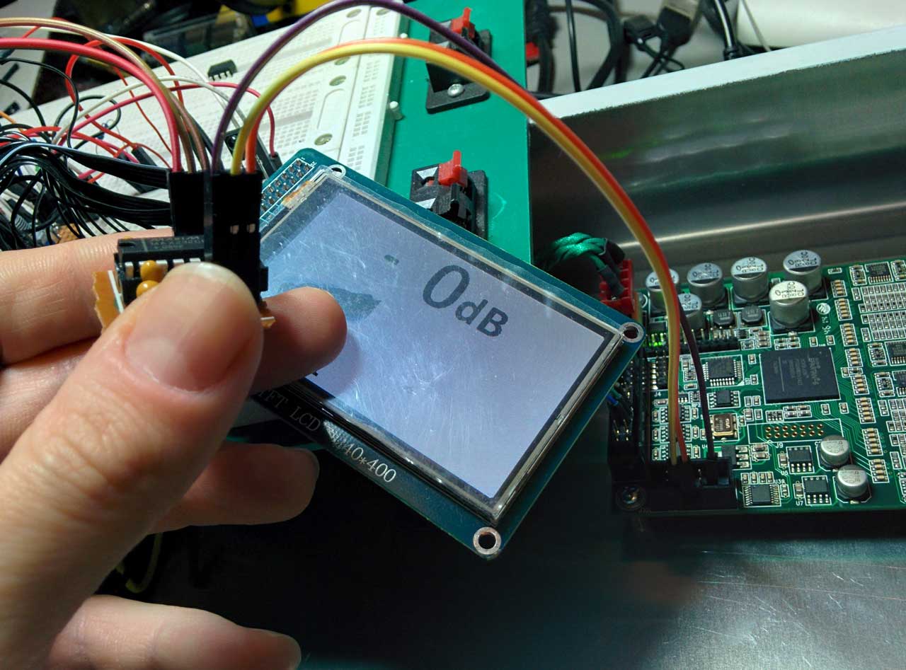
I love TFTs because one can make with them professional looking project displays without necessarily breaking the bank.

I am particularly fond of the SPI interface because it uses a minimum number of I/O pins. This means that since even a minimal Arduino (one based on an ATmega328) can drive a low-cost TFT with I/O left for other tasks, the cost may be kept down. Nowadays, it is realistic to implement a basic Arduino with a 2.2″ TFT for less than 10€. An ATmega328 with an Arduino bootloader goes for 1,50€ on Ebay, a 2.2″ SPI TFT goes for about 3,50€, so “vintage” character LCDs are definitely on their way out.

So, let’s get down to business. What does one need in order to get one of these displays to work?
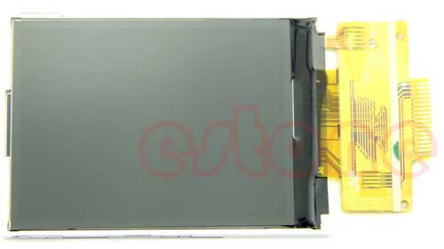
Obviously, you need the TFT display itself. I don’t care where you buy it from – you may get it from Adafruit or SparkFun or iTead or any one of the “big name” shops or you may get it from Ebay (a.k.a. “China”). In my experience, it doesn’t really matter as long as you know what you are purchasing. For example, on Ebay when you search for 2.4″ SPI TFT LCD you will come across this:

$_57_crop_res

and this:

$_57-(1)_crop_res

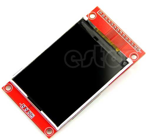
They are essentially the same TFTs, but the first one is ~1€ cheaper than the second one. The difference is the PCB that is included. Do not underestimate this PCB. If you go for the plain TFT you will have to solder it to a suitable PCB like this one:

2014-11-25 00.42.57_resize

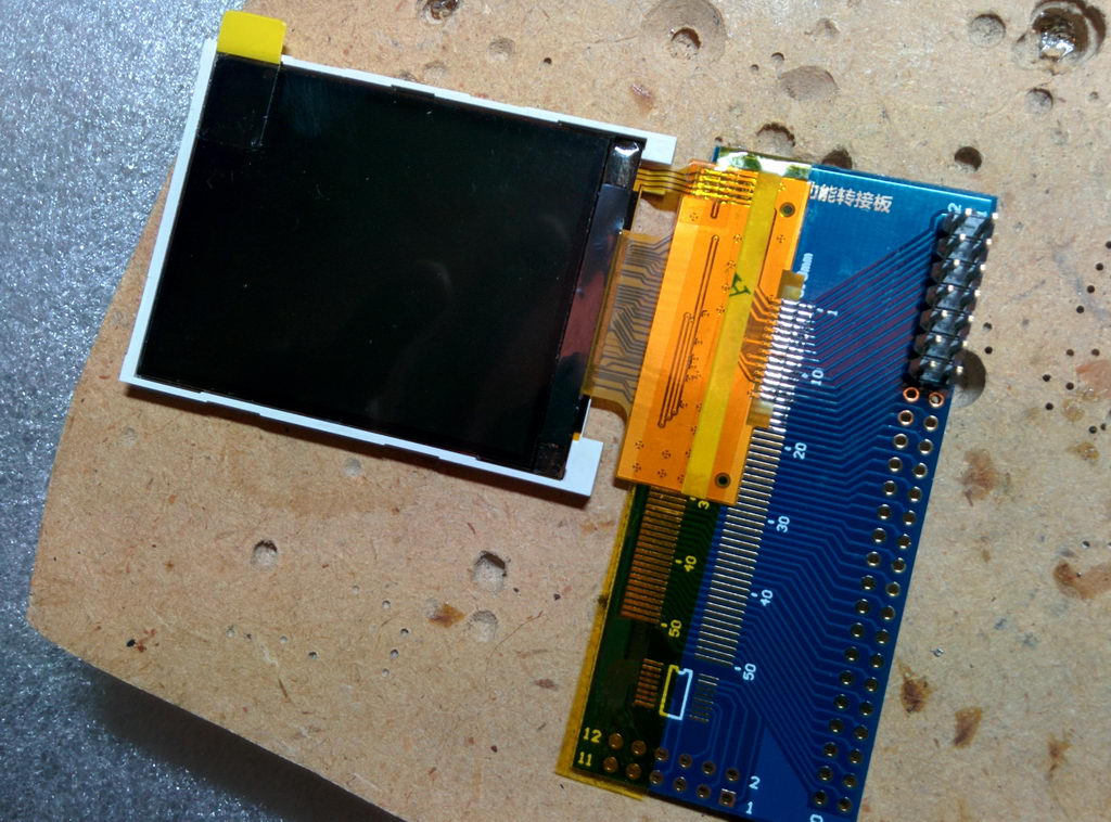
Sure, it is no herculean task, but the TFT + adapter will most likely cost more than a TFT pre-mounted on a PCB.

Rolling your own PCB is indeed an option, but IMHO it is not worth it, not unless you are planning to go into mass production. For 1 or 2 pieces just do yourself a favor and shell out the extra €. You won’t regret it.

But let’s backtrack just a bit. How does one select a TFT? Surely, one would think that size and resolution are the most important factors. I say sure, as long as you have the software part covered. In order to actually show stuff on a TFT you need an appropriate library. You should not take for granted that such a library indeed exists for that gorgeous hi-res IPS TFT that you found for 10€ on Ebay. Many sellers on Ebay just write the word “arduino” on the TFT’s description without giving it much serious thought. Plus you should expect zero (0) support from most Ebay sellers. Most of them can’t and won’t help you if you run into trouble with your code.

So, you should always do a little research. Google is your friend. A good start is Karlsen Henning’s UTFT library. Being billed as a Universal TFT Library it does indeed support a large number of TFT controllers. If your display’s controller is included in UTFT’s compatibility list, you are somewhat covered. I say somewhat because UTFT is not always the best choice since it has a pretty heavy footprint. It will consume the better part of an ATmega328’s flash memory capacity. Fortunately, there are other libraries out there. I will go into more detail later on.

So, you got a TFT and are faced with the task of hooking it up to the Arduino. Relax, it’s simple. You only need to connect 4 or 5 wires, plus power and GND. Let’s start with the basics.

1) Power (Vcc). Most displays need 3.3V to function. This is a requirement of the TFT panel itself as well as of the driver IC that is always part of the assembly (it is an embedded part – you can not really see it). But as you probably know, most Arduinos run on 5V. Display manufacturers that make products for Arduino of course know that and usually include an on-board regulator that takes 5V as input and gives the necessary 3.3V. In most cases there is a selector on the PCB (jumper, solder bridge, or something) that lets you configure the board for 5 or 3.3 volt operation. Look out for that.

2) LED power. This pin controls the backlight of the TFT panel. It consists of a number of LEDs, depending on the size of the LCD panel. Bigger panel means more LEDs and thus more power consumption. It is usually connected to GND or to 5V/3.3V. Some times a current limiting resistor is also necessary. Other times the resistor is built-in and so is a mosfet that allows you to adjust the LED backlight’s brightness by connecting it to a pin that supports PWM (some of the more expensive TFTs support this). In any case, read the manual. You may come across a Chinese TFT that you had to have but then noticed that it has sparse if any documentation. If this happens, play it safe by connecting the LED pin to GND through a resistor (a few hundred ohms is usually a good starting point). If it lights, it means that the polarity is OK. If it does not, try applying 5 or 3.3V to it (through the resistor). If it lights but is too dim, use a smaller resistor. Usually each LED draws about 10-15mA, so if you know how many LEDs your TFT uses you can estimate its power draw and thus select a proper resistor.

3) Signalling. This is the nice part about using SPI: you only need 4 or 5 wires.
CLK (or SCLK / SCK): This is the clock input pin.
MOSI (or SDI / SDA): This is the Master Out Slave In pin. The actual raw data that is sent to the TFT passes through this wire.
CS (or TFT_CS or LCD-CS): This is the chip select pin.
D/C (or A0 or RS): This is the Data or Command selector pin.

We also have the Reset pin. Some times you can get away with connecting it to the Arduino’s reset pin, but it is better to connect it to a normal pin in order to have better control over it.

A special note here: Signalling is usually done at 3.3V unless the TFT’s manufacturer has implemented some kind of level shifting on board the PCB. This level shifting may be done by an IC (best case), or a bunch of transistors and resistors (fair enough..) or just 1.2K resistors (a bit of a kludge, but it usually works). It is important to be careful not to send 5V into a TFT that only supports 3.3V logic because in that case you will most likely damage the TFT.

At this point you need to take a break from the hardware and consider the software, since your choice of library will dictate the particulars of the next step, which is the connection of the signal wires to the Arduino.

Your main choices are two: the UTFT library and the Adafruit GFX library.

Each library has its strengths and weaknesses.

UTFT
Pros:

  • Very nice text support, especially with the add-on UTFT_DLB. Any TrueType font can be converted into a UTFT font of any size with minimum effort.
  • It is indeed universal. You only need to change one parameter in your code to support a different TFT. One library to rule them all, etc.

Cons:

  • Memory consumption. Nice fonts come at a price. No big deal if you have a MEGA or DUE, but makes things pretty cramped in an ATmega328.

Adafruit GFX
Pros:

  • Relatively small footprint.

Cons:

  • Ugly (blocky) fonts if you scale them to a non-native size. This is being fixed by 3rd party code that now supports a small number of proportional fonts but is nowhere near as versatile as UTFT’s code.

You really should become familiar with both of them since different projects will steer you towards one or the other.

Depending on your choice of library, you may need to use the hardware SPI pins for CLK and MOSI or you may be free to use any pins you like. It really just depends on the library.

Each of the libraries uses a slightly different notation for the signal pins. I will try to sum things up in this table:

[table “” not found /]

You may notice that most libraries say that you can just connect the TFT Reset pin to the Arduino Reset Pin. If you do that, you should put 0 as the reset pin.

Good luck!