ArDAM Lite custom PCBs for diyaudio.com

This post serves mainly as a placeholder for the build guide that I wrote for the PCBs, since it seems that some people had problems with the download link that I provided.

The build guide can be downloaded by clicking here: ArDAM Lite Build Guide (41210 downloads )

I do have a few left over PCBs, if you’re interested contact me for more info.

Universal Signal Isolator Shield: Rev. 1.2

Since there has been a lot of interest in my Isolator shield these past few months, I have been optimizing its design.

The result of this optimization is this PCB:
Rev.-1.2-pic
It’s called “the Rev. 1.2”.

Nothing major has changed. The pinouts are still the same, the major components are the same, the functionality is essentially the same.

The changes are as follows:

  • New SPI header. It just passes through the SPI signals, nothing more. It does not connect to anything on the board.
  • New SPI_CS header. Useful only if / when connecting SPI peripherals.
  • Reset button. Because you never know..
  • New circuitry for the POWER_RELAY header. It now uses a MOSFET and it includes a diode for the reverse current coming back from the relay’s coil.
  • Decoupling cap for the IR receiver. Not absolutely necessary, but good to have.
  • More decoupling for the DC_UNR input.
  • Ground planes. Lower Arduino noise, at least in theory.

Here is the updated parts placement:
USI-parts-placement-rev1.2

And this is the updated BoM:

[table “” not found /]

Soon I will update the shield’s page with the new info.

They’re here!

I’m talking about my new Universal Signal Isolator PCBs:

USI_bare_slanted USIs_bunch

IMG_0320_res

I built one to test it out and everything seems to be working as it should. Next step is a page for the project, with schematics, a BoM and build instructions.

It is compatible with the current versions of both the ArDAM1021 and TFT HiFiDuino projects.

For now you can find more info in this post.


Universal Signal Isolator shield for Arduino DUE & MEGA

A few years back I designed a little Arduino shield who’s main function was to provide electrical isolation between an Arduino and a DAC (specifically a TPA Buffalo III).

The years have passed and my needs have changed with the introduction of the dam1021 DAC and its serial interface. My first though was to design a new shield specific to the dam but then I said “why not design a universal isolator shield?”. It would provide electrical isolation for both I2C as well as serial signalling.

Thus was born the Universal Signal Isolator shield for Arduino DUE & MEGA:

v0.97_crop

OK, it does look a lot more complicated than my first shield but remember, you only need to solder in the parts that your DAC actually needs.

So, what does this thing do?

1) Electrical isolation of I2C signals, complete with support of 8 isolated inputs or outputs (via an MCP23008 IC). Three of the MCP’s pins are high current outputs (up to 100mA).

2) Electrical isolation of up to 2 serial ports (implemented with an Si8642).

3) Electrical isolation of the second I2C interface of the DUE (implemented with an ADUM1250).

4) Powered either by 5VDC, 8-15VDC (non-regulated) or 7-12VAC (includes support for on-board rectification and filtering).

5) Support of a 5VDC power relay (up to 100mA).

6) Header for connecting a Nextion display.

7) On-board EEPROM memory (24LC256).

8) And of course full compatibility with the previous shield (same pinouts for the encoders, IR, TFT, etc.).

I will release the Eagle files once I have confirmed that the shield works as expected (I’m waiting for the first (and hopefully last) batch of PCBs).

Soekris R-2R: Interfacing to an Arduino

The Soekris dam1021 has a serial port (J10).J10-serial
This serial port serves a number of purposes:

1) It is used for uploading firmware updates via the uManager prompt.
2) It is used for uploading filter values via a software utility (not yet released).
3) Outputting info on currently selected Input, Sampling Rate and Volume level.
4) Controlling things by receiving commands. Up to now, we can select Input and change the Volume. More commands might be added in the future (or already exist, but are not yet documented by Soren).

In order to do all those things, one has to interface to this serial port. In this post I detailed how to interface a computer to this port (so as to perform a firmware upgrade). Now it is time to do the same for a microcontroller, say an Arduino.

The problem is, microcontrollers use different voltage levels compared to the “classic” RS-232 serial protocol. In order to make these different things talk to each other, we need to use what is called an “RS-232 Receiver / Transmitter” IC. Such ICs are pretty commonplace, since they are found inside of most devices that come with RS-232 interfaces. The “classic” IC that is used is the Maxim MAX232. It is very low-cost but it is also an old design, requiring 5V (instead of 3.3) and 5 x 1μF capacitors. There is a much newer version of the chip, the MAX3232, operating with a voltage between 3V and 5V and requiring much smaller caps (0.1μF), but it is not as widely available as the MAX232. Since I was in a hurry to get things up and running, I chose what I could find locally in stock: a MAX232.

MAX232

This meant that I had to power it with 5V and use 1μF tantalum or ceramic capacitors, but what the heck. I was in a hurry.

After reading the MAX323’s data sheet I ended up with this:

RS-232-interface_v2_bb
(click on the picture for a higher resolution version)

You will notice that I am using Serial3 of the DUE to talk to the DAM DAC. Any serial port could be used, but I chose Serial3 because it was practical – it will be easy to route these specific pins on the shield that I am designing.

Once I verified that the above circuit worked, I built it on perfboard to keep handy:

MAX232_interface

The above circuit works in general but has some trouble with the DAM DAC. It works just fine upon power up but at some point loses communication with the DAC. The only way to restore communication is to power cycle the DAC. I am not sure what the problem is, but I suspect that it has to do with the power management features of the ICL3221 chip used on the DAM. I have ordered an ICL3221 to use in place of the MAX232, in hope that everything will work fine when I use this (at least in theory) fully compatible IC.

Stay tuned.

Soekris R-2R: Firmware upgrade

The DAM1021 originally came with FPGA firmware 0.8. Since then Soren has released a new version of the firmware, Rev 0.9.

J10-serial
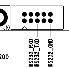
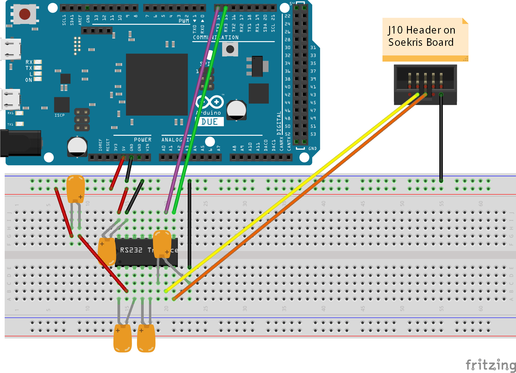
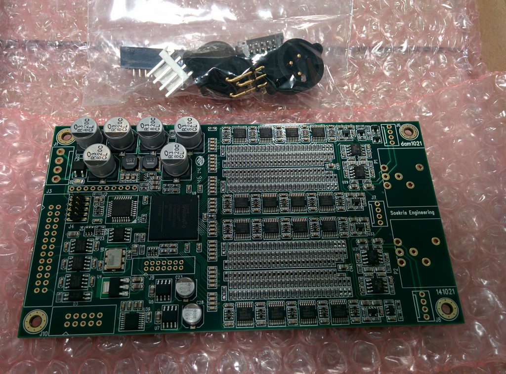
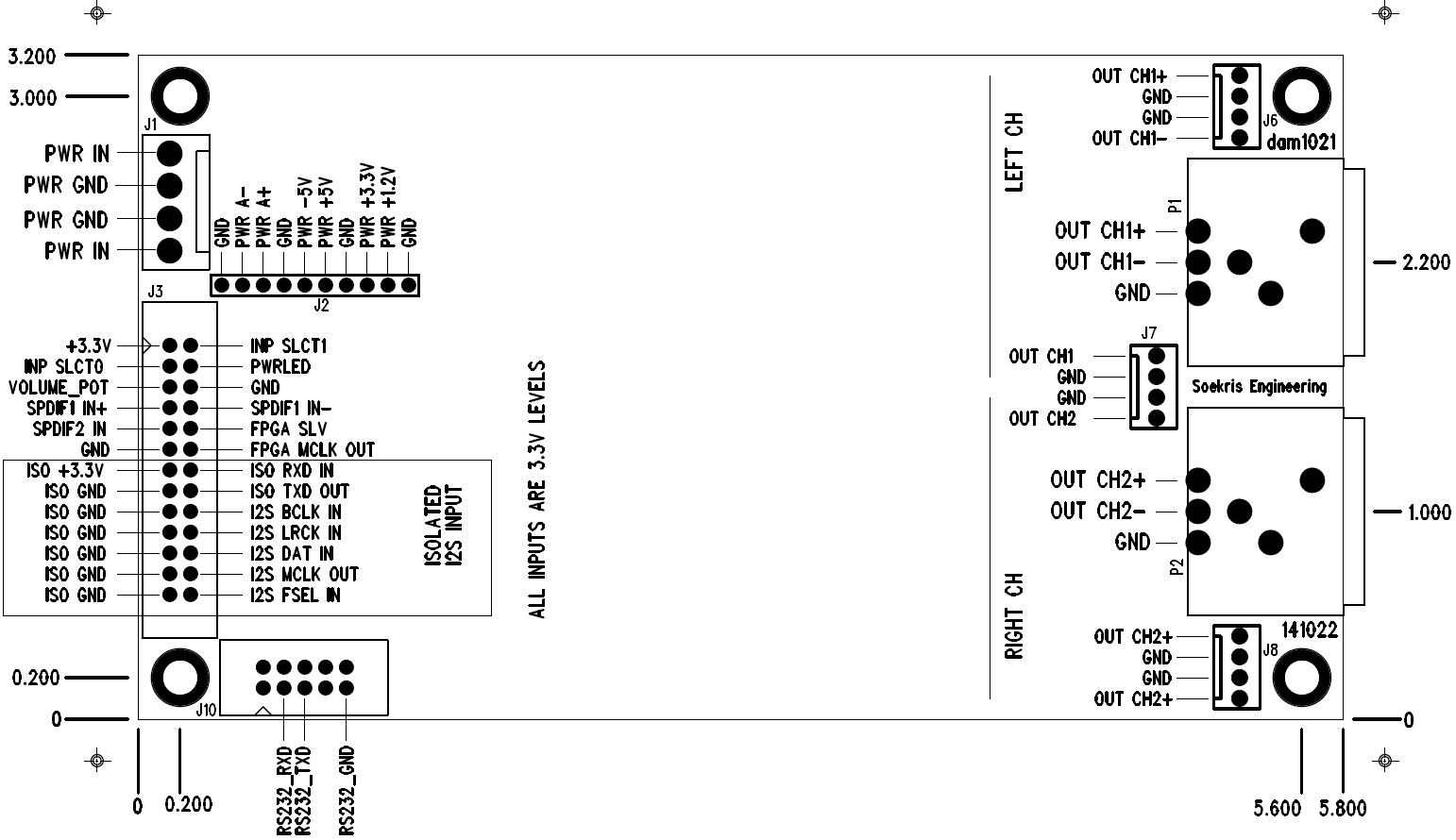
In order to upload it to the DAC one must connect the DAC to a computer using either a “classic” serial port, like the one found at the back of older computers, or a USB to Serial adapter. Then a cable must be made connecting three pins of the DB9 connector to the connector J10 on the DAC board.

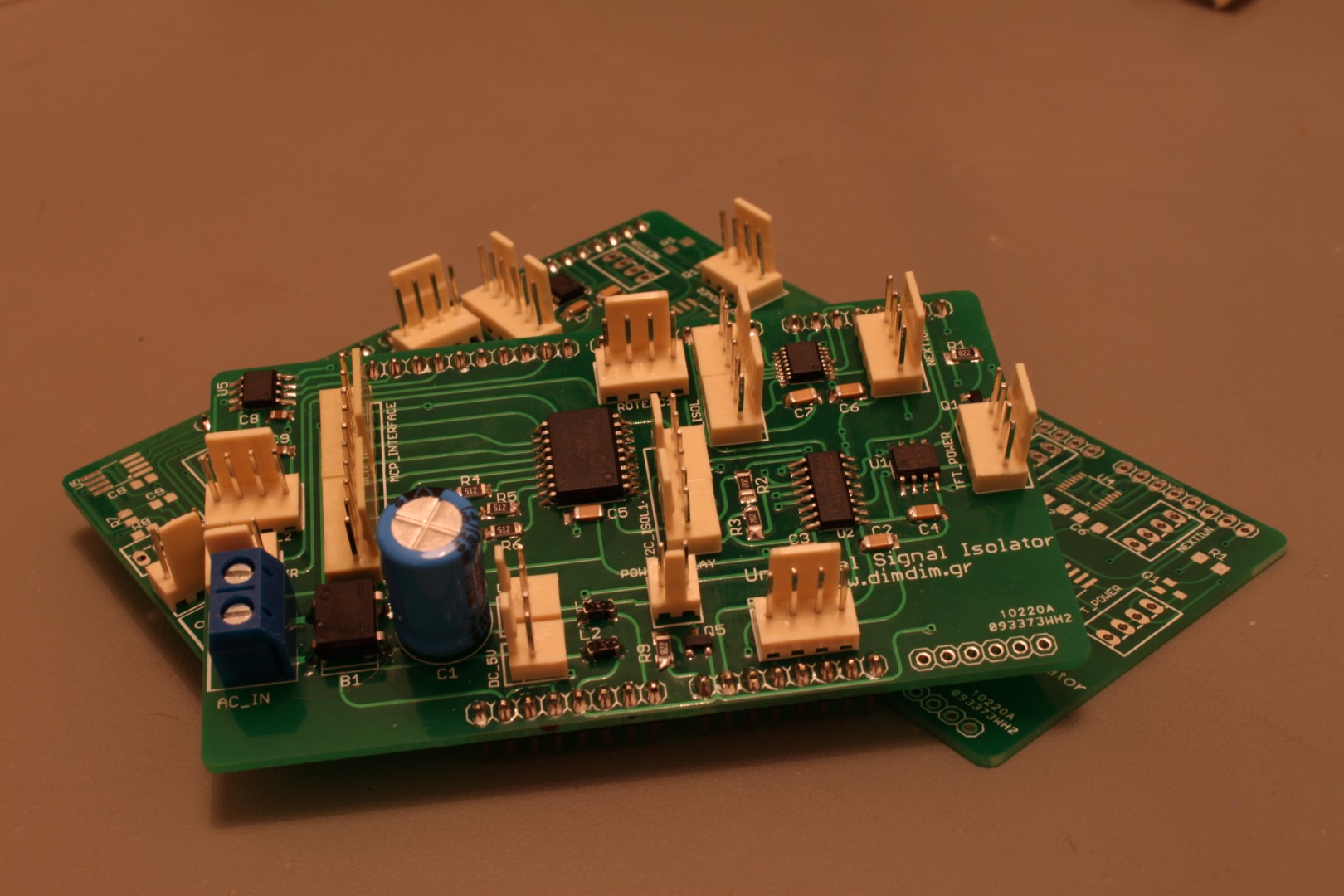
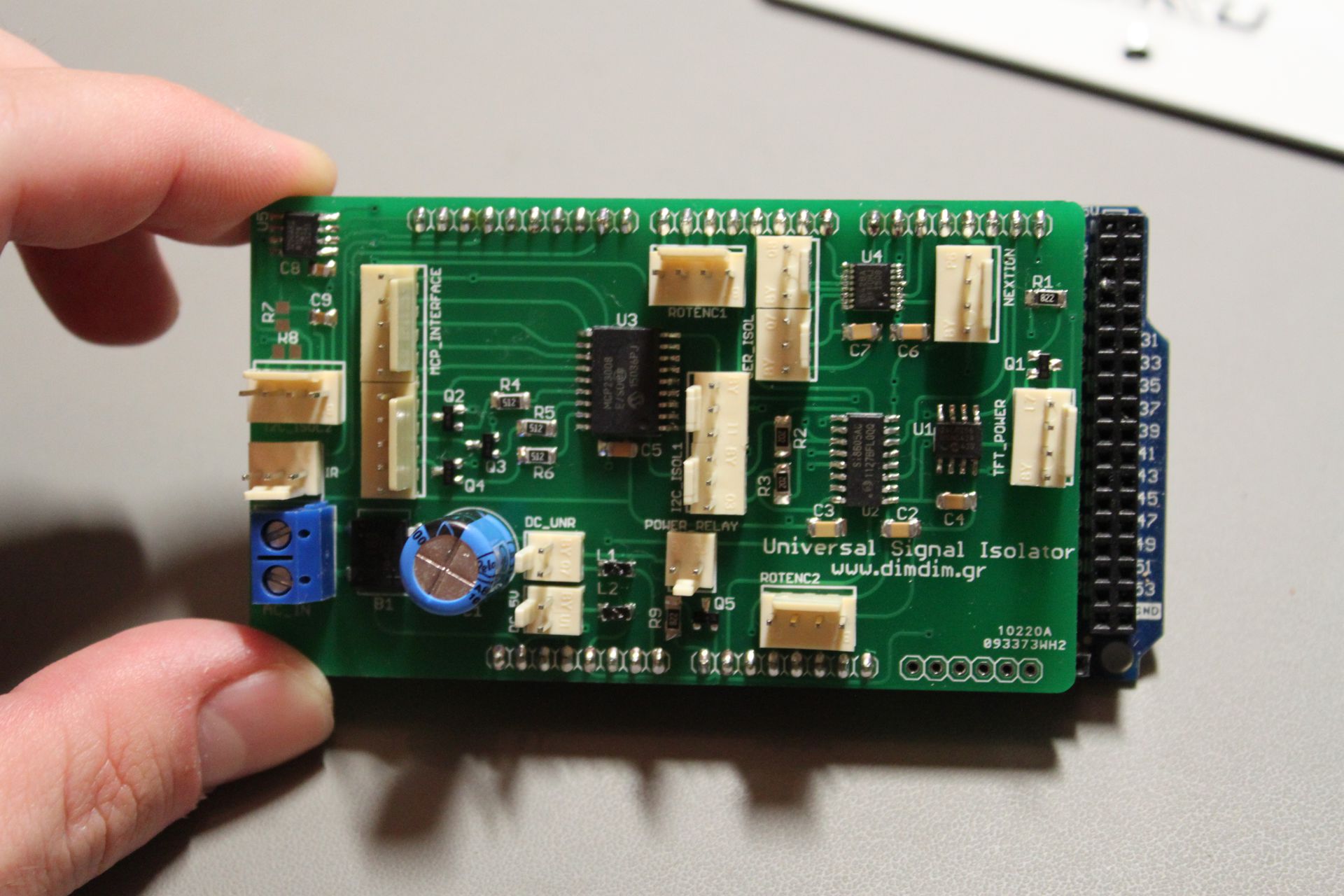
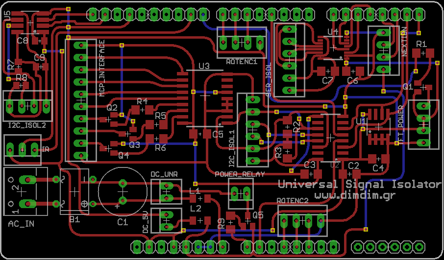
These pictures illustrate the connections that are needed:

RS-232_to_Soekris

RS-232_to_Soekris_2

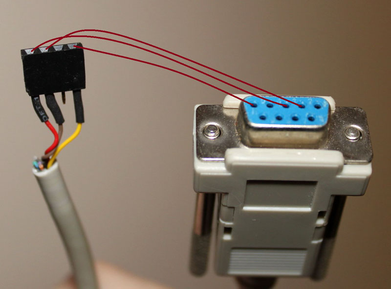
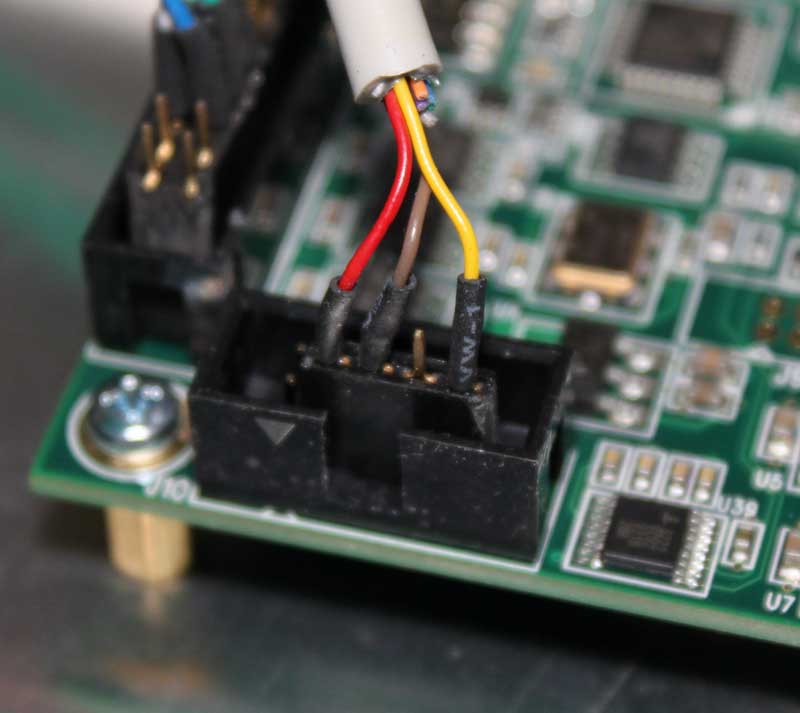
You use your new cable to connect the DAM to your computer’s serial port (or USB-to-serial adapter). You do not power on the DAM DAC just yet.

Once you are done with making the physical connection, you need to get your hands on some software that supports the XModem 1K data transfer protocol. This is a pretty old protocol, so your choices in software are pretty limited. One such choice is the “classic” HyperTerminal, but since it is no longer available with Windows I chose the more modern ExtraPUTTY. It is a fork of the classic PuTTY telnet/ssl client software that also supports “vintage” transfer protocols such as XModem.

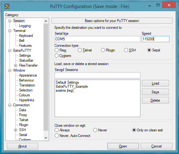
Once you have it installed it is pretty easy to establish a serial connection at 115200, 8, n, 1, as specified by Soekris. You click on the “serial” tickbox and enter your computer’s serial port (in my case it’s COM5) along with the specified speed (115200bps):

ExtraPutty-configuration

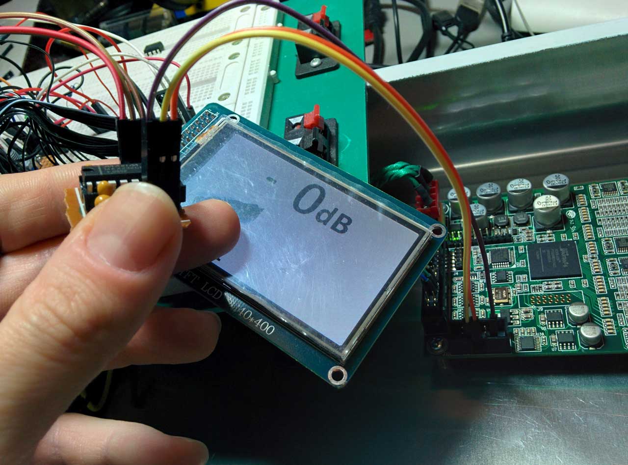
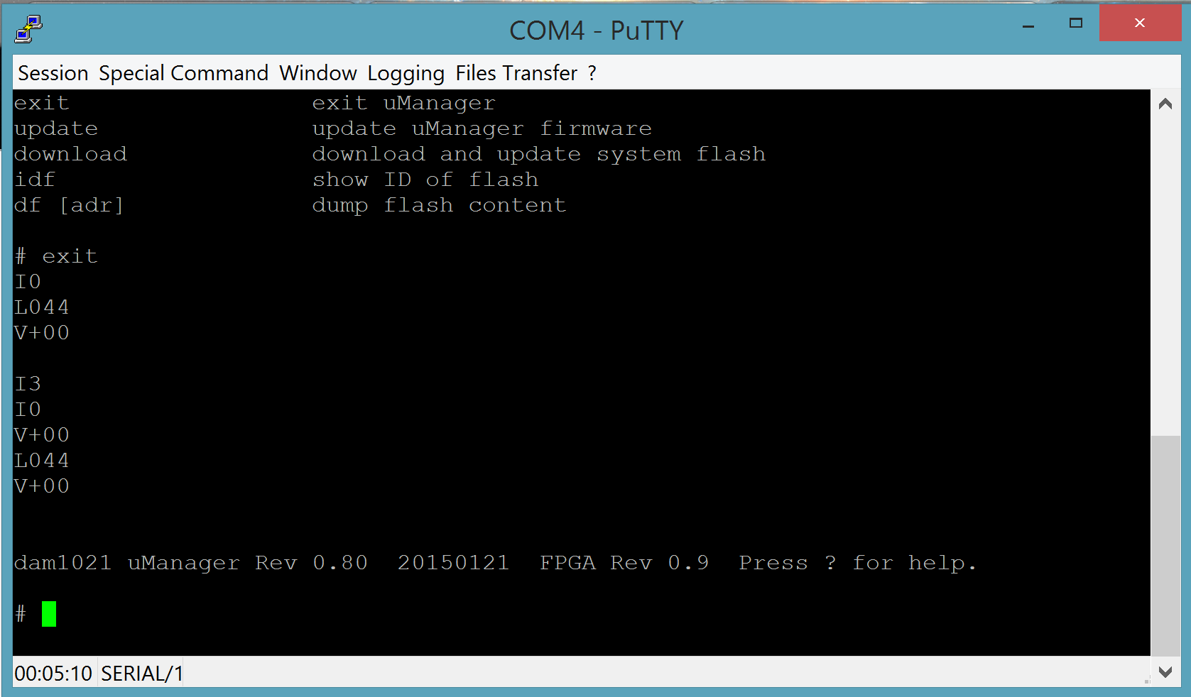
You click on “open” and you get a black terminal screen. You now need to power on the DAC. Once you do that, you should get something like this:

ExtraPutty-after-power

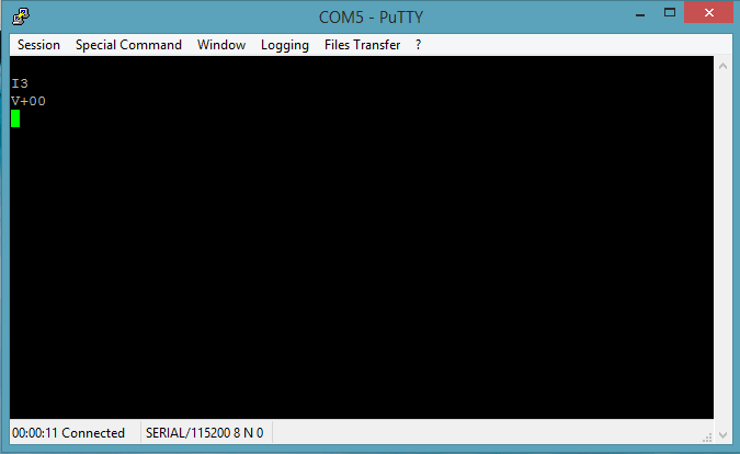
This means that everything is fine. You might see an “I0” instead of an “I3”. That is OK.

Now you need to get to the uManager prompt. You type “+++” and wait for a second. You will not see the “+” characters as you type them. That is OK. You will get this:

ExtraPutty-uManager

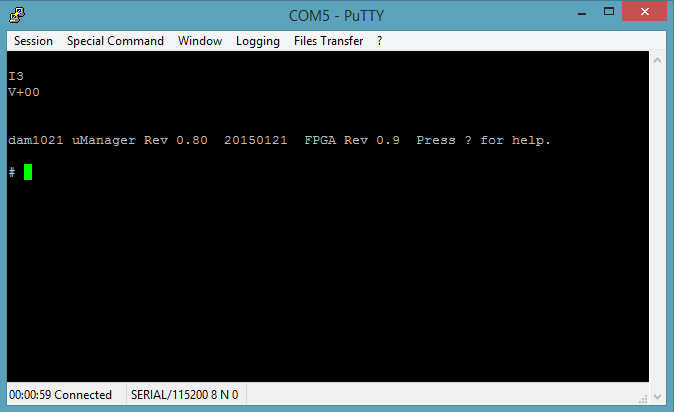
Now type “download”, followed by Enter. You will see something like this:

ExtraPutty-uManager-send

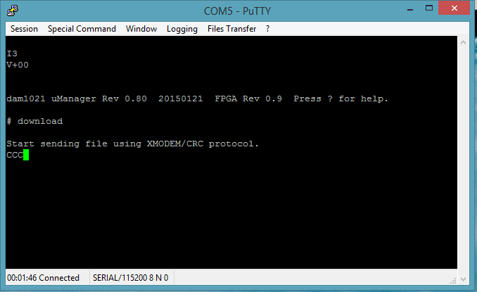
This means that you have 30 seconds to begin sending your file. To do that you click on File Transfer -> Xmodem 1K -> Send. Select your firmware file and off you go!

firmware upload (crop)

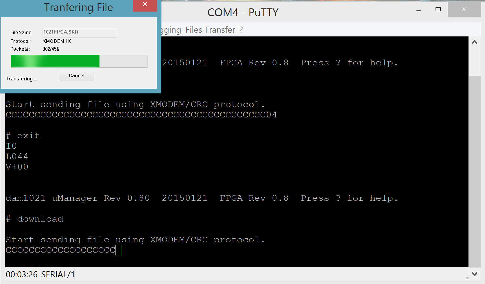
When the transfer completes you will see something like this:

ExtraPutty-uManager-done

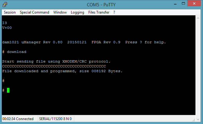
One thing – do not forget to give the “update” command once you have uploaded the code followed by a “y” and return.

Next you type “exit” (and Enter) to exit the uManager prompt and you are ready to power cycle the DAC. Once you have done that, you repeat the above steps to get to the uManager prompt and you verify that you have successfully updated the firmware. You should now be at FPGA firmware 0.9!

firmware upload 0.9 installed (crop)

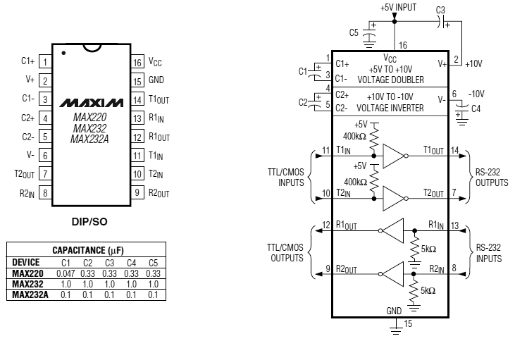
If are having problems connecting, such as getting garbage like this in your serial console:

screenshot terminal jibberish 2

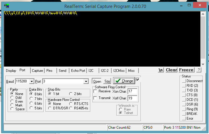
chances are that your USB to serial adapter is not a “true” RS-232 interface, but outputs TTL levels instead. You can confirm that by measuring the voltages between GND and the RX & TX pins. You should be getting zero volts in one case and about -9V in the other. If you are getting 3.3 or 5 volts, your interface will not work with the DAM. You should try to find a proper RS-232 interface.

The Soekris R-2R DAC

The UPS guy just dropped off my brand new Soekris R-2R DAC:

2015-01-30 13.55.04_resize

Also known by the very bland designation “DAM1021”.

It is a sign-magnitude R-2R DAC (a.k.a. “ladder” DAC), meaning that it is quite different in operation than the regular run-of-the-mill DACs.
It is more like a PCM1704-based DAC but with 192KHz+ support plus a bunch of high tech goodies, such as a built-in FIFO buffer.

It is available in three versions, with resistors of different tolerances (0,01% (high grade), 0,02% (mid), 0,05% (basic)). I got my hands on the 0,02% version.

It has three inputs:
1) I2S (electrically isolated)
2) Coax s/pdif
3) TTL for a Toslink receiver

Board-diagram

It is powered directly by a 2 x 7-8V transformer, but may be powered by a bipolar DC power supply.

It outputs a single ended signal at 1.4V RMS and also has a buffer for balanced output at 4V RMS.

It has a serial port for firmware upgrades as well as control.

I have already began work on a Soekris R-2R version of my TFT HiFiDuino Arduino code, tailored to controlling this particular DAC via its serial port.

The board will of course get its own page pretty soon.. Edit: the board now has a page.

To do: hook the board up and actually listen to it play. Stay tuned.