Laying out a display is hard work..

..especially if you have almost no technical constraints in what you can implement. It’s only pixels, after all.

Yes, I am talking about a new version of the TFT HiFiDuino code with a new look and feel.

2014-12-14 21.50.50_resize

This of course is very very preliminary, and chances are the final version will look almost nothing like it, but still it will give you an idea as to where I’m going with the design.

The new version will have a minimal main display and only show the good stuff when an adjustment is to be made. The underlying code is nearly complete, but I’m struggling with the aesthetics of the thing.

But in any case, it won’t be long now. 🙂

TFT HiFiDuino v1.06

Here is version 1.06 of the code: TFT_HiFiDuino_v1.06b.zip (4722 downloads )
(11/12/2013: Update to v1.06b. Reason: minor bugfix)  (Note: As always, the code on this page may not be the current one, i.e. there may be a newer version available. The latest version is always up at the project’s official page.)

IMG_6903_fix_&_crop_res

IMG_6905_crop_res

The main difference is the support of Buffalo 3SE as well as an “always on” feature that bypasses the remote on/off sections of the code.

Here is the official change log:

– Compatible with Buffalo 3 and Buffalo 3 SE. Just comment out the relevant statement.
– Fixed “OS Filt” & “SR disp”.. They were not working correctly.
– Blue select boxes are gone.. they looked quite bad.
– Some other minor (mainly aesthetic) fixes..

A new revision of the shield is to follow (for improved B3SE compatibility).

3.2″ TFT connection to Arduino Due (UPDATE!!)

In this post I talked about the 3.2″ 240×400 TFT and how it can be connected to a MEGA or Due.

Since then I realised that I might have made things a bit more difficult than they need to be, so I decided to give it another go, this time making a (relatively) foolproof guide. So here goes.

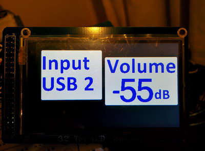
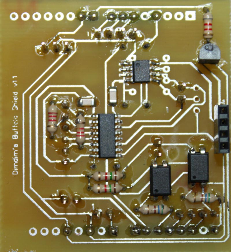
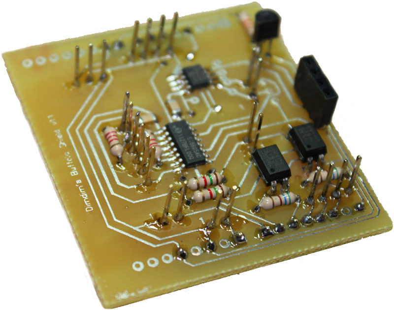
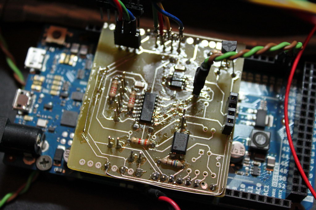
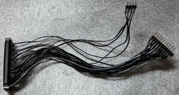
The finished assembly should look something like this:

finished_cable_1

What you need:
– An old 40 pin IDE cable. If you can’t get your hands on a ready-made IDE cable, you will need to find some 40 pin ribbon cable and a 40 pin connector (you can find it as “IDC40 IDE FEMALE CONNECTOR”) so you can roll your own. You will also need a small vise to press the connector.
– A 2×13 (or larger) pin header.
– A 1×4 (or larger) pin header.
– Some heat-shrink tubing.
– A soldering iron, etc.

We will be connecting only the wires necessary for operating the TFT as a display, so no SD card reader or touchscreen. You should keep that in mind.

Also, this cable only works with the Due, since it uses 3.3V logic. In order for it to work with the MEGA, 10K resistors should be connected in series with all the signal cables (except of course for the Vcc, LED-A and GND lines).

Let’s begin.

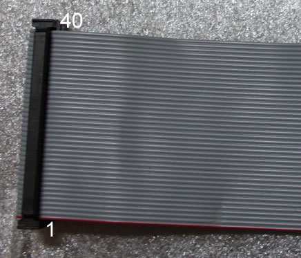
You start by cutting your IDE cable to the necessary length (or in case you’re making your cable from scratch, using as much ribbon cable as you need). The connectors on most IDE cables have one of the pin holes blocked, so you should use a small drill to open it up.

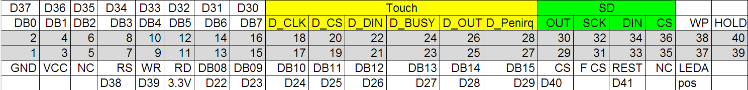
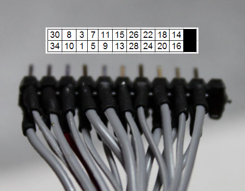
The pin numbering always starts from the red wire, so it goes like this:

IDC40_pin_numbering

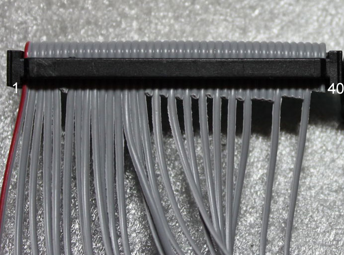
I prefer to cut off the unnecessary wires. This way there is less clutter, plus it is harder to get confused. Once the unnecessary wires have been cut off, we are left with this:

IDC40_pin_numbering_2

So this is one side of the cable. On the other side we will solder on to these:

pin_headers_1

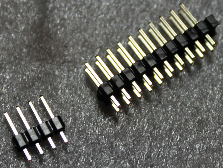
They are two pin headers. The 1×4 one is for LED backlight, Vcc power, RD and ground respectively. That corresponds to these pins:

pin_headers_3

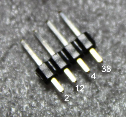
Finally, we have the 2×11 pin header. We need to make these connections:

pin_headers_2

The numbers are obviously pin numbers that correspond to the 40-pin ribbon cable. It should be pretty easy to get them right.

You should use heat-shrink tubing in order to insulate the connections, as well as improve the mechanical properties of the connections.

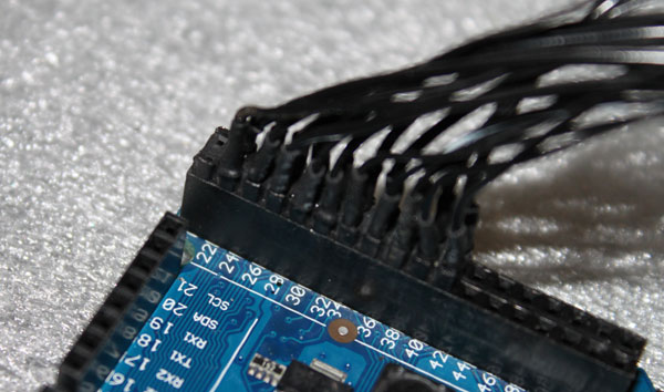
You will notice that the header is missing two pins (on the far right). That is done on purpose, to make it easier to align with the Due’s connector:

2x11_on_Due

And here is the finished cable, connected to the TFT as well as the Due. Note that it’s up to you to connect the 1×4 header whichever way you can.

Due_and_TFT

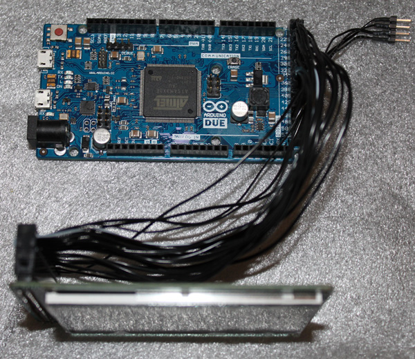
Notice that the ribbon cable is coming out of the IDC connector and going to the right, and not to the left. Should you connect it the wrong way, it is very likely that the TFT will be damaged, so be carefull!

You should also solder/jumper these pads (J1) on the back of the TFT:

TFT_J1

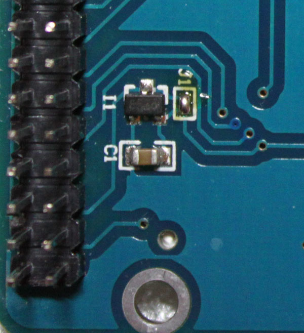
We have to do this since we are already powering the TFT with 3.3V. This way the local regulator will be bypassed.

That’s it! Good luck..

TFT HiFiDuino: Phase 1 complete!

It took quite a bit longer than I had expected but I am happy to report that Phase 1 of the TFT HiFiDuino project is complete.

v.1.00_screenshot_1_800x471

The objectives of Phase 1 were the following:
– Have full control over the parameters of the ES9018 chip. Essentially be able to write to all of the useful registers.
– Be able to have full IR remote control functionality.
– Be compatible with both the MEGA as well as the Due Arduino boards.
– Be able to switch between all 8 of the supported s/pdif inputs, as well as between I2S sources (USB in my case).
– Develop an Arduino shield that would simplify the wiring of the thing as much as possible as well as provide galvanic isolation between the Arduino and the DAC board.

All of these objectives have been accomplished, so here is v.1.00 of the code: TFT HiFiDuino v.1.00 (4484 downloads ) (Update: there is a new version available! Click here for the latest version.)

If you happen to come across a bug, please let me know by posting a comment below.
Feel free to use it whichever way you see fit, modify it, redistribute it, whatever, as long as you do not profit from it.

Requirements:
UTFT Library
– Fonts (included in the ZIP)

I will also make available the schematics & PCB for the shield, although it is not really necessary for operation of the controller.
Here is a preview:
Arduino_Shield_v.1.1_1_800x872

Arduino_Shield_v.1.1_2_800x630

3.2″ TFT pinout & connection to Arduino MEGA (or Due)

UPDATE (30/11/2013): Here is an easier way: https://www.dimdim.gr/2013/11/3-2%E2%80%B3-tft-connection-to-arduino-due-update/
Still, keep in mind that the info posted below still applies and is probably useful..

I’ve been asked what is the correct way to wire a 3.2″ TFT to an Arduino MEGA (or Due) in order to make it work with the UTFT library.

The answer of course depends on the exact model of the TFT that we have on hand. The below instructions apply to a generic 3.2″ TFT with wide aspect ratio and resolution of 240 x 400 that I got off of Ebay.

This is its pinout according to the manufacturer:

3.2-tft-pinout-pdf

This is nice, but I want to use a standard 40-pin ribbon cable which I have left over from an old computer, and its conductor numbering is a little different. At first I thought I’d try to make sense of it as I went but it didn’t take long for me to realize that it would actually save me time if I made a “conversion table”. So I came up with what you see here:

3.2-tft-pinout-xlsWhat we have here is the actual conductor number in the grey background (counting the conductors in the ribbon cable from left to right) and then above and below them the corresponding signal lines according to the above pinout. Above and below the signal lines I have noted the actual Arduino pins that correspond to the signals.

For example, pin 2 (the second pin on the flex cable looking at it from the left) corresponds to the DB0 signal which should be connected to the D37 pin on the Arduino MEGA (or Due). Note that the connections are made according to UTFT’s documentation and are applicable specifically to UTFT.

So we have to connect signals D0 through to D15 to the necessary digital pins. Then we also have to connect pins RS, WR, CS and REST to whichever pins we like (we must declare these pins in our sketch, see UTFT documentation). Pin 11 is RD and it must be pulled high, which means connecting it to +3.3V.  Pin 37 is the backlight illumination which means it must also be connected to +3.3V. This leaves pin 1 which must be connected to ground and pin 3 which must be connected to Vcc which in our case is 5V.

Note that I have not really gotten around to using the touchscreen capabilities or the SD reader, so I have not connected them to my Arduinos. It shouldn’t be difficult though.

Now, there is one more thing that I should point out and it is very important. The Arduino MEGA is using 5V logic while the TFT is expecting 3.3V logic. This means that if you connect the D0-D15 and RS, WR, CS, REST lines directly to the MEGA you will most likely damage the TFT. You need to connect a 10K resistor in series with each and every one of the lines. That will bring the voltage down to acceptable levels. Do not forget to do this!

In case of the Due the resistors are not necessary since it uses 3.3V logic so it is directly compatible.

Here is a little video I made of the 3.2″ TFT running a UTFT demo sketch:

Good luck!