Soekris dam1021 ArDAM Project update

Three weeks back I released the first public alpha of the ArDAM code, stating that it was very very alpha. I was meaning every word of that sentence.

Since then, Soren has released the new firmware for the DAM and I have resumed work on the project. Today I am happy to release the first usable version of the code (v0.74):  ArDAM1021 Code (68074 downloads )

ArDAM1021-v0.74-2

Changes include but are not limited to:

  • Tons of bugfixes (volume control, source selection, etc etc).
  • Filter selection either by remote or via rotary encoder (in the settings).
  • Option of displaying white text & graphics on black background as well as the “original” look.
  • New encoder code (it requires a new library).

The download now also includes all the necessary fonts. Let me know what you think.

The project’s page will be edited later today.

Universal Signal Isolator shield for Arduino DUE & MEGA

A few years back I designed a little Arduino shield who’s main function was to provide electrical isolation between an Arduino and a DAC (specifically a TPA Buffalo III).

The years have passed and my needs have changed with the introduction of the dam1021 DAC and its serial interface. My first though was to design a new shield specific to the dam but then I said “why not design a universal isolator shield?”. It would provide electrical isolation for both I2C as well as serial signalling.

Thus was born the Universal Signal Isolator shield for Arduino DUE & MEGA:

v0.97_crop

OK, it does look a lot more complicated than my first shield but remember, you only need to solder in the parts that your DAC actually needs.

So, what does this thing do?

1) Electrical isolation of I2C signals, complete with support of 8 isolated inputs or outputs (via an MCP23008 IC). Three of the MCP’s pins are high current outputs (up to 100mA).

2) Electrical isolation of up to 2 serial ports (implemented with an Si8642).

3) Electrical isolation of the second I2C interface of the DUE (implemented with an ADUM1250).

4) Powered either by 5VDC, 8-15VDC (non-regulated) or 7-12VAC (includes support for on-board rectification and filtering).

5) Support of a 5VDC power relay (up to 100mA).

6) Header for connecting a Nextion display.

7) On-board EEPROM memory (24LC256).

8) And of course full compatibility with the previous shield (same pinouts for the encoders, IR, TFT, etc.).

I will release the Eagle files once I have confirmed that the shield works as expected (I’m waiting for the first (and hopefully last) batch of PCBs).

Soekris dam1021: First major firmware update

A few hours ago Soren released the much-anticipated new firmware for the dam1021: http://www.diyaudio.com/forums/vendors-bazaar/259488-reference-dac-module-discrete-r-2r-sign-magnitude-24-bit-384-khz-328.html#post4421518

According to Soren, these are the changes to the firmware:

* PLL Clock Sync at sample rate change cut down to less than 0.2 second
* Isolated Serial port now works, note that port is at 3.3V cmos level
* Serial Port now interrupt driven, no character loss at high speed
* Volume Control now is -80db to +10 db, and phase bug fixed
* Volume Control also now have zero crossing detect
* Power Off plop can be reduced to 1/3 by adding a single 27K4 resistors, see picture attachment
* FIR1 filters doubled in size, so max 2032 coeff @ 44K/48K, 1016 @ 88/96K, 508 @ 176/192K, 127 @ 352/384K
* You can now select four sets of filters, named Linear, Mixed, Minimum and Soft.
* FIR1 coefficients are now 1.31 format, filters should be good down to around -150 db
* Stock filter now have improved deemphasis filter
* Input Source Select bug fixed
* New mode setting: Normal, Inverted, Balanced Left, Balanced Right
* The tiny bug on signal saturation on -full scale fixed
* Should now be possible to do balanced and crossovers by parallel the inputs and connecting the isolated serial ports together, more details to follow

I had some difficulty uploading the new firmware but that was due to Windows 10 and ExtraPuTTY not playing along very well. I got an “Error File not found!” message when I was trying to upload the file. When I went to a Windows 8.1 machine everything went as expected. One thing – do not forget to give the “update” command once you have uploaded the code followed by a “y” and return. When the procedure is complete and upon power cycling the board (and entering the “+++” command) you should get something like this:

soekris after upgrade crop

Both the uManager and FPGA revisions should be 0.99.

The uManager has a few new options:

soekris after upgrade 2 crop

Plus these are the new built-in filters:

soekris after upgrade filters all crop

First impressions are very good. The dam now locks much faster to incoming signals, so fast that it’s near instantaneous:

Plus we have very good news on the serial control department. Not only has the isolated serial port been enabled (to be tested asap..) but the RS232 port seems to no longer have problems with my Arduino controller. It probably had something to do with the “Serial Port now interrupt driven, no character loss at high speed” fix. So development of the ArDAM1021 code becomes high priority. 🙂

Zero crossing detection seems to be working fine too – no more glitches during volume adjustments.

All in all I would say this is a pretty good upgrade. Kudos to Soren.

Now looking forward to DSD support on the next upgrade.

Soekris dam1021 Arduino Control Code

A few days ago Soren announced that the release of the new firmware for the dam1021 was close.

In light of that announcement I have decided to release the Arduino code that I had written a few months back, even though it is not quite finished.

2015-07-31 18.15.44_res

I am doing this to help fellow Arduino & dam1021 enthusiasts in their quest of remote-controlled color TFT bliss.

So, for now, no real documentation – this is no polished piece of software, but it works (for the most part).

Since it is based on the TFT HiFiDuino code, you can get started by reading its documentation. It should not be hard to get started with this. The code itself also contains useful comments.

I should remind you that the dam1021 at the moment only “talks” real RS-232, meaning that a circuit that converts the TTL level serial port of the Arduino to a real RS-232 port is necessary.
However, we were promised that with the firmware upgrade the second, isolated TTL serial port would be enabled, so here’s hoping..

Also, I have come across a strange problem with the serial communication with the dac. In the beginning all is well but after a while the dam no longer responds to the commands that are sent by the Arduino. However, it (the dam) is still sending data back to the Arduino – when the sampling rate changes, the new SR is displayed properly on the TFT.

I have verified that the Arduino is indeed sending the commands to the dam:

DS1Z_QuickPrint21

DS1Z_QuickPrint22

I hope the problem gets sorted out in the new firmware release.

Anyway, here is the code: ArDAM1021 Code (68074 downloads )  The project also has its own page: https://www.dimdim.gr/arduino/ardam1021-project/

Let me know what you think. I promise to put more work into it in the next few weeks..

@ the Beach Bar, Vol. 6 (Parts 1 & 2) (July 2015)

This is a special 2-part extended edition of the @ the Beach Bar Series.

Greece may be in deep trouble, but we should not let that bring us down.

No matter what the outcome of today’s referendum, we remain United and Strong!

Part 1:

At The Beach Bar Vol. 6 (Part 1) (July 2015) by Dimitris Dimitrakoudis on Mixcloud

Tracklist:
1. Synapson feat. Victor Deme - Djon Maya Mai (Original Mix)
2. Tensnake ft. Nile Rodgers and Fiora - Love Sublime
3. Bipolar Sunshine - Daydreamer (Gryffin Remix)
4. Compuphonic feat. Marques Toliver - Sunset (Aeroplane Remix)
5. Angelika Dusk feat. Playmen - Beautiful Love
6. The Avener feat. Ane Brun - To Let Myself Go
7. Σtella - Picking Words
8. Hercules & Love Affair - Do You Feel The Same (Purple Disco Machine Remix)
9. Luis Leon - Love Is A Lie (Original Mix)
10. Matvey Emerson feat. Rene - Lights (Anton Ishutin Remix)
11. Soul II Soul - Back To Life (KLATCH's Back To Reality Remix)
12. Sante Cruze - Get So High (Original Mix)
13. Matvey Emerson feat. Rene - Alright (Original Mix)
14. Maxxi Soundsystem feat. Name One - Lone Raver (Original Mix)
15. Claptone - The Music Got Me (Original Mix)
16. Thee Cool Cats & Lika Morgan - Thee Worst (Club Mix)
17. Nathalie West K - Desire (Original Mix)

Part 2:

At The Beach Bar Vol. 6 (Part 2) (July 2015) by Dimitris Dimitrakoudis on Mixcloud

Tracklist:
1. Malikk - Just Listen (Original Mix)
2. Lorde - Yellow Flicker Beat (2nd Room Remix)
3. Moe Turk feat. Sanna Heartfield - Plan (Original Mix)
4. TWAN Collective feat. Elena - Back to You (Original Mix)
5. Ben Delay - I Told You (Giom Remix)
6. Millok + New5ense - Let It Go (Original Mix)
7. Mark Lower feat. Scarlett Quinn - Like a Prayer (Original Mix)
8. Thee Cool Cats - Man Of The Year (Original Mix)
9. Phunk Investigation - Extasy (Cristian Poow Remix)
10. Escape - Just Escape (Justin Martin Remix)
11. Sharam Jey, West.K - Stay (Original Mix)
12. Serge Devant & Damiano feat. Camille Safiya - Fearing Love (Club Mix)
13. KORT feat. Reno Ka - Stay (Original Mix)
14. Flutters - Those Days Are Over (Mark Lower Remix)
15. Shit Hot Soundsystem - Charlotte
16. Cari Golden, DJ T. feat. Cari Golden - City Life (Maceo Plex Remix)
17. Zimmer x Pallace - Saturday Love
18. Tapetenwechsel - Feel You (Original Mix)
19. Sean Finn, Tinka - Summer Days (Ben Delay Remix)

New section: Στα Ελληνικά..

No, it is not a Greek version of my blog (sorry..).

Even though I am Greek, I chose to publish this blog in English. I made that choice because I believed that its target audience would be better served this way.

Since then I have realized that I would need to occasionally post some information in Greek, and thus came to be the Greek section.

Its first page is a guide to installing the Arduino IDE for novices: Εγκατάσταση Περιβάλλοντος Arduino Για Αρχάριους

Universal USB to I2S Interface Indicator PCB

Over at avclub.gr we designed a custom PCB to ease the implementation of the Universal USB to I2S Interface Indicator. It was a joint effort between myself and Manolis (a.k.a. lemon at avclub.gr). I did the circuit design and Manolis did the PCB design work.

This is the schematic of the final version of the circuit:

USB2I2S schematic 0.8b

When the PCB design was finalized, a GB was organized. When the GB was finished we placed an order on seeedstudio.com’s Fusion PCB service. About 3 weeks later the PCBs had arrived:

IMG_9927

PCB_from_fabThe production quality was truly excellent.

From top to bottom we have:

  • H1: Header for power. It may be either 5VDC (regulated) or 7-12VDC (non-regulated). Pin 1 is 7-12VDC, Pin 2 is GND, Pin 3 is 5VDC.
  • H2: OLED display connector. Pin 1 is 3.3V to the display, Pin 2 is GND, Pin 3 is SCL, Pin 4 is SDA.
  • H3: Header for future expansion. It exposes the unused I/O of the Nano in case it may be of use in the future. The last two pins are buffered by transistors so that they can supply enough current to engage small relays (5VDC, up to 100mA per pin). Pin A7 is connected to JP1_IR as well (see below).

Next up is the socket for the Arduino Nano. You will notice that the USB port should be on the right.

At the bottom of the board we have:

  • JP1_IR: This is a connector for an IR Receiver module. Software support for this is currently in beta. Pin 1 is signal out, Pin 2 is GND, Pin 3 is power (5V). Note that R4 and C5 provide filtering for the power and should be installed. R5 is an optional pull-up resistor. It should not be installed for normal use.
  • H4: This is the “dirty” side of the U1 isolator. Pin 1 is Vdd (usually 3.3V or whatever your USB Interface module uses for its logic levels). Pins 2 through 7 are inputs and Pin 8 is GND.
  • H5: This is the “dirty” side of the U2 isolator. Pin 1 is Vdd (usually 3.3V or whatever your USB Interface module uses for its logic levels). Pins 2 through 5 are inputs and Pin 8 is GND.

Note that in the future a Si8642BA may be used in place of U2. With proper support from the code that will turn 2 of the 4 inputs into outputs, so that they may be used to control a DAC board (for example to select an input).

This is the full BoM:

Part Description
FB1, FB2, FB3 Ferrite Bead 0805
R1 2.7K 0805
R2, R3 8.75K 0805
R4 100R 0805
R5 10K 0805 (optional)
C1, C2, C3, C4 100n X7R 0805
C5 10uF 10V X7R 0805
Q1, Q2 BC808 or equivalent SOT-23
U1 Si8065AA-B-IU
U2 Si8045AA-B-IU (optionally Si8642BA-B-IU)

In case you want to have your own PCBs made, these are the Gerber files: Universal USB to I2S Interface Indicator PCB Gerbers (5297 downloads )

You will also need an Arduino Nano, a suitable OLED display and some cables, connectors, etc. (see project page).

As soon as I received the boards, I built a prototype with whatever components I had lying around (thus the wrong size of most of the resistors & capacitors).

Prototype PCB

And proceeded to test it out with an Amanero Combo384 board:

Everything worked as it was expected. 🙂

At the moment this board (and relevant Arduino code) has been tested with the following USB to I2S interfaces:

Amanero Combo384
hookup_amanero_v2Note that R1 should be installed for proper operation.

DIYINHK XMOS
hookup_diyinhk_xmos_v2

JLSounds I2SoverUSB
hookup_jlsounds_v2

Luckit WaveIO
hookup_waveIO_v2
You will notice that there is no Vcc pin on J9. In order to power the isolator, we will have to “steal” power from elsewhere on the board. A good place to tap is the power pin of the on-board I2S isolator, just to the left of the I2S LRCK U.FL:
hookup_waveIO_power

Amiga 600 recapping

The Commodore Amiga 600 was a force to be reckoned with when it was released back in 1992. It was a low-cost but very capable gaming machine. That is why it still has a loyal following.

A friend of mine belongs to the vintage gaming crowd and as such is the proud owner of an A600. Unfortunately for him, eventually his A600 gave out. After some googling he came across a number of A600 owners who have had the same problem with their units. Most of them were able to bring their machines back to life by replacing the electrolytic capacitors of the mainboard. A “re-capping kit” is relatively low-cost so my friend went ahead and ordered one. When it came he took his machine and paid me a visit.

The re-capping process ended up taking a lot longer than I had expected, but that was due to my inexperience with the specific machine. In the process I gathered a lot of information that may be of use to others, so here goes.

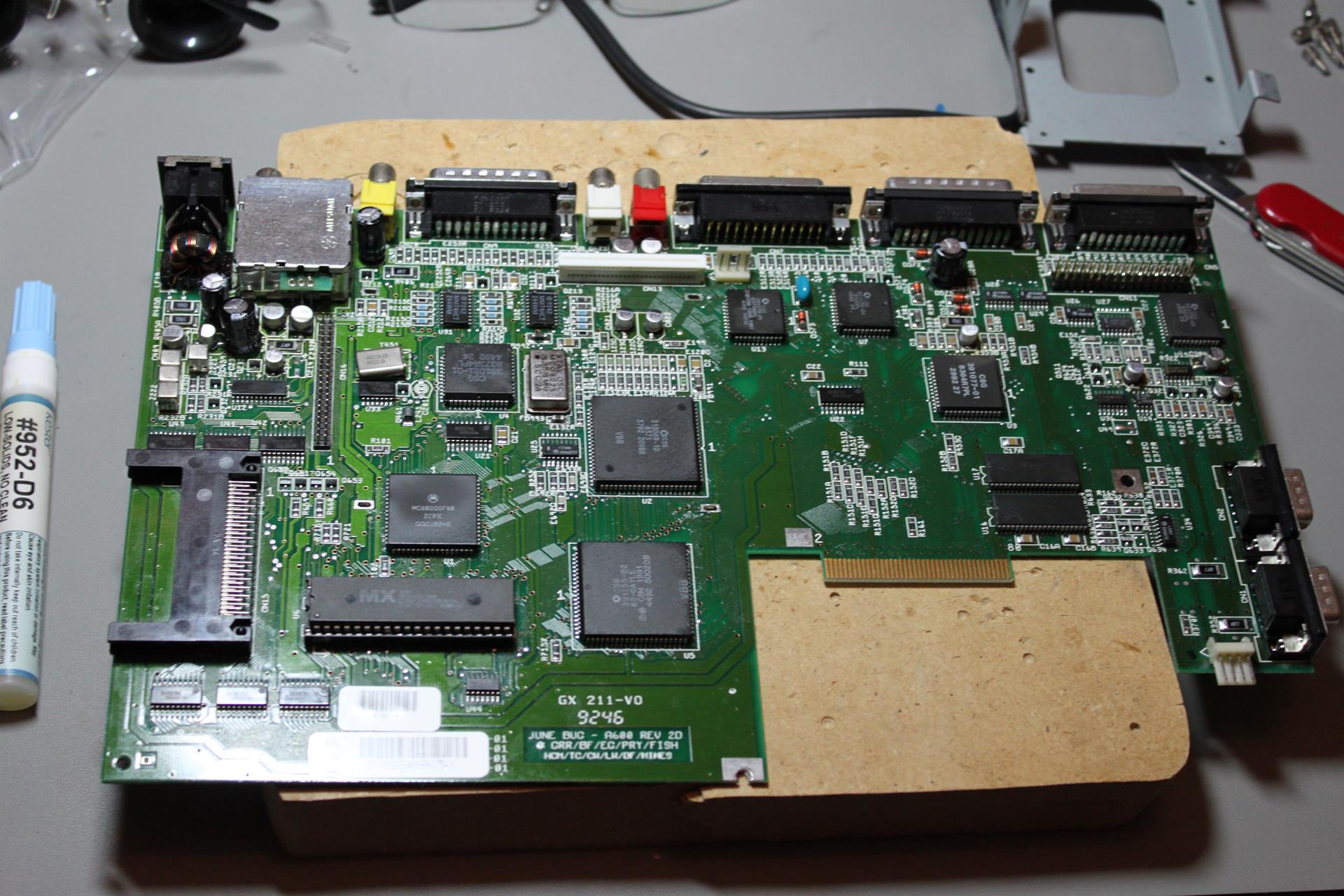
The first step is opening up the case. You do that by removing the screws on the underside of the machine and then carefully popping it open. There are a number of plastic clips on the inside of the case that need to be pried open with care. You can see a few of them in this picture (top part):

A600_open

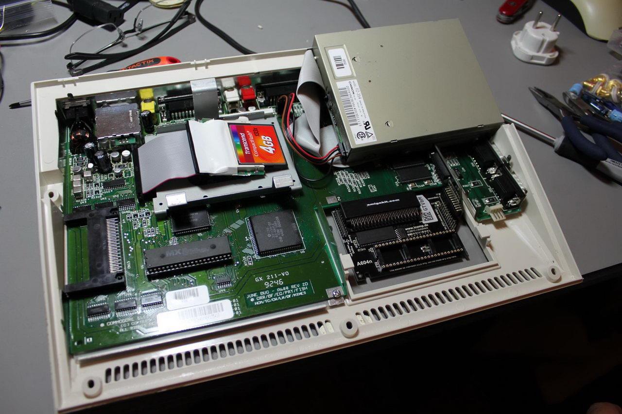
Looking at this picture you will also notice that my friend has put in a 1MB RAM upgrade as well as an HDD emulator (the 4GB flash drive).

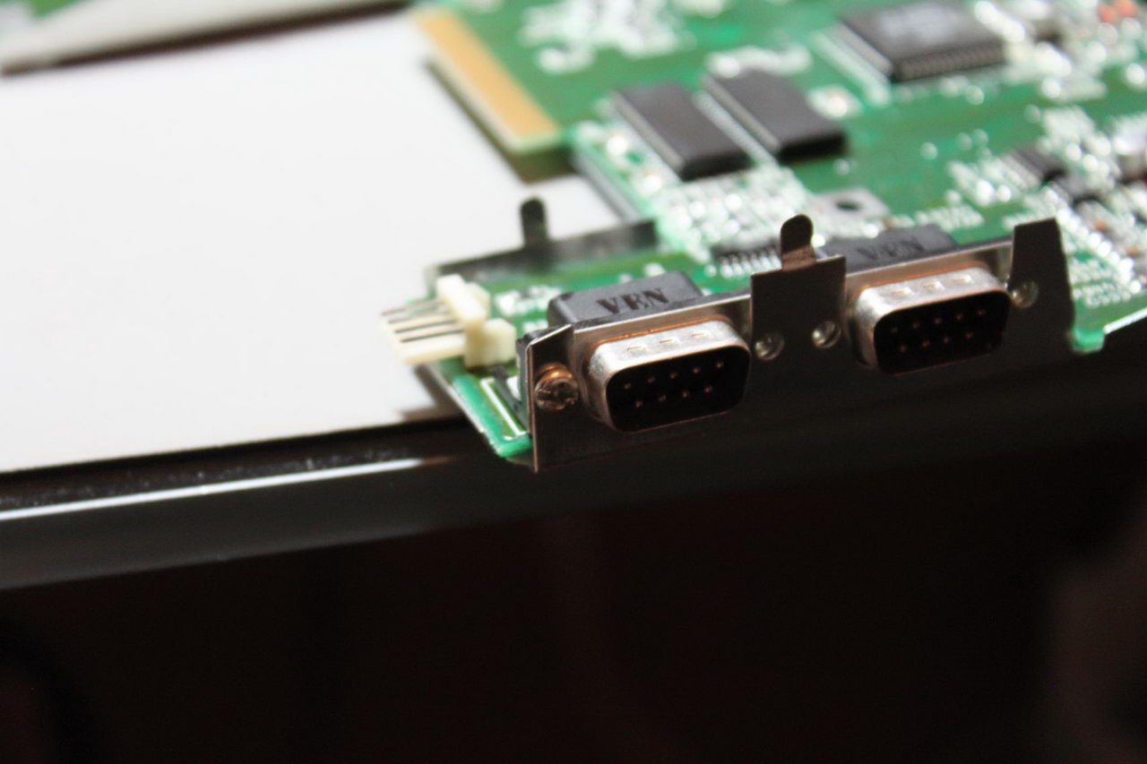
After you have opened up the case you need to remove the mainboard. To do that you have to remove the one screw visible on the lower edge of the mainboard. After that you must lift the mainboard along with its metal shield from the right side, clearing the two ports. You will need to use a little force. Be careful – these plastics are over 20 years old and thus do break easily. When you have cleared the right side you pull the board towards the front of the case and then up so as to clear the rear connectors. Now you have removed the board from the plastic case.

Now you need to separate the mainboard from its metal shielding. To do that you take out this pesky little screw:

Mainboard_screw

Then you have to unscrew the hex screws on the rear connectors. There are 8 of them in total. I haven’t taken a pic of them but they are pretty easy to spot.
Now all you have to do is bend out of the way the little pieces of metal that are situated around the shield, like this one:

metal lug

Assuming all has gone well, you should have the mainboard out and be ready to start the procedure.

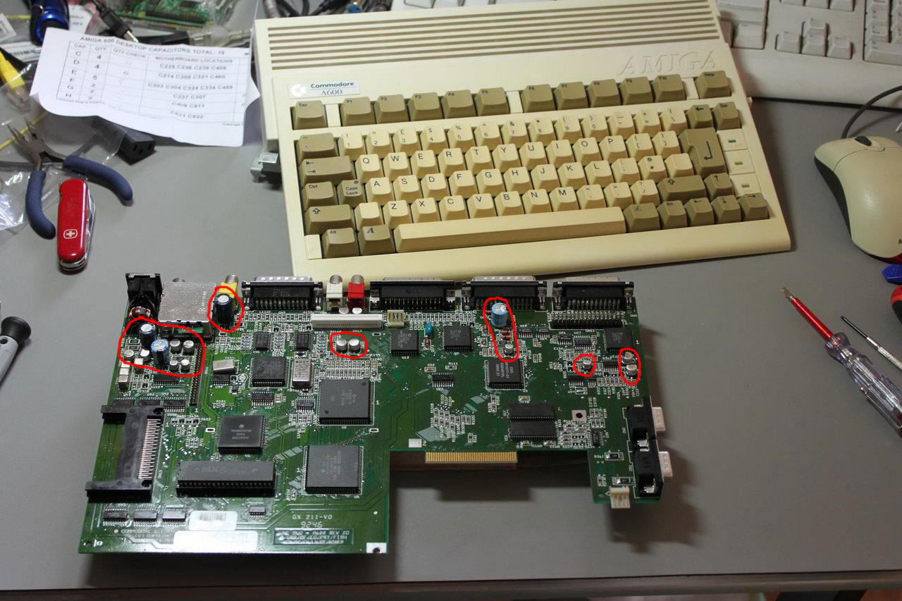
There is a number of caps that need to be changed. There are 4 through-hole components and a number of SMD parts.

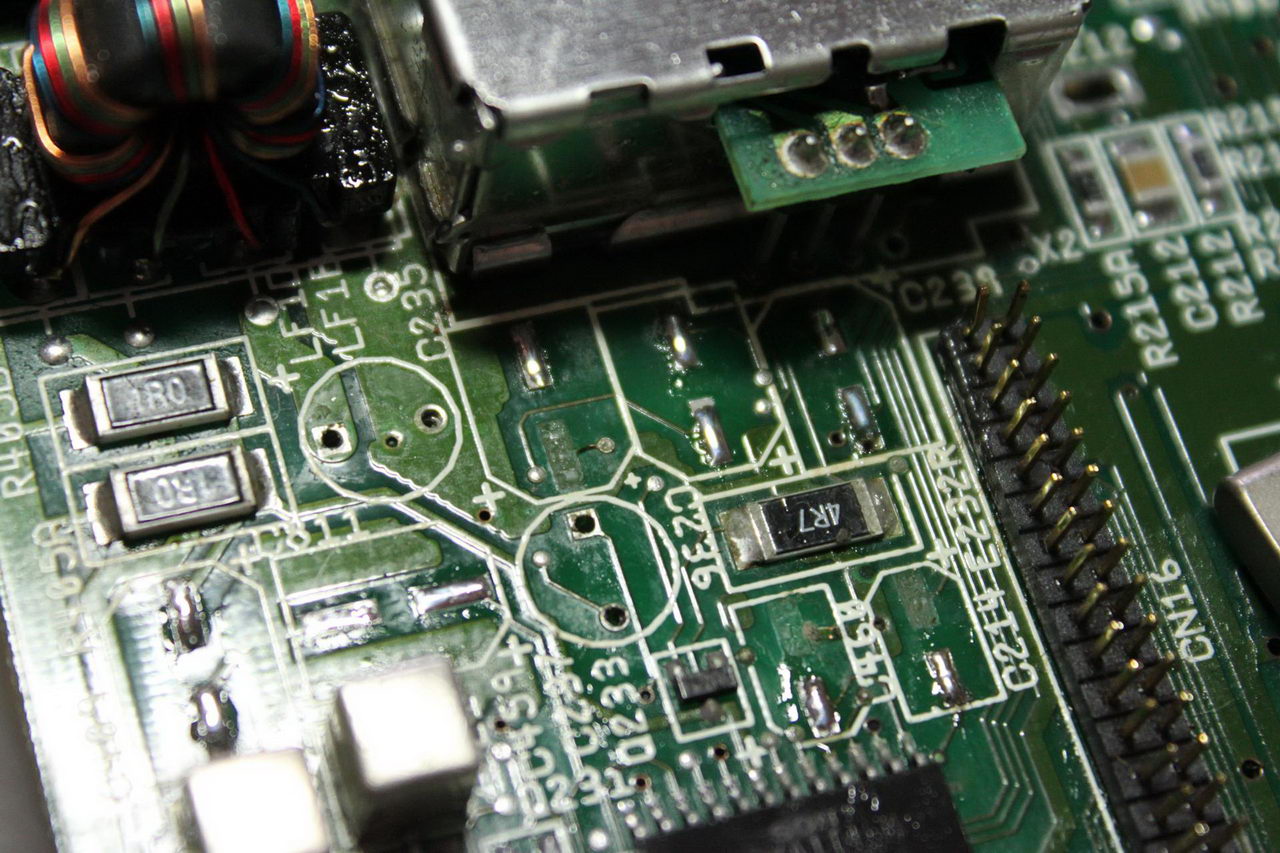
I have circled the offending caps in this pic:

MB_out_marked_caps

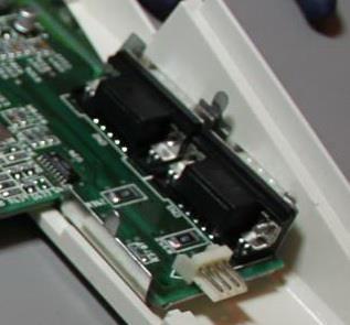
Some people choose to also change the two caps located on the back of the audio out ports. These caps are just DC blocking caps, they are not to blame for the death of the machine. Plus, they are located in a very tight spot, making replacing them too risky of a procedure.

So, first I took out the through-hole parts. That was relatively easy. Just bear in mind that you will need a relatively powerful soldering iron since the (-) sides are soldered to the ground plane which is extremely efficient at sinking heat.

Next up were the SMD parts. I had desoldered SMD caps in the past with no difficulty using a regular soldering iron but these ones proved to be particularly nasty. My first attempt ended in me pulling out one of the solder pads. I said to myself “bad luck.. whatever..” and moved on to the next cap. You guessed it – the next one also had the same luck. At that point I decided to change strategy and go with the hot air rework station. It proved to be much better at desoldering the old caps. For some reason even with the hot air I managed to pull off one SMD pad.

after_left_caps

So now I had 3 caps missing pads. That is considered bad. I decided to go to the schematics and see if I could get away with not replacing the specific caps. It turns out that I was lucky. The rightmost cap (C214) is a DC blocking cap that sends the summed L+R audio to the RF encoder IC. Since my friend does not (and will never) use the RF modulator, it was OK to not care about this cap.

I was not so lucky with the next one, C460. This cap is used to bypass the U12 IC, which I’m afraid is actually necessary for proper operation of the board. So I had to get creative. The missing pad corresponds to the GND connection, so I thought I would just solder some wire from the bottom of the cap to a nearby GND point. It turned to be much easier than that. I scraped the green lacquer from the remaining trace and managed to solder the capacitor to that by turning it a bit. In other words, I got lucky.

With the third cap (C235) I did what I did with the second one – scraping off the lacquer and soldering at a small angle. After I had done the procedure I remembered to look at the schematic to see what it was for – it turned out that I could have gotten away with not installing it since it was also a DC blocking capacitor, this time from the encoder IC to the RF modulator module. Oh, well..

When I was done the board looked like this:

Finished

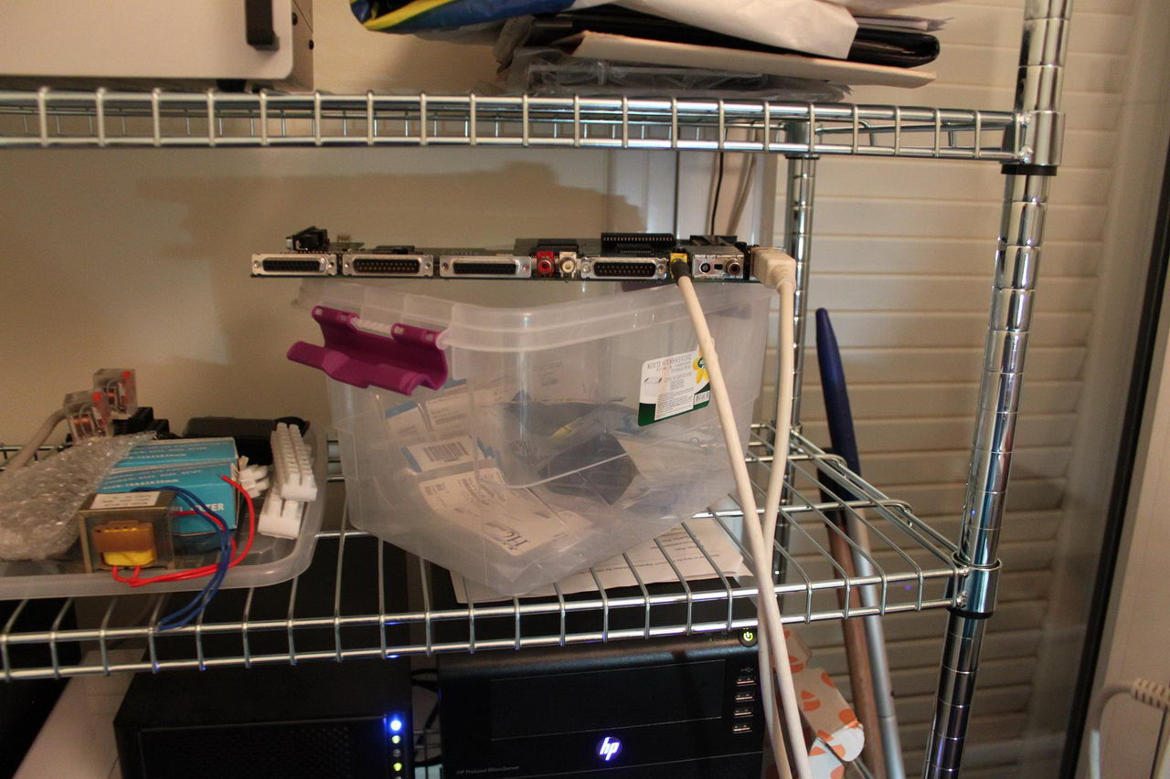
This was the moment of truth. We hooked up the board to its power supply and my (very bare) test display.

Testing

We plugged in the power and voila! The Amiga 600 lives! 🙂

Boot

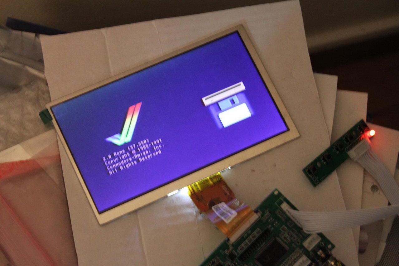
We then proceeded to put the machine back together and do another test, this time with the HDD installed. As was expected, everything was working just fine:

Boot_2

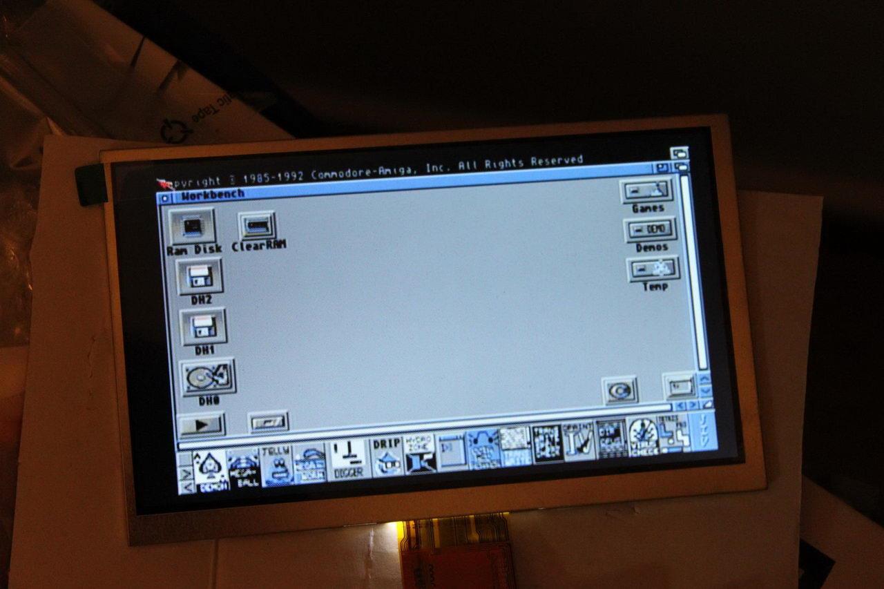
So, there you have it. An (almost) fully re-capped Amiga 600. My friend is in for some serious gaming. 🙂

Universal USB to I2S Interface Indicator feature upgrade

Following up on a number of feature requests made over at avclub.gr I made a few rather interesting additions to the code:

1) The OLED display will show the type of signal (PCM or DSD) for 3 seconds if a change in signal type occurs. Only supported on USB interfaces that support it (obviously).

2) IR remote control support via the well-known IRremote Library. Support for power on/off and source selection (S/PDIF or USB).

3) The OLED display will display the name of the selected source, permanently if it is S/PDIF or for 3 seconds if it is USB.

More details on the new features will be added to the project’s home page, as will the new version of the code.

Here is a short video of the prototype in action:

Soekris R-2R: Damaged isolator fix

A friend of mine had a little accident with his DAM1021 which resulted in him frying the on-board isolators.

We are talking about these three ICs, with part number “SI8620BB-B-ISR”.

IMG_9719

It turns out that the specific ICs are at their End Of Sale, so both Mouser and RS did not have them in stock. Luckily, it turns out that the TI ISO7420FEDR is a good alternative. Unfortunately, it is also about 2.5 times the price of the Si part, but what can you do.. The order was placed, in time the ICs were delivered, and it was time to do the work.

This is what my workbench looked like:

IMG_9717

You see the DAM board, a collection of different width Capton tapes, the ISO7420FEDR ICs and my favorite set of tweezers. In the far right you see part of my magnifying glasses. They are necessary for repairs of SMD stuff.

What you don’t see is my hot air rework station which is also necessary.

First I had to use Capton tape to cover the “innocent” components close to the isolator chips. The hot air could damage them if I was not careful.

IMG_9721

Using the hot air rework station, I desoldered the offending ICs:

IMG_9723

And using my normal soldering iron I managed to solder in the replacement ICs:

IMG_9727

It may not look as good as the original solder work, but the board is now as good as new. 🙂