Fixing startup issues with Arduino DUEs

If you’ve had a lot of Arduino DUEs go through your hands (or if you are just unlucky), chances are you’ve come across at least one that does not start-up properly.

The symptom is simple: you power up the Arduino but it doesn’t appear to “boot”. Your code simply doesn’t start running.

You might have noticed that resetting the board (by pressing the reset button) causes the board to start-up normally.

I had come across such a board a while back, and had thought to myself “cheap generic, probably faulty” and had just put it aside. At ~13€ it was no big loss.

A few days ago a fellow tinkerer (thank you Alex!) alerted me to a fix for this problem.

It appears that the problem was first spotted on Freetronics’ forum and was dealt with swiftly.

The problem occurs only on some DUE boards and is due to some undocumented behaviour of the ATSAM3X8E processor combined with the behaviour of some MOSFETS installed on the DUE boards. So its occurence is largely a matter of luck.

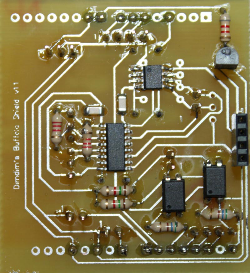
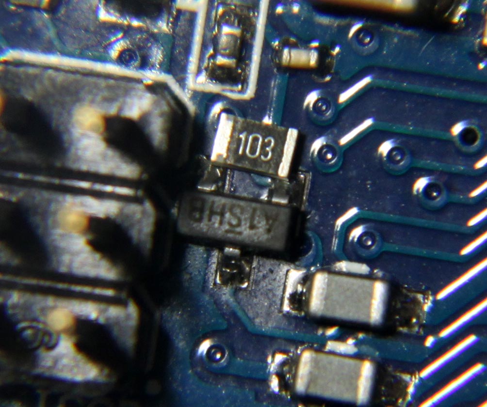
The fix is simple: you just solder a 10K resistor across the top of this mosfet:

DUE-Fix-culprit

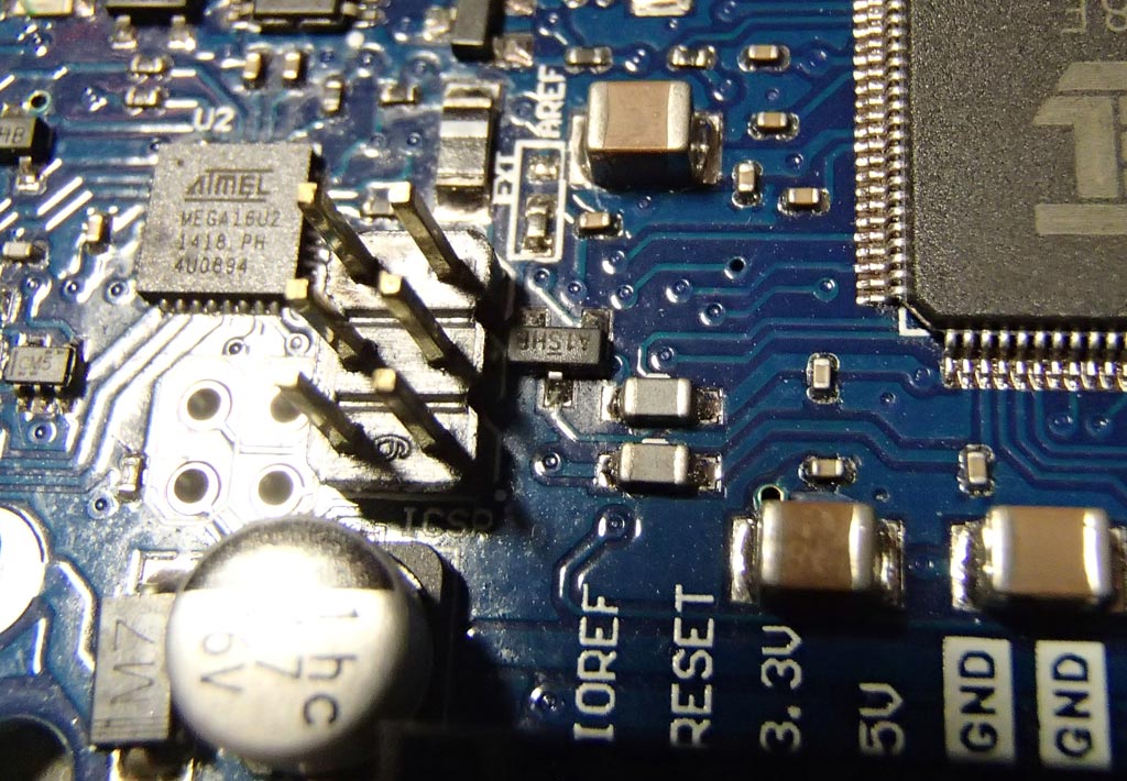
This is a 10K 0805 resistor that is about to be soldered:

DUE-Fix-1

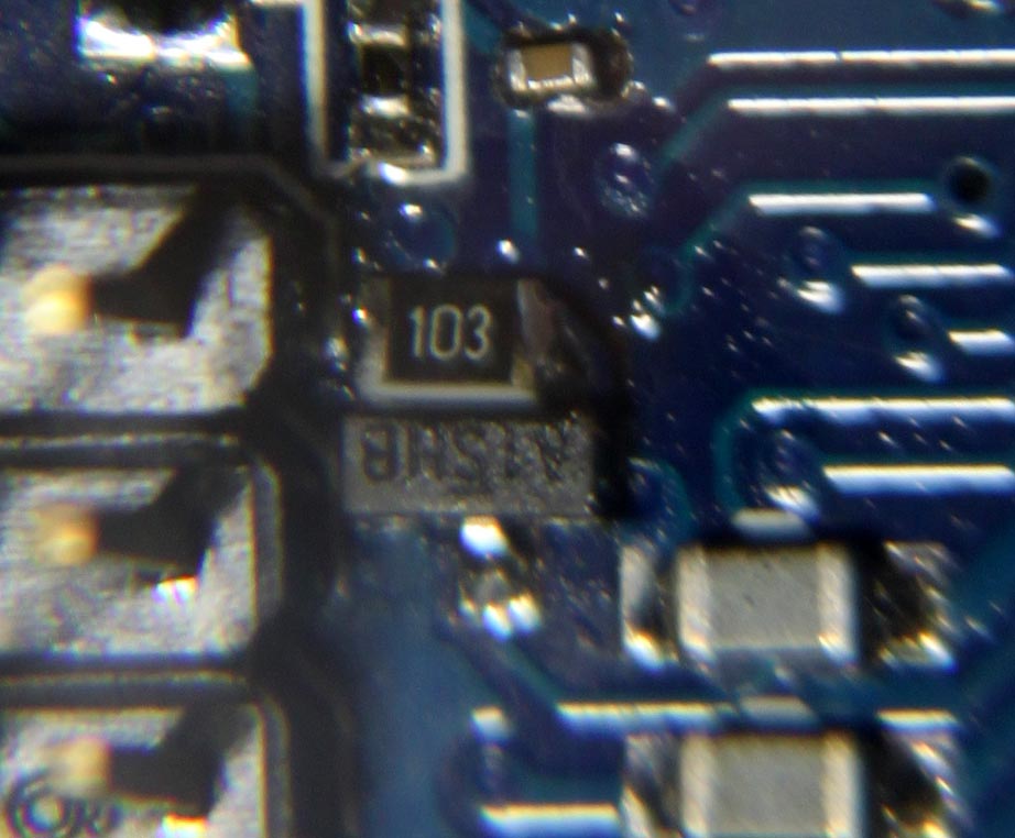
..and after soldering:

DUE-Fix-2

The discovery of the problem prompted a new revision of the reference design by the Arduino team.

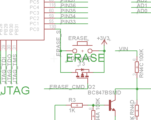
This is what the Rev 2’s relevant part of the schematic looks like:
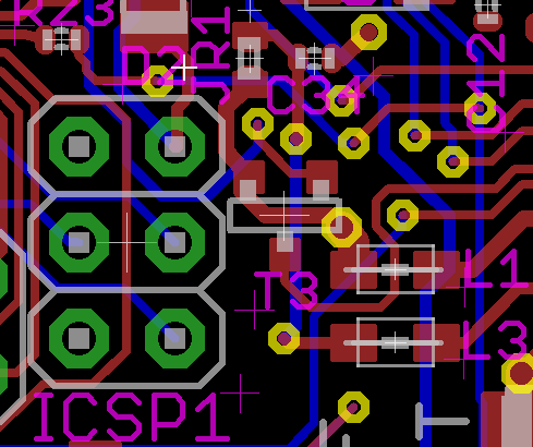
Arduino_DUE_Rev.2_sch

and the PCB:

Arduino_DUE_Rev.2

And this is what Rev 3 looks like:

Arduino_DUE_Rev.3_sch

Arduino_DUE_Rev.3

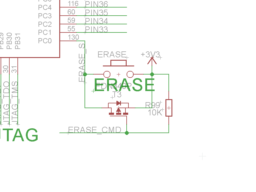
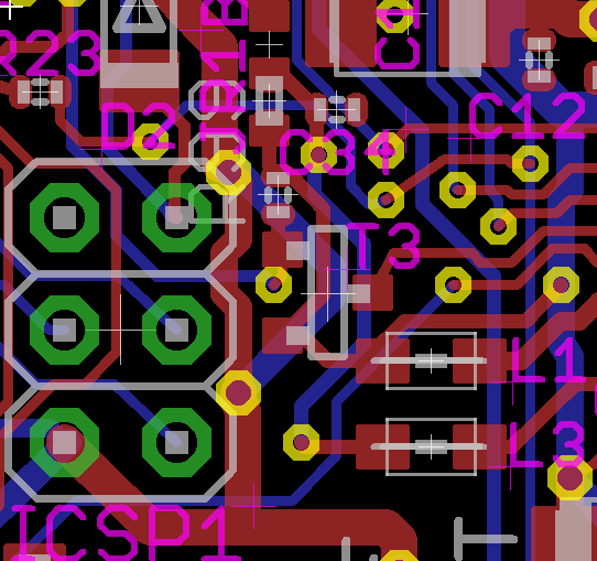
You will notice a new component, R99, plus the mosfet is now mounted vertically.

So, if you are shopping for a DUE, look for one with this mosfet mounted vertically, just to be on the safe side.

They’re here!

I’m talking about my new Universal Signal Isolator PCBs:

USI_bare_slanted USIs_bunch

IMG_0320_res

I built one to test it out and everything seems to be working as it should. Next step is a page for the project, with schematics, a BoM and build instructions.

It is compatible with the current versions of both the ArDAM1021 and TFT HiFiDuino projects.

For now you can find more info in this post.


Soekris dam1021 Arduino Control Code

A few days ago Soren announced that the release of the new firmware for the dam1021 was close.

In light of that announcement I have decided to release the Arduino code that I had written a few months back, even though it is not quite finished.

2015-07-31 18.15.44_res

I am doing this to help fellow Arduino & dam1021 enthusiasts in their quest of remote-controlled color TFT bliss.

So, for now, no real documentation – this is no polished piece of software, but it works (for the most part).

Since it is based on the TFT HiFiDuino code, you can get started by reading its documentation. It should not be hard to get started with this. The code itself also contains useful comments.

I should remind you that the dam1021 at the moment only “talks” real RS-232, meaning that a circuit that converts the TTL level serial port of the Arduino to a real RS-232 port is necessary.
However, we were promised that with the firmware upgrade the second, isolated TTL serial port would be enabled, so here’s hoping..

Also, I have come across a strange problem with the serial communication with the dac. In the beginning all is well but after a while the dam no longer responds to the commands that are sent by the Arduino. However, it (the dam) is still sending data back to the Arduino – when the sampling rate changes, the new SR is displayed properly on the TFT.

I have verified that the Arduino is indeed sending the commands to the dam:

DS1Z_QuickPrint21

DS1Z_QuickPrint22

I hope the problem gets sorted out in the new firmware release.

Anyway, here is the code: ArDAM1021 Code (54639 downloads )  The project also has its own page: https://www.dimdim.gr/arduino/ardam1021-project/

Let me know what you think. I promise to put more work into it in the next few weeks..

TFT HiFiDuino v2.01 + video

As is usually the case, a few bugs crept into the v2 release. So, here is v2.01: TFT_HiFiDuino_v2.xx (10515 downloads ) (Note: As always, the code on this page may not be the current one, i.e. there may be a newer version available. The latest version is always up at the project’s official page.)

Also, here is a video of the code in action:

TFT HiFiDuino v1.06

Here is version 1.06 of the code: TFT_HiFiDuino_v1.06b.zip (4719 downloads )
(11/12/2013: Update to v1.06b. Reason: minor bugfix)  (Note: As always, the code on this page may not be the current one, i.e. there may be a newer version available. The latest version is always up at the project’s official page.)

IMG_6903_fix_&_crop_res

IMG_6905_crop_res

The main difference is the support of Buffalo 3SE as well as an “always on” feature that bypasses the remote on/off sections of the code.

Here is the official change log:

– Compatible with Buffalo 3 and Buffalo 3 SE. Just comment out the relevant statement.
– Fixed “OS Filt” & “SR disp”.. They were not working correctly.
– Blue select boxes are gone.. they looked quite bad.
– Some other minor (mainly aesthetic) fixes..

A new revision of the shield is to follow (for improved B3SE compatibility).

TFT HiFiDuino: Phase 1 complete!

It took quite a bit longer than I had expected but I am happy to report that Phase 1 of the TFT HiFiDuino project is complete.

v.1.00_screenshot_1_800x471

The objectives of Phase 1 were the following:
– Have full control over the parameters of the ES9018 chip. Essentially be able to write to all of the useful registers.
– Be able to have full IR remote control functionality.
– Be compatible with both the MEGA as well as the Due Arduino boards.
– Be able to switch between all 8 of the supported s/pdif inputs, as well as between I2S sources (USB in my case).
– Develop an Arduino shield that would simplify the wiring of the thing as much as possible as well as provide galvanic isolation between the Arduino and the DAC board.

All of these objectives have been accomplished, so here is v.1.00 of the code: TFT HiFiDuino v.1.00 (4482 downloads ) (Update: there is a new version available! Click here for the latest version.)

If you happen to come across a bug, please let me know by posting a comment below.
Feel free to use it whichever way you see fit, modify it, redistribute it, whatever, as long as you do not profit from it.

Requirements:
UTFT Library
– Fonts (included in the ZIP)

I will also make available the schematics & PCB for the shield, although it is not really necessary for operation of the controller.
Here is a preview:
Arduino_Shield_v.1.1_1_800x872

Arduino_Shield_v.1.1_2_800x630

TFT Hifiduino Code v0.95

Update: TFT Hifiduino Code v0.95 available!

Download from here: B3_arduino_code_v0_95 (Note: As always, the code on this page may not be the current one, i.e. there may be a newer version available. The latest version is always up at the project’s official page.)

Here is a partial changelog:

– Changed rotary encoder code. Should work for MEGA as well as Due (no longer using interrupts).

– Added remote control codes for virtually all of the functionality that is offered by the encoder so now all of the parameters can be set via remote.

Bugs:

– Selection bar is still buggy. Haven’t gotten around to sorting it out.

Missing functionality:

– Disply backlight handling. It is next in line to be sorted.

– Sleep mode. Much research is needed, so won’t be implemented soon.

Also, I’m working on a simple MEGA / Due shield that should simplify things a lot. It is a work in progress, so I’m not ready to publish schematics or anything, but you can have a look at the current version’s 3D model:

Render_01

3.2″ TFT pinout & connection to Arduino MEGA (or Due)

UPDATE (30/11/2013): Here is an easier way: https://www.dimdim.gr/2013/11/3-2%E2%80%B3-tft-connection-to-arduino-due-update/
Still, keep in mind that the info posted below still applies and is probably useful..

I’ve been asked what is the correct way to wire a 3.2″ TFT to an Arduino MEGA (or Due) in order to make it work with the UTFT library.

The answer of course depends on the exact model of the TFT that we have on hand. The below instructions apply to a generic 3.2″ TFT with wide aspect ratio and resolution of 240 x 400 that I got off of Ebay.

This is its pinout according to the manufacturer:

3.2-tft-pinout-pdf

This is nice, but I want to use a standard 40-pin ribbon cable which I have left over from an old computer, and its conductor numbering is a little different. At first I thought I’d try to make sense of it as I went but it didn’t take long for me to realize that it would actually save me time if I made a “conversion table”. So I came up with what you see here:

3.2-tft-pinout-xlsWhat we have here is the actual conductor number in the grey background (counting the conductors in the ribbon cable from left to right) and then above and below them the corresponding signal lines according to the above pinout. Above and below the signal lines I have noted the actual Arduino pins that correspond to the signals.

For example, pin 2 (the second pin on the flex cable looking at it from the left) corresponds to the DB0 signal which should be connected to the D37 pin on the Arduino MEGA (or Due). Note that the connections are made according to UTFT’s documentation and are applicable specifically to UTFT.

So we have to connect signals D0 through to D15 to the necessary digital pins. Then we also have to connect pins RS, WR, CS and REST to whichever pins we like (we must declare these pins in our sketch, see UTFT documentation). Pin 11 is RD and it must be pulled high, which means connecting it to +3.3V.  Pin 37 is the backlight illumination which means it must also be connected to +3.3V. This leaves pin 1 which must be connected to ground and pin 3 which must be connected to Vcc which in our case is 5V.

Note that I have not really gotten around to using the touchscreen capabilities or the SD reader, so I have not connected them to my Arduinos. It shouldn’t be difficult though.

Now, there is one more thing that I should point out and it is very important. The Arduino MEGA is using 5V logic while the TFT is expecting 3.3V logic. This means that if you connect the D0-D15 and RS, WR, CS, REST lines directly to the MEGA you will most likely damage the TFT. You need to connect a 10K resistor in series with each and every one of the lines. That will bring the voltage down to acceptable levels. Do not forget to do this!

In case of the Due the resistors are not necessary since it uses 3.3V logic so it is directly compatible.

Here is a little video I made of the 3.2″ TFT running a UTFT demo sketch:

Good luck!