ESP32-based Internet Radio Streamer

A long time ago I bought an ESP32 module off of Ebay. I can’t really remember what for, but I did.

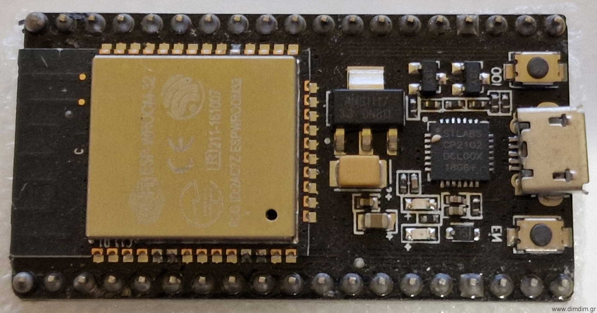
These things are dirt cheap, costing something like 4-5€ with shipping and feature a 32 bit dual core processor, plenty of flash and RAM and a wireless module supporting both WiFi and Bluetooth. They also sport a lot of GPIO and there is official Arduino support from the manufacturer ( https://github.com/espressif/arduino-esp32 ), so programming them is very easy. In fact, here is a guide to flashing the module with the Arduino IDE.

So the module arrived a couple of months later, in typical China-to-Greece-by-post fashion. By that time I had literally forgotten what I had bought it for. So it then lay there in a drawer for 4 or 5 years until I randomly came across an article that mentioned that it can output I2S! That was news to me, and obviously interesting.

After a brief google search I came across this project: https://how2electronics.com/simple-esp32-internet-web-radio-with-oled-display/ which then led me to this very cute library: https://github.com/schreibfaul1/ESP32-audioI2S

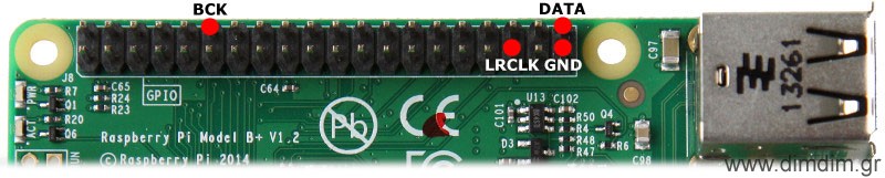
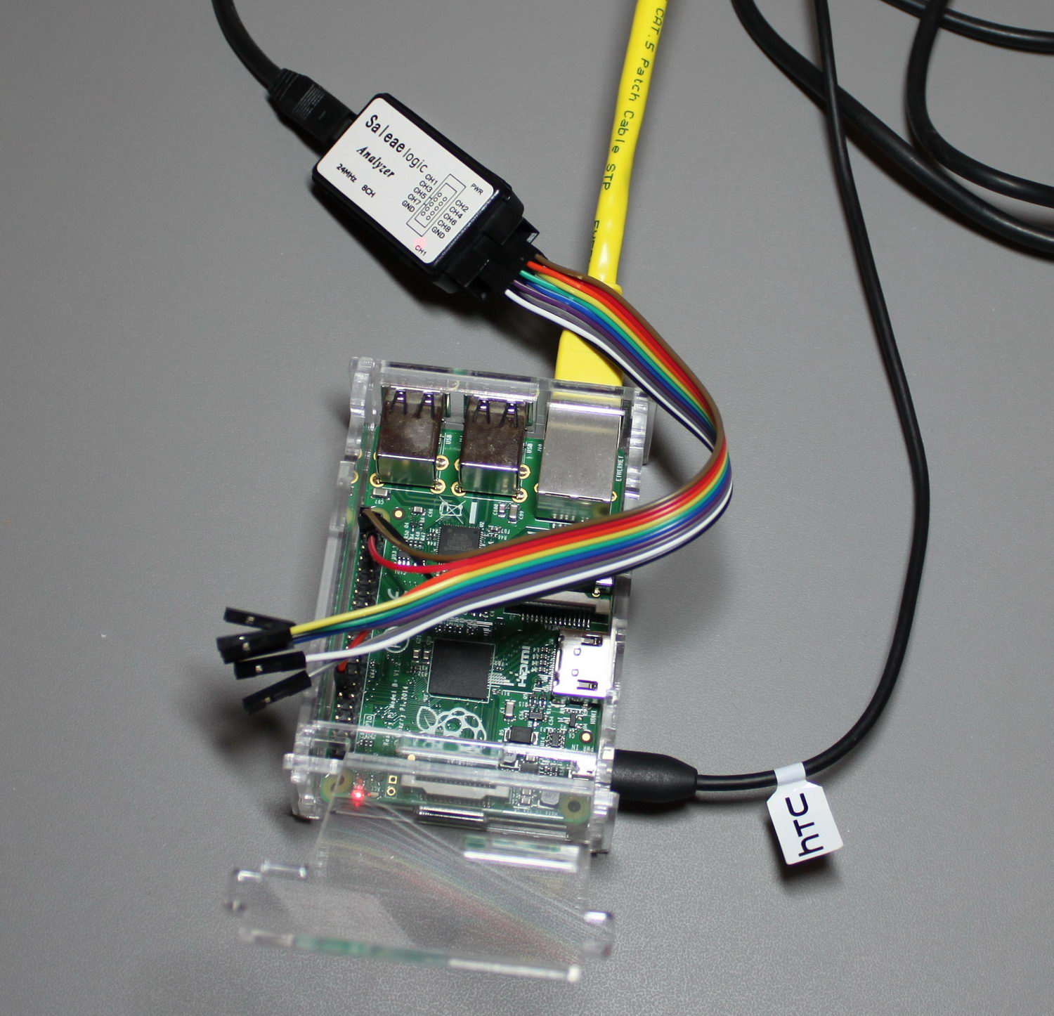
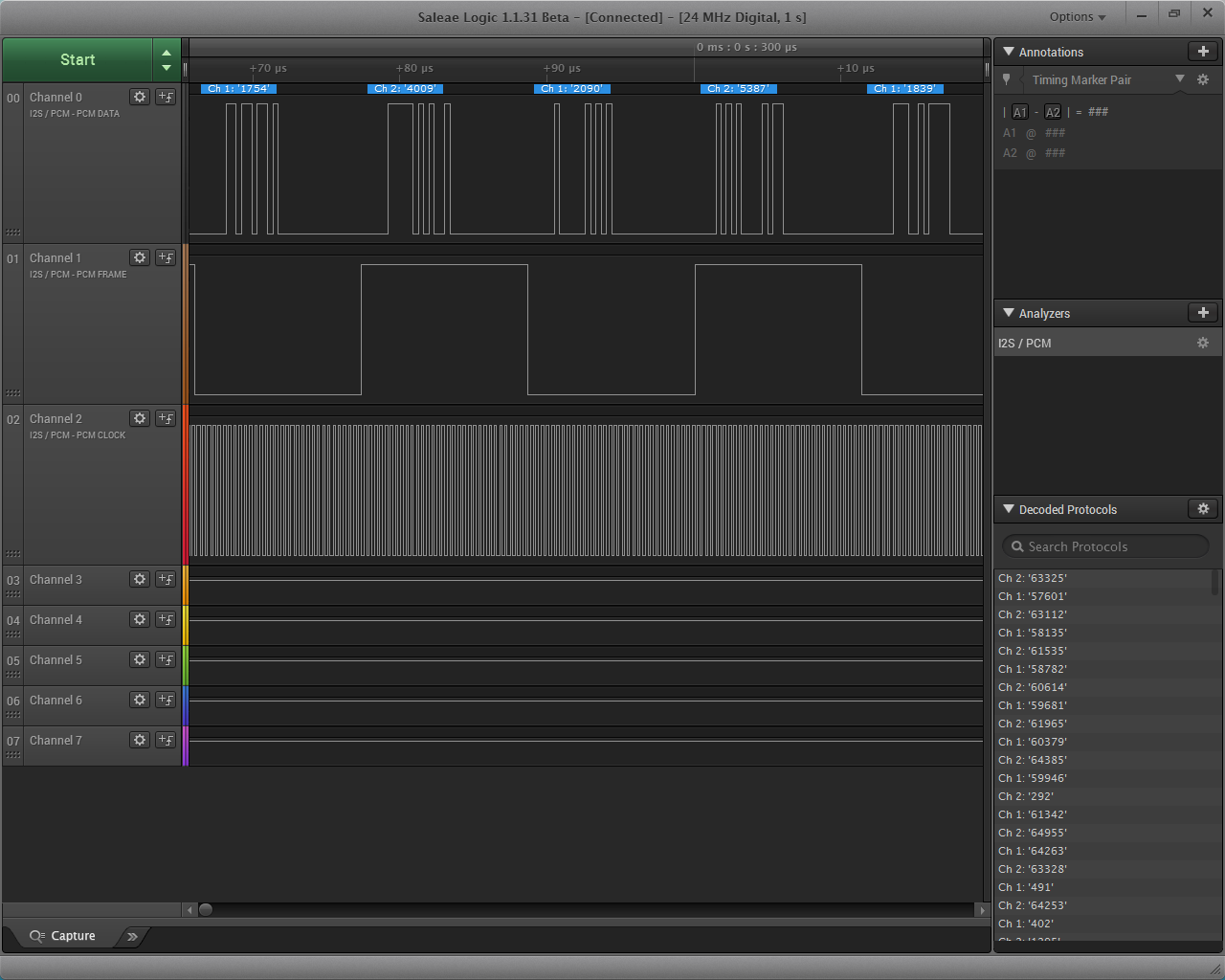
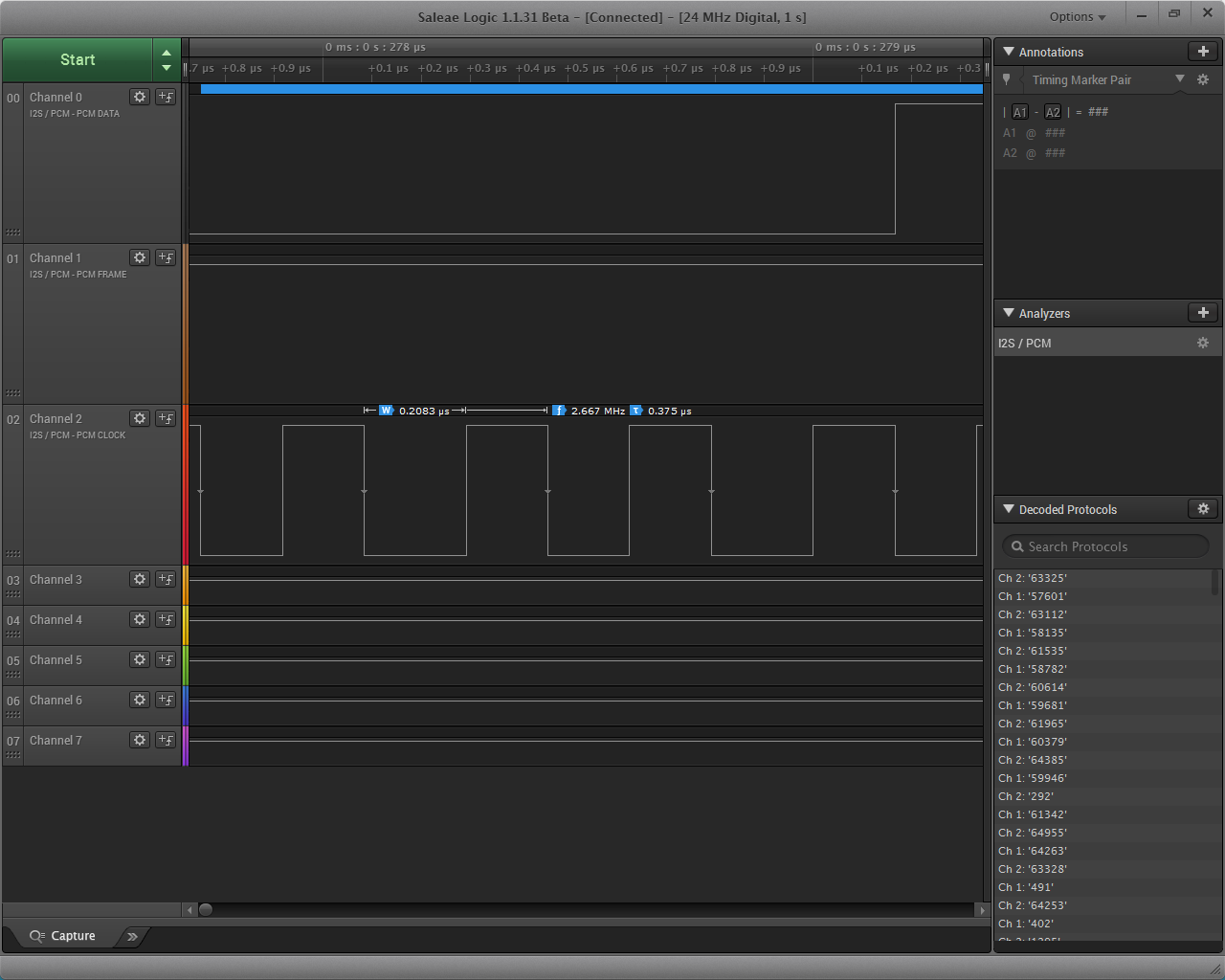
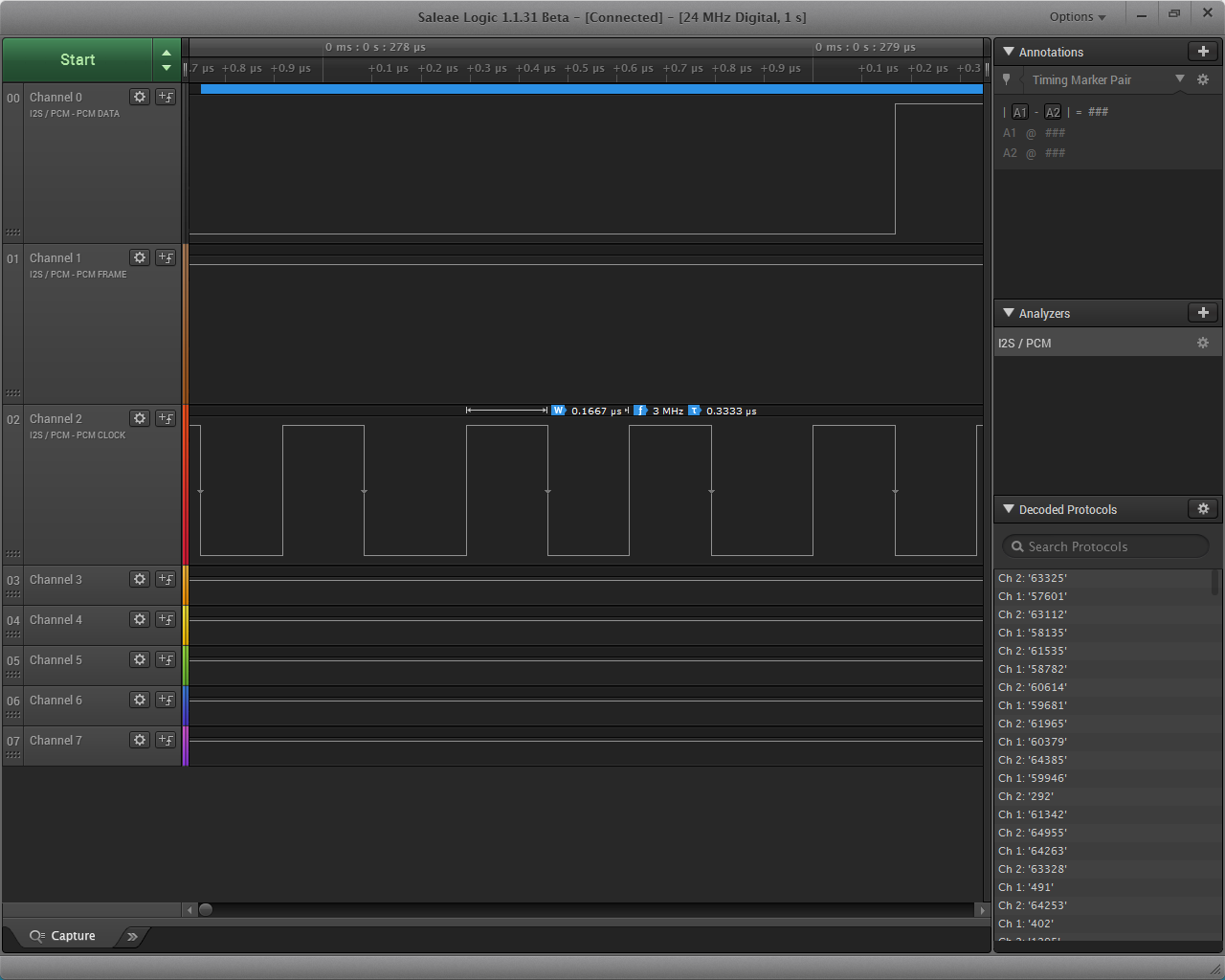
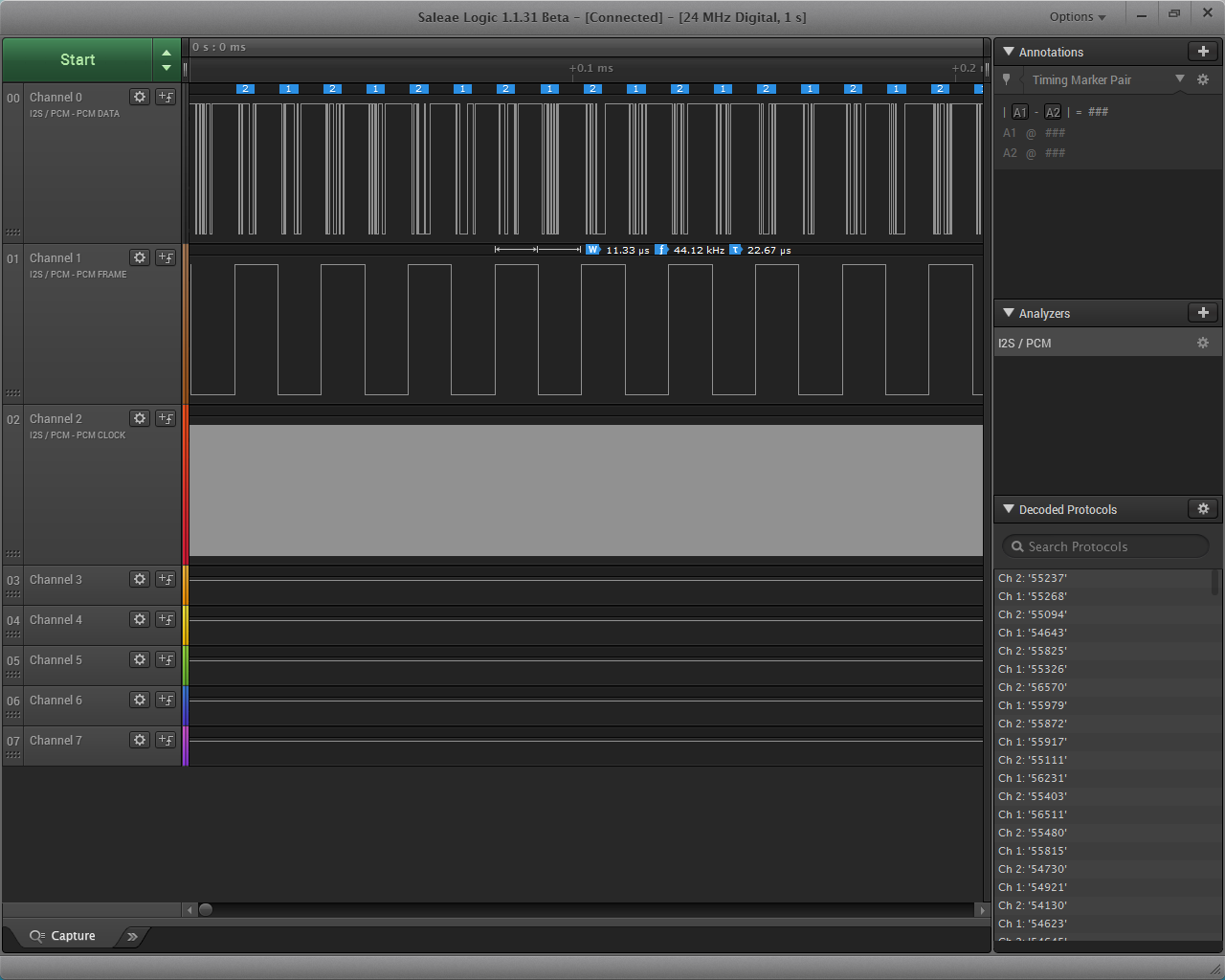
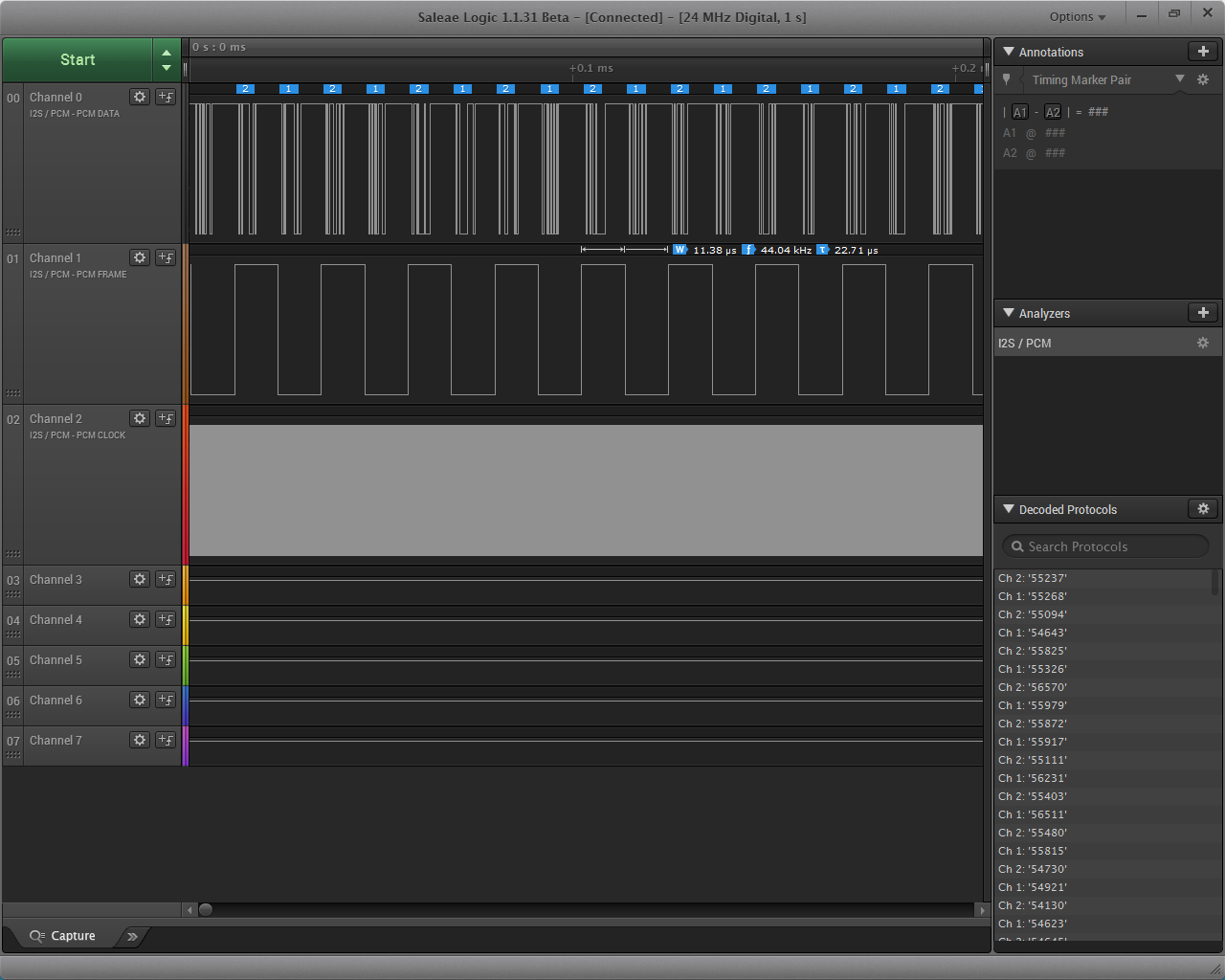
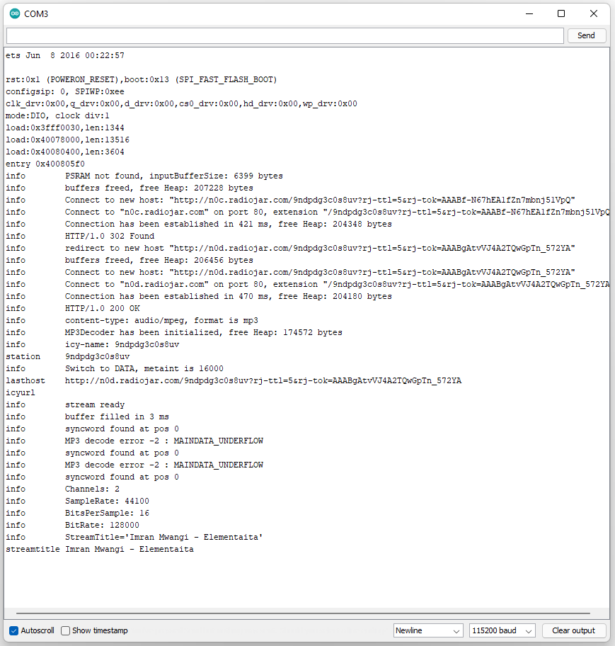
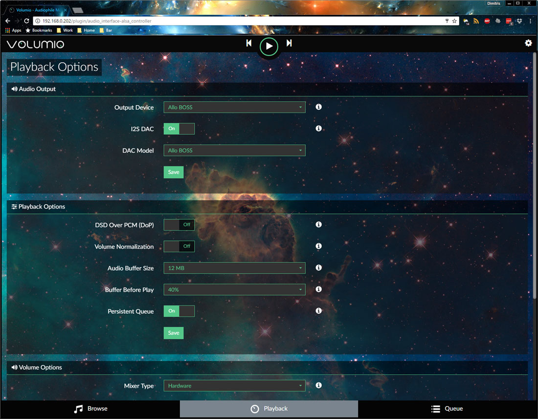
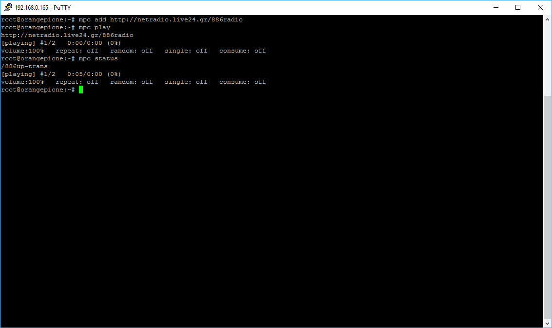
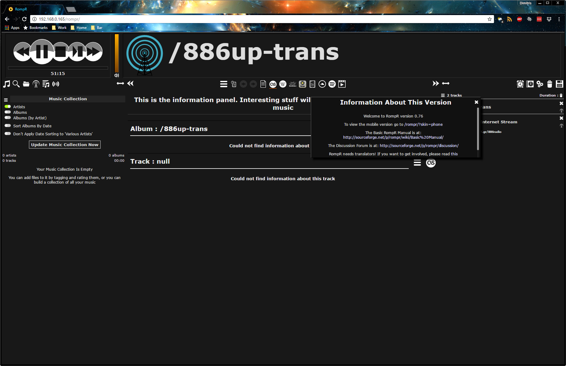
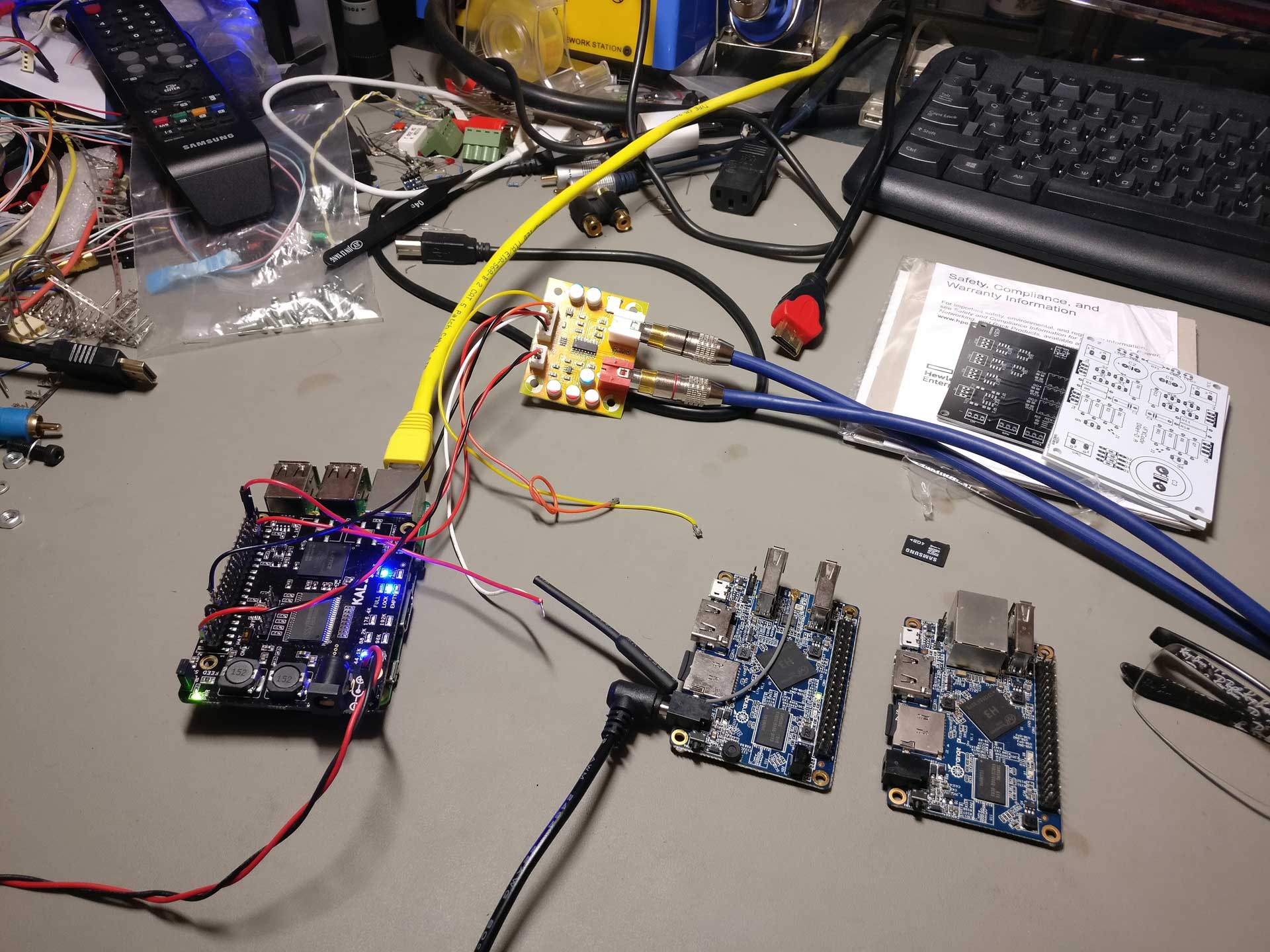
So I entered my favorite internet radio’s URL, plus my WiFi credentials into the code and loaded it to my ESP32 using the Arduino IDE. Surely enough, I saw in my serial port that the ESP32 connected to my WiFi access point and then opened successfully the streaming radio station. I could see on my oscilloscope that it was indeed outputting I2S. Excellent!

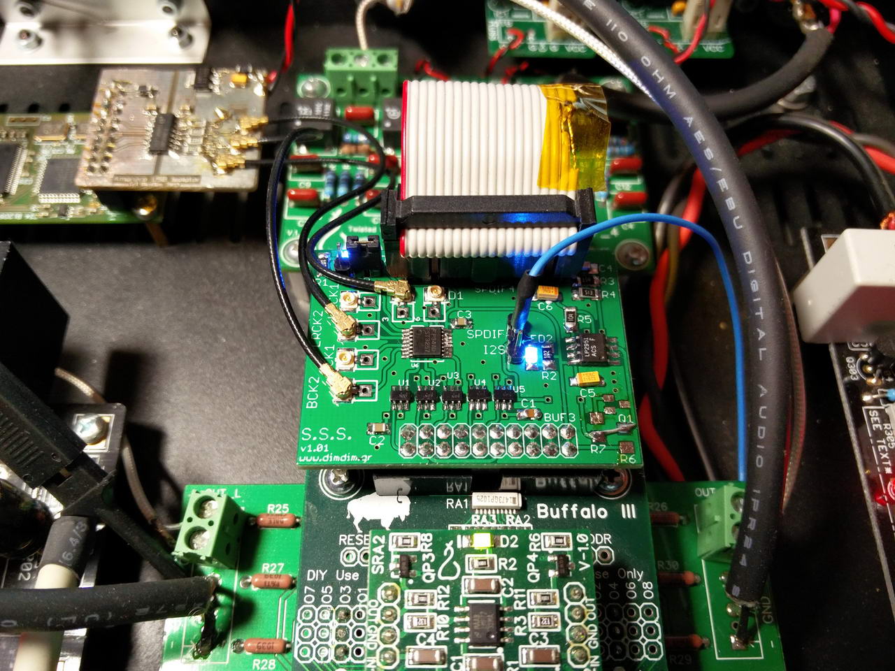
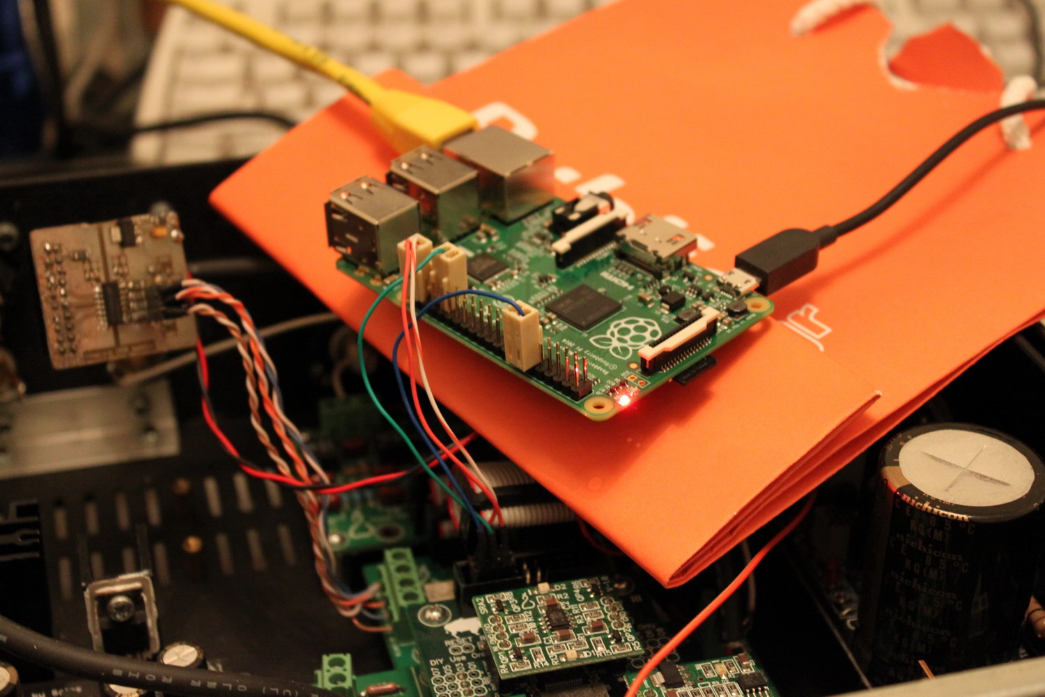
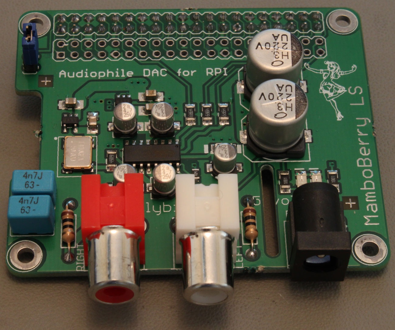
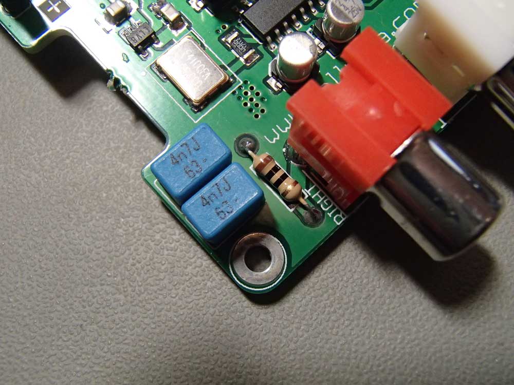
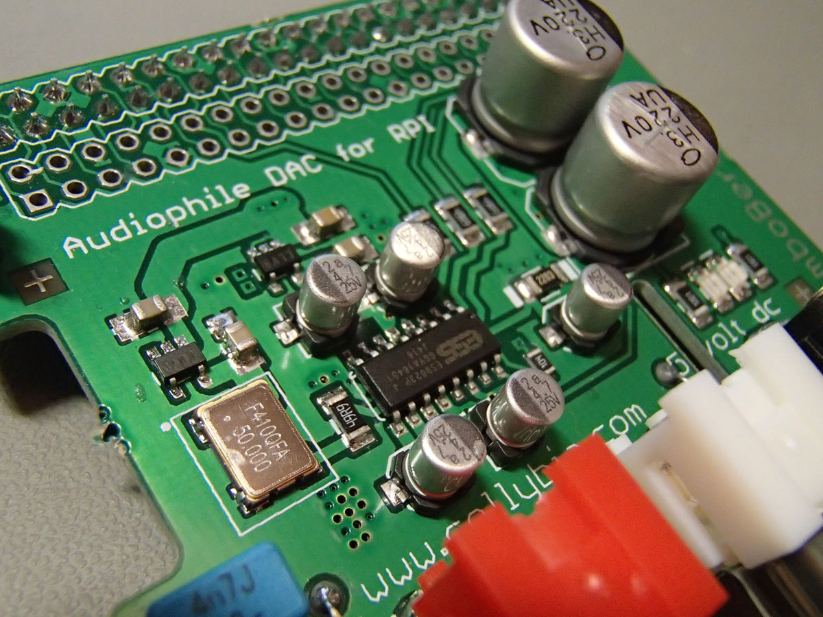
Then I hooked up a tiny DAC board that I had lying around (sporting an ES9023 chip – very practical since the ESP32 does not output an MCLK signal), and the thing worked flawlessly on the first try!

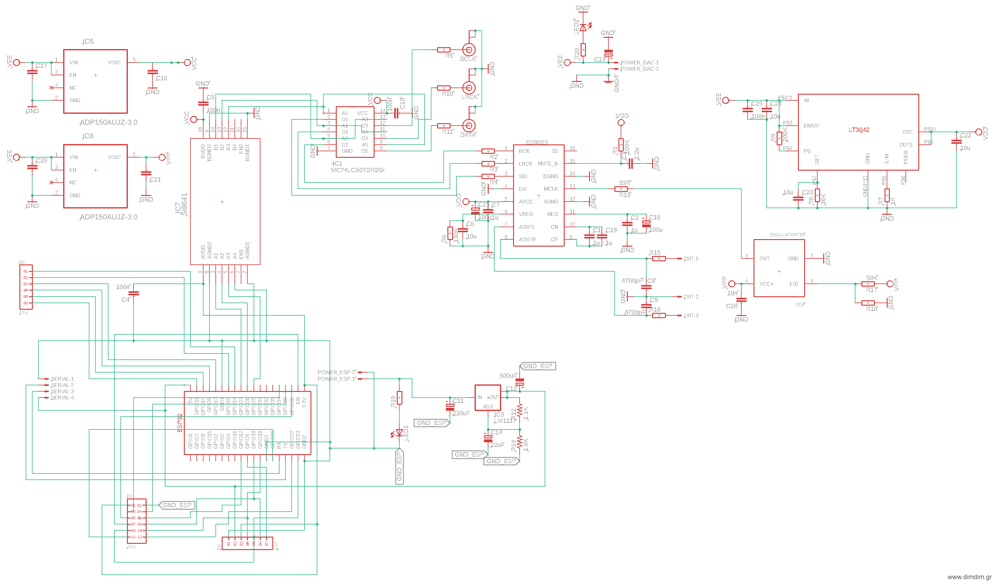
So I thought that I should do a carrier board for the ESP32 that would perform the following:

  1. Host the ESP32 board,
  2. Provide regulated power to the ESP32,
  3. Provide headers for serial port (programming), SD card, extra I/O, and perhaps for an LCD,
  4. Do galvanic isolation of the I2S signals,
  5. Provide buffered I2S output for connecting to an outboard DAC board,
  6. Have an on-board DAC with line level outputs.

Since this device would only stream internet radio (a.k.a. “heavily compressed audio”), the on-board DAC did not have to be anything special. So let’s go with the all time classic ES9023.

Let’s also do a relatively good power supply for the critical component (dac chip) but nothing extreme. The rest of the audio-related components can be powered by well respected LP5907 LDOs, while the actual ESP32 can be powered by a run-of-the-mill LM1117.

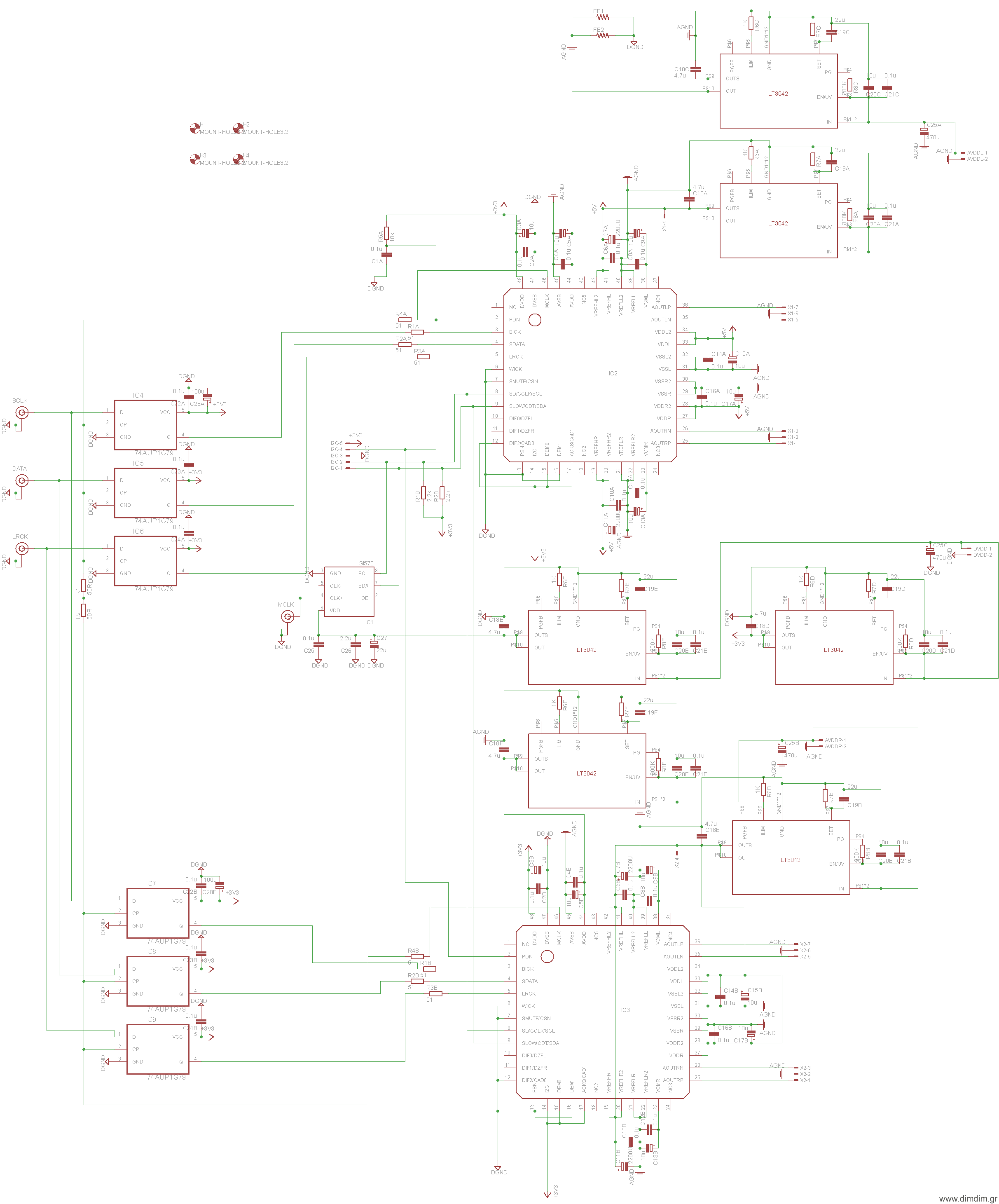
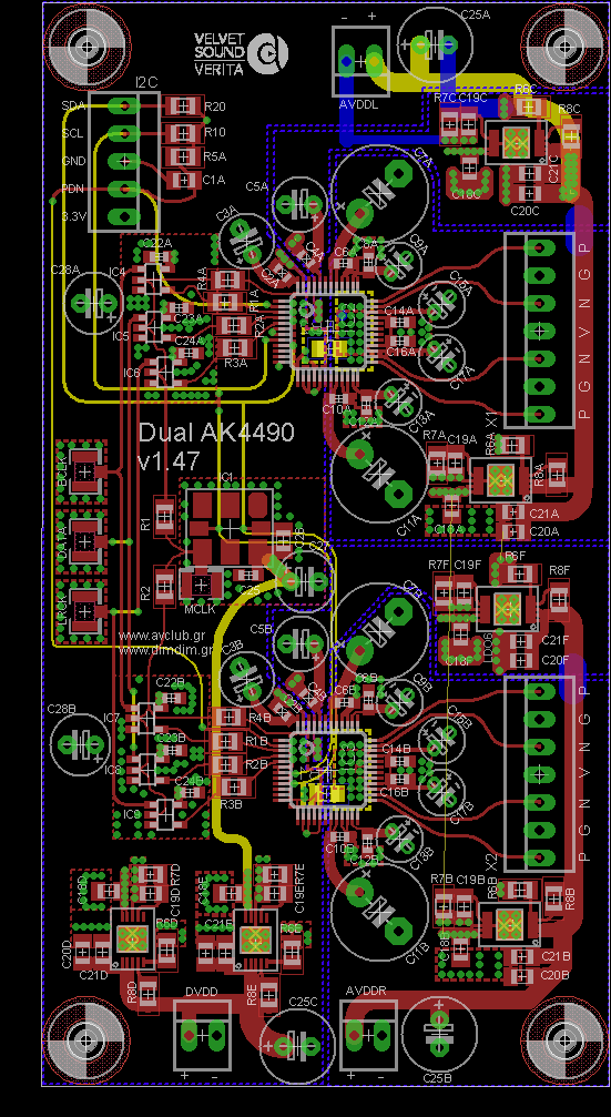
So this is what I came up with:

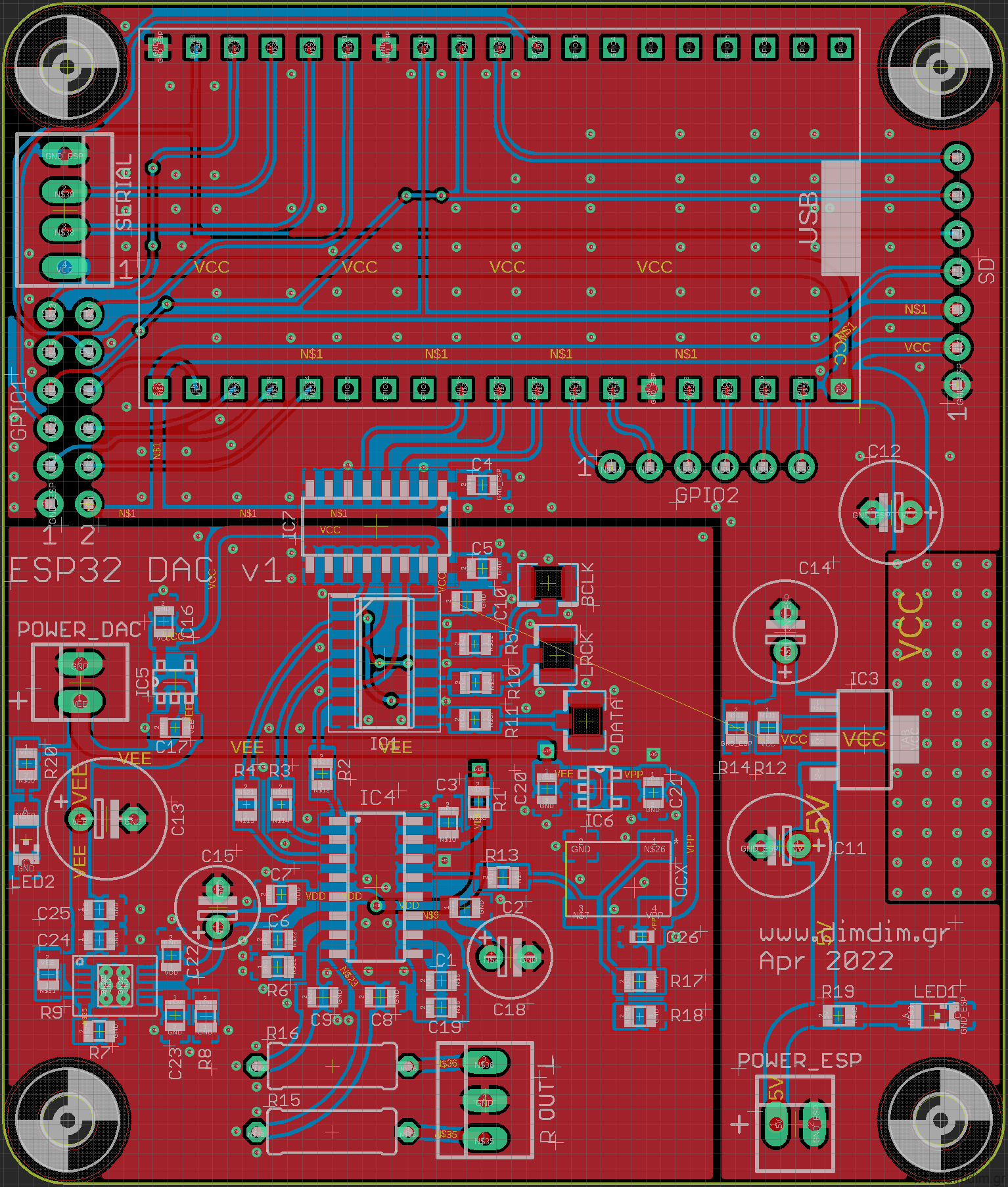
Gerbers were generated ( ESP32_DAC_v1_Gerbers (593 downloads ) ) and an order was put into a well known Chinese board manufacturer.

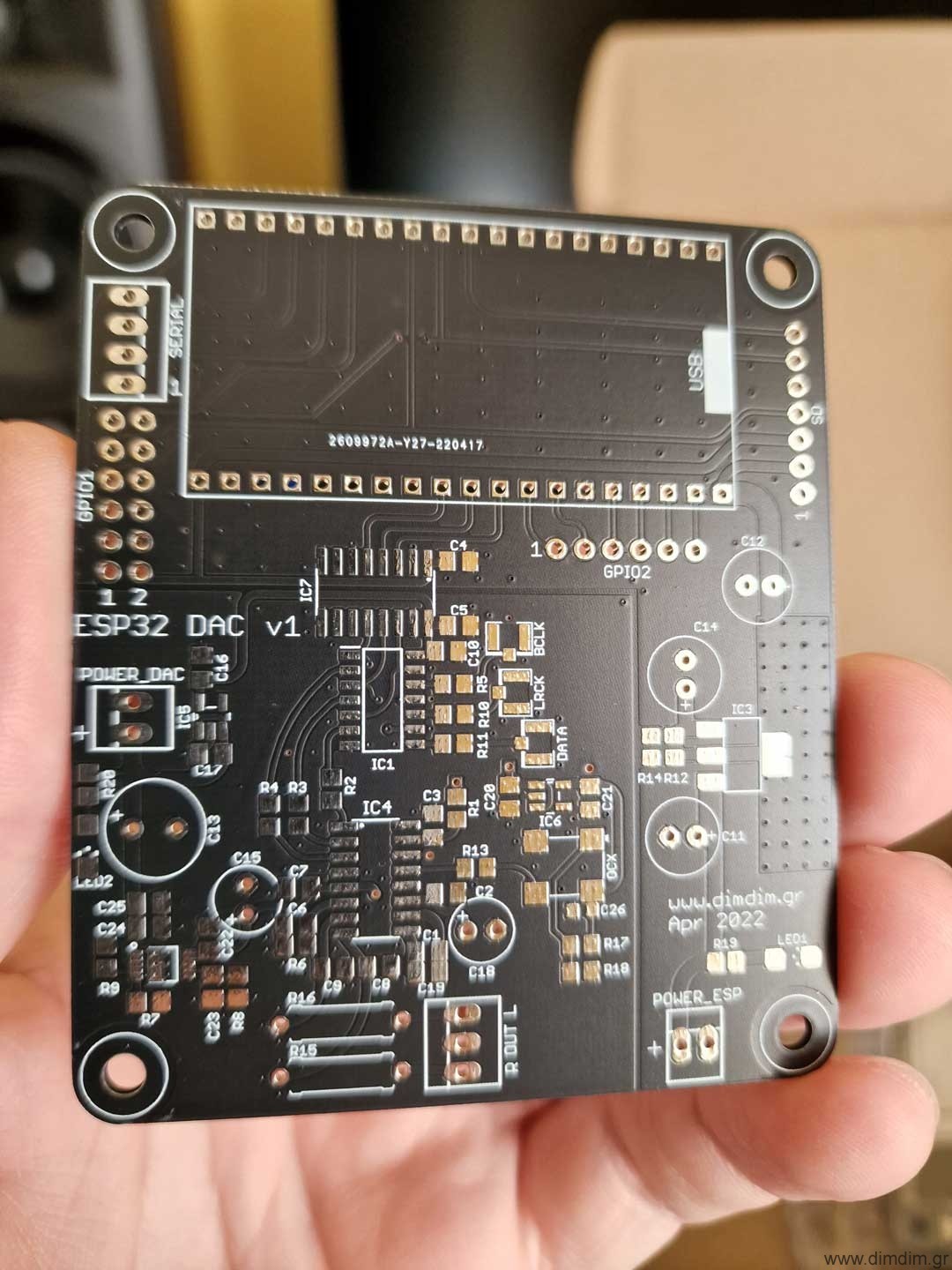
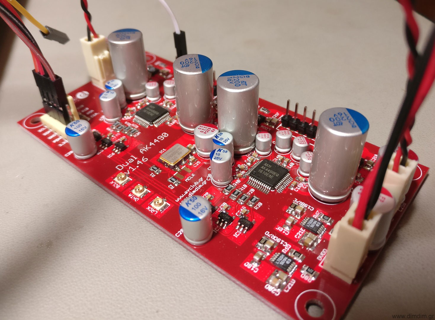
A couple of weeks later the boards turned up:

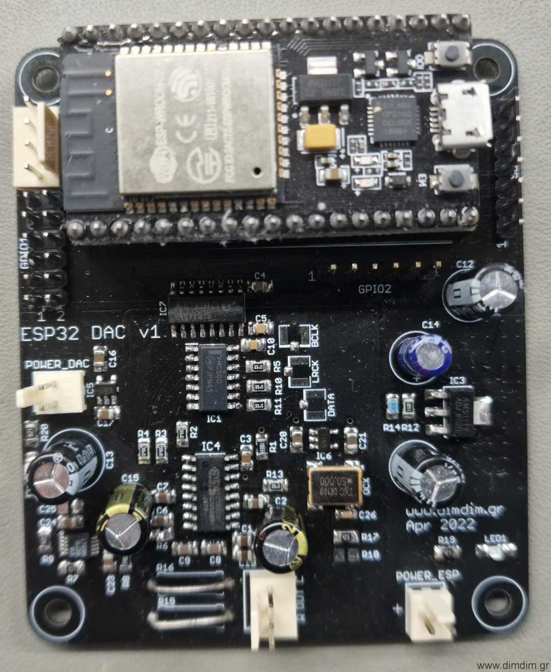
And were promptly populated:

Here is the complete Bill of Materials for this board: ESP32_DAC_v1_BoM (911 downloads )

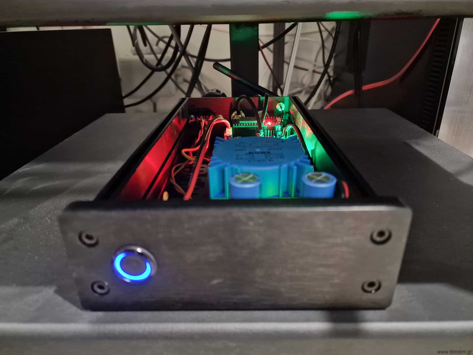
A suitable power supply was also implemented and integrated into a proper case:

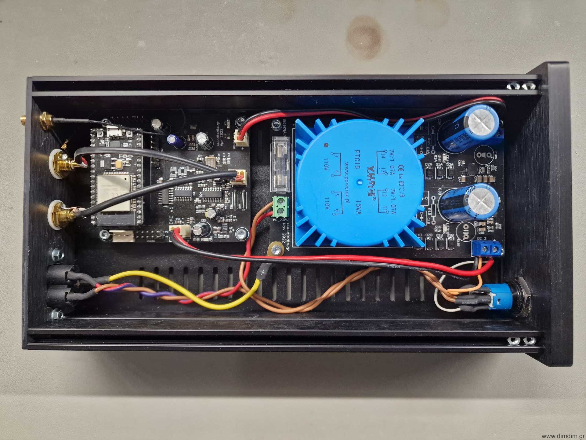
And here is the completed device in action:

This was a pretty simple and relatively low cost project, an ideal way to keep busy for a couple of winter evenings.

Also it is a good way to listen to high fidelity internet radio without needing to keep an entire PC and DAC powered up. So it’s good for the environment.

It would not be difficult to add an LCD that would display the artist and track that is playing.. perhaps sometime in the future.

Arduino controlled Dual Mono AK4490 DAC (Part 1)

For the better part of a year I’ve been busy developing what one would call a “respectable” DAC from scratch. It has been a team effort, with different people becoming more involved with specific aspects of the project, but pretty much everyone involved ended up learning a lot about DACs. Right now, the project is for the most part finished, in that it is fully functional with a USB input and a pair of single ended outputs (or balanced, if you use a passive transformer-based stage). It is controlled by an Arduino-compatible micro-controller, running my aKduino v2 code (more on that in a future post).

I will do a series of posts detailing the design and build process, with each post covering a specific PCB. When the series is complete, the contents of all of the posts will be concatenated into a project page.

So, without further ado, this is the schematic of the main DAC board:

(Right click, Save Image As.. to download it in full resolution)

This is the 4-layer PCB:

This is the parts placement diagram:

And this is the BoM (v1.9) in xls format: Dual AK4490 DAC (main board BoM) (9950 downloads )

Design considerations

The design goal was to do a dual mono design so as to maximize SNR and channel separation. A 4-layer PCB design was chosen so as to have a very solid, low impedance ground plane as well as proper power and signal planes. The I2S, audio signals and power after the local LDO regulators are routed on the top layer, the 2 middle layers are ground and power planes, and the bottom layer serves to route I2C signals and some power lines.

Power

All of the local power supplies are implemented using the currently top-of-the-line LT3042 LDOs. The VDDL & VDDR (analog power supplies) are set to 7.2V so as to maximize SNR and dynamic range. There is provision for providing separate pre-reg power supplies for the L and R channels (headers AVDDL and AVDDR) but I don’t consider that to be critical to SQ since there are local LDOs and the power draw is very very small. In my implementation I’m using a common pre-reg for both the AVDDL & AVDDR. The AVDDs and DVDDs are also supplied by LT3042 LDOs set to output 3.3V. The Si570 has its own dedicated 3.3V supply implemented with an LT3042 and features extra filtering.

Overall, the power requirements of the board are:
1) AVDDL: 8-10V DC at 40mA max
2) AVDDR: 8-10V DC at 40mA max
3) DVDD: 4-6V DC at 200mA max

Clocking & input signals

It was decided that the MCLK would be provided by a programmable low jitter oscillator, namely the Si570. This way we could select different MCLK frequencies at will, supporting different sampling rate families and different USB to I2S boards.

Speaking of USB to I2S boards, the DAC board has a very specific requirement: The USB board must be able to receive MCLK externally. In other words, the DAC board and USB board must be clocked from the same oscillator. This is due to the AK4490’s design. Unlike the ESS designs which by default run asynchronously, it needs to be on the same clock domain as its I2S sources.

So, the DAC board needs to output MCLK back to the USB board. There exist a number of USB boards that support that. The most popular ones are the Amanero Combo384 and JLsounds’ I2SoverUSB.

Since I had decided to do reclocking using flip-flops as close to the AK4490s as possible, and the flip-flops are clocked by the MCLK, its frequency needs to be sufficiently high in order to reclock signals corresponding to high sample rates. This translates to 49.152 MHz for sampling rates of 384KHz. If you’re content with going only up to 192KHz, you can use a MCLK of “just” 24.576 MHz. Of course you will also need the corresponding MCLKs of 45.1584 and 22.5792 MHz for the 44.1K families of SRs.

If you decide that you don’t want to do reclocking on the DAC board, you can just not solder on the flip-flops and just connect the proper pads together with some wire so as to bypass them. That way you can run with 22.5792 & 24.576 MHz clocks with SRs up to 384KHz (and probably beyond..).

If you decide that you would also prefer to not use the Si570 and just clock the DAC board directly from your USB to I2S board (or other suitable I2S source) you can also do that. You just don’t solder-on the Si570 and make a couple of changes to the Arduino code (to be implemented..).

But I urge you to try the Si570 & reclocking way first..

Construction hints

Start by first soldering on the power supply components (LDOs, resistors, caps, etc.) and testing that everything works the way that it should.

The LT3042s are pretty tiny and its easy to make a mistake while soldering them. I’ve found that the easiest method is by using a hot air rework station. First I use a regular soldering iron to tin the thermal pad and the pads with a small amount of solder. Then I apply a good amount of high quality solder paste, put the LDO on top of the pads and heat the area of the board until the solder melts. I set my hot air station to a relatively low temp of ~280 degrees C and the process takes less than a minute (per LDO). But you could also solder them with a soldering iron. To solder the heatpad, warm up the pad from the underside of the board and add solder.

After the power section, you should solder on the AK4490s and other low profile components. I do that with a low power (18W) soldering iron with a fine tip.

Next up is the Si570 programmable oscillator. I start by putting a little solder on one of the pads:

Then I add soldering paste and I place the Si570 on top of the pads. I use the fine tipped soldering iron to melt the solder on the tinned pad, effectively soldering the Si570 on the board. I then proceed to solder the rest of the pads by applying heat with the soldering iron to the side of the pads of the Si570 and adding solder.

You should finish up by soldering the electrolytic capacitors and other higher profile parts.
Beware that the spacing around the electrolytics is very tight. You should take that into account when selecting parts. The parts in the BoM are sure to fit in the available space.

That’s it for Part 1. Stay tuned for Part 2: The Controller.

Mamboberry LS DAC+ vs. Boss DAC vs. Piano 2.1 Hi-Fi DAC with and without Kali FIFO Reclocker


Back in September Allo.com had sent me their Piano 2.1 DAC along with their Kali reclocker, but I didn’t have any other DAC HATs to compare it to and it wouldn’t be fair to it to compare it to my Soekris or my Buffalo III DACs. This changed this week, when they sent me their new Boss DAC and by happy coincidence I also had the chance to spend a few days with the Mamboberry LS DAC+.

It was showdown time.

Technology

But before I get to the interesting stuff, a few words about the technology used in RPi DAC HATs.

An RPi DAC HAT is fed audio using what is called an I2S protocol. I2S was designed for transferring audio between ICs located on the same PCB, but audiophiles have somewhat stretched its capabilities by using it to transfer audio data between PCBs and some times even between stereo components. It is considered the best, most accurate way to transfer audio data, provided that the I2S signals are properly generated. The RPi has a well-known and documented problem generating proper I2S signals. The problem has remained the same, even though the RPi is now at its 4th generation.

Right now, there exist two ways to deal with this problem:

1) Use some kind of FIFO buffer and reclocker in order to regenerate the I2S signals. Examples of such FIFO reclockers are Ian’s FIFO and allo.com’s Kali. The RPi is configured to output a standard I2S signal and then it’s the job of the FIFO buffer to “fix-up” this signal. The resulting I2S signal is of very high quality, since the FIFO buffers utilize very high quality oscillators and power supplies.

2) Run the DAC in what is called Master Mode. Let’s talk a little more about that.

There are two modes of operation for I2S compatible chips. In case of DAC chips:

Slave mode: The DAC receives all of the I2S signals (BCLK, LRCK and DATA) from the RPi. It is susceptible to jitter since the RPi’s I2S output is problematic.

Master mode: The DAC uses its on-board oscillators to generate the BCLK and LRCK signals, it then sends these signals back to the RPi which uses them to clock its DATA output. This way the RPi does not need to use its own clock, which is problematic for audio use. The end result is an I2S signal of reasonable quality.

Note that not all DAC chips can operate in either of the two modes. Most widespread is the Slave mode, in fact practically all DAC chips support it. The Master mode is supported by a small percentage of DAC chips, like the PCM5xxx series by Texas Instruments or the new ESS DACs (like the ES9038Pro). Well known DAC chips that do not support Master mode include the older ESS chips (ES9018, ES9018K2M, ES9023, etc) and the Asahi Kasei DACs (AK4490, AK4495, AK4497, etc.).

The DACs

With that out of the way, lets see our contestants.

The Mamboberry LS DAC+ is a moderately priced (54.90€) ES9023 based DAC designed to run in slave mode to the RPi. It is considered one of the better sounding HAT DACs out there.

It has an on-board high quality oscillator (by Fox) running at 50MHz (this essentially means that the 9023 is running at asynchronous mode, that is it is resampling all incoming PCM signals), very good quality LDO regulators and passive components.

It may be powered either through the RPi or by an external (preferably linear) power supply. Officially the ES9023 supports sampling rates up to 192KHz but unofficially it goes up to 384KHz / 32bit. It doesn’t really require special software support on the RPi, you just set it for “generic I2S output”.

The Allo.com BOSS DAC is a somewhat pricier (~70€) master mode DAC.

It is based on the PCM5122 DAC, powered by a top-quality LT3042 LDO regulator utilizing DC filtering by very high quality capacitors (including a 330.000uF supercapacitor!).

Clocking is done by a pair of NDK extremely low jitter and low phase noise oscillators (45.1584 & 49.1520 MHz), powered by their dedicated LDO regulator. Their output is buffered by an NB3L553 clock fanout buffer IC which further reduces the jitter.

Sampling rates up to 384KHz / 32bits are officially supported. It’s powered through the RPi, but it has an “Optional 5V battery power in connector” for future use. I suspect that this connector can also be used to power the Boss, but a certain resistor will need to be removed to isolate this power from the RPi. This DAC needs a special driver, since it needs to set the RPi in slave mode and also communicate with it via I2C to set operating parameters and utilize the PCM5122’s hardware volume control. When the DAC is receiving data from the RPi, the indicator “LED1” lights up.

The Allo.com Piano 2.1 Hi-Fi DAC is another moderately priced (~55€) slave mode DAC, based on PCM5142 DACs. Notice the plural.

On board this HAT we have two DAC chips that output a total of 4 channels. Each of the DAC chips also contains a DSP core, capable of doing equalization, filtering or other functions. These DSPs can be configured using TI’s PurePath software, but that is not a trivial task. The distributions that include built-in support for the Piano 2.1 come with a pre-built set of filters, capable of essentially configuring the DAC in 2.1 mode so that it can be used with one or two subwoofers. The analog sections of the DAC chips are powered by two top-quality LT3042 LDO regulators.

There exists no on-board oscillator, since the DACs are running in slave mode. Sampling rates up to 384KHz / 32bits are officially supported. Power is supplied by the RPi. As you can imagine, this DAC also needs a special driver, since it needs to set up the filters in each of the DAC chips plus to utilize the PCM5142s’ hardware volume controls.

A word about audio distributions

There are many audio-oriented distributions available, such as Archphile, RoonAudio, Moode and Volumio. In order to do a fair comparison, I opted to use the same distribution for all tests. The logical choice was Volumio, since it includes proper support for all of our DAC HATs.

Volumio is very easy to install and is very responsive in my RPi3. No complaints whatsoever.

Testing Methodology

The idea was to test the DACs in their default operating mode, that is with no mods and no exotic power supplies. When testing without Kali, the RPi3 & DAC were powered by a 5V 2A SMPS I had lying around from an old tablet. It’s a pretty high quality unit, made by HP. Still, at the end of the day it’s just a wall-wart SMPS.
When testing with Kali, I powered the RPi3 with the same SMPS plus I used an 7805-based linear power supply for the Kali & DAC (jumper on Kali was removed to isolate its power from the RPi’s). Again, nothing exotic. Just a relatively low power (1A max) linear power supply.

After I had an initial listen to all of the DACs in pretty much every possible combination, like “plain DAC” or “DAC with Kali” (where applicable of course) and drawn my conclusions, I thought I would take the system “on tour” to a couple of my friends and their superior sound systems. By doing this I was getting a second and third opinion. So, friend#1’s system is a full-blown MBL installation costing upwards of six figures. His main DAC & transport’s cost is in the 20K range. Friend#2’s system is a more DIY affair, consisting of big (and I mean BIG) Magnepan speakers, diy solid state power amp (several hundred watts per channel, many of them in class A, it makes a lot more than a ding in his power bill), diy preamp, Sony XA50ES modified CD player plus (on loan from me) a Soekris DAM1021 DAC.

At friend#1’s, we used an SPL meter to equalize the volume levels between all of the DACs. We listened to 3 specific tracks. At friend#2’s, we also listened to the same 2 or 3 tracks on all of the DAC combinations but didn’t take much care of level matching. The observations of my two friends were practically the same, so I won’t distinguish between them.

The Results

We started with just the RPi with Mamboberry LS. The sound was OK, not nearly what you would call “hi-end”, but considering the DAC’s cost it was more than satisfactory.
We then moved on to the RPi with the Boss. The improvement in audio quality was more than apparent. The soundstage became better defined, the instruments more clear, the bass just.. more, but in a good way.
Next up was the Mamboberry aided by Kali. Kali did more than just fix up the I2S signal – it also provided clean power to the Mamboberry. Now the Mamboberry began to show its teeth. This combination gave a more clear result than the Boss DAC, like the music became even more life-like. The bass did not have the same authority, but overall the combination Mamboberry & Kali definitely sounded superior to the Boss.
Finally, we teamed the Piano 2.1 to the Kali. The Piano was configured in stereo mode, since there were no subwoofers present. This combination gave the best overall result, giving a more “analog”, musical result. Its sound was the most smooth of all of the combinations, while at the same time it was the most life-like. You could say that it was the least fatiguing of the bunch.

After we were done comparing the HAT DACs, we thought we should listen to our “proper” DACs, just to put things into perspective. To no surprise, both my friend#1’s DAC and my Soekris properly cleaned the floor with the HAT DACs and it’s a good thing that they did – otherwise we would have felt pretty dumb having wasted so much money on so-called “proper” DACs while we could have got the same result with these DAC HATs. Phew.

So, the end result is not really surprising. The more money you spend, the better sound you will get. No giant killers here. But regarding value-for-money, I think that the Boss DAC claims the prize.

Happy π day everyone! 😀

Orange Pi One & Lite as music streamers (Part 2)

In Part 1 we installed Armbian on our Orange Pi One (or Lite) and set it up on our local network. At this point, all our work can be done on any PC that is on our network, via SSH connection (putty etc.).

Enabling I2S output
First order of business is enabling the Pi’s I2S output. To do that, we need to edit what is called a FEX file. This FEX file (script.fex) is essentially a hardware configuration file for the Pi. For example, if we wanted to enable or disable a serial port at the hardware level, we would edit this FEX file.

The problem is, this FEX file exists in binary form in our file system so in order to edit it, we need to convert it to a text file. To do that we use the bin2fex command.
So, step by step:

Log into Pi as root and type:

cd ..
cd boot
bin2fex script.bin script.fex
nano script.fex

Nano is a relatively user friendly editor for Linux, I use it for all my text editing.

Look for twi1. Change it to this:

Then look for pcm0. Change it to this:

Once we are done editing the file, we hit Ctrl-X and choose to save the file before exiting.

Then we need to convert the .fex file back to .bin. We type:

fex2bin script.fex script.bin

and we reboot.

We confirm that we have a new sound device called snddaudio by typing in aplay –l :

Network Share configuration
Now that our I2S output is enabled, we need to give our Pi access to our music. I prefer to store my music in a Synology NAS so I need to configure a network mount on the Pi.

We start by creating a mount point for our share. That can be any empty folder. I choose to mount my shares in mnt/nas-samba. Let’s create that:

cd /mnt
mkdir nas-samba

Then we install the package cifs-utils:

apt-get install cifs-utils

Now we get to the actual mounting of the share:

nano /etc/fstab

For my setup, I add this line: //192.168.0.32/Music /mnt/nas-samba cifs username=,password=,ro,iocharset=utf8,nolock,noauto,x-systemd.automount,x-systemd.device-timeout=10,sec=ntlm,rsize=8048,wsize=8096

This tells our Pi to mount the share //192.168.0.32/Music to the folder that we created above using the credentials that I have supplied. You will need to customize this command to your own network environment.

After a reboot we go to our mount point and have a look inside:

To confirm that the share has been mounted we can use the df -h command, as can be seen above.

MPD Installation

The software on our Pi that does the actual music playback is called MPD (Music Player Daemon). To install it we enter:

apt-get install mpd

This will take a while, since MPD has a bunch of dependencies that will also be downloaded and installed.

Once the installation is finished, we will need to configure it. To do that, we edit mpd.conf:

nano /etc/mpd.conf

We need to do three things:

1) Set our music directory to /mnt/nas-samba:

2) Change network binding to “any”:

3) Change the “audio” setting to select our I2S audio output:

We put in this:

audio_output {
        type            "alsa"
        name            "I2S DAC"
        device          "hw:1,0"
        format          "*:32:*"
        mixer_type      "software"
#       mixer_device    "default"       # optional
#       mixer_control   "PCM"           # optional
#       mixer_index     "0"             # optional
}

This configuration creates an ALSA device called “I2S DAC” that utilizes the Pi’s I2S output. It up-samples all files to 32bits (don’t worry, it doesn’t deteriorate the SQ in any way. It just pads with zeroes when necessary) in order to make this setup compatible with my Buffalo III. Also, it enables software volume control. You can disable it by commenting out the relevant line.

Once we are done, we save the file and quit nano. We then restart MPD to apply the changes:

systemctl restart mpd

MPD Clients Installation

Once MPD is installed, we will need a “human friendly” way of interfacing with it.
In other words, we will need to install what is called a “client”. There exist all kinds of clients, from command line based ones, to web-based environments, to apps for smartphones and tablets. In my setup I install two clients, a command-line based one (mainly for testing purposes) and a web-based one for more general use.

To install the classic command line client “mpc” we enter:

apt-get install mpc

That should take almost no time.

Now that we have at least a basic client installed, is a good time to check that MPD is actually working. To do that, I usually do this:

mpc add http://netradio.live24.gr/886radio
mpc play
mpc status

What these commands do is:

1) Add my favorite internet radio station to MPD’s playlist
2) Start playback
3) Check that playback has indeed started.

If it all went well, you should see something like this:

If you have already connected an I2S DAC, you should be hearing music. This means that your MPD is functioning, so the hard part is done.

If by chance you’re looking for the Orange Pi One / Lite’s I2S pinout, you’re in luck. Here it is:

At this point you have a choice to make. You can either install an app on your smartphone or tablet and get things done that way, or you can install a web-based “rich” client. I like rich clients, so after a brief internet search I came across RompR.

Installing RompR

The people behind RompR have written a pretty comprehensive installation guide. All of the necessary info is there, for all platforms. But, since this post has to do specifically with the Orange Pi, I’ll give you a customized version of the installation guide. This should take you about 10 minutes. Let’s start.

First we’ll download and install all of the necessary packages:

apt-get install apache2 php5-curl php5-sqlite imagemagick libapache2-mod-php5 php5-json

Then we will download the actual binary into a temp folder:

cd /mnt
wget http://downloads.sourceforge.net/project/rompr/rompr-0.78.zip

Next step is extracting the files to /usr/bin/rompr:

unzip rompr-0.78.zip -d /usr/bin/

..and we get to the editing of .conf files part:

nano /usr/bin/rompr/apache_conf.d/Apache2.4/rompr.conf

We have to replace every /PATH-TO-ROMPR with /usr/bin/rompr:

When we’re done we exit nano, saving the file.

Then we copy this file to its final location:

cp /usr/bin/rompr/apache_conf.d/Apache2.4/rompr.conf /etc/apache2/conf-available/

We take care of a few permissions:

chmod -R ugo+rw /usr/bin/rompr/prefs
chmod -R ugo+rw /usr/bin/rompr/albumart

And we finish up:

a2enconf rompr
a2enmod expires
a2enmod headers
service apache2 restart

At last, it’s time to see if our installation works. We type into our browser our Pi’s IP followed by /rompr:

All we have to do now is update MPD’s library. We do that by hitting the red Update Music Collection Now button on the left and we’re done.

Enjoy..

Kali FIFO Buffer & Reclocker for SBCs

kali_on_bench

Back in August an interesting thread was started on diyaudio.com.

It described a FIFO buffer and reclocker, aimed at SBCs and more specifically the RPi.

Its name was Kali.

The FIFO board would be able to “fix up” the RPi’s problematic I2S output so as to improve the sound quality of the used DAC.

As the discussion progressed, more interesting details came to light.

Kali was basically an FPGA design with on-board RAM, high quality clocks and flip-flops. It would buffer the DATA stream in RAM (about 0.7 seconds of audio) and it would then reclock it using flip-flops outside of the FPGA. The clocks used for the reclocking would be high quality NDK units sporting extremely low phase noise.

It would be powered by a 5V/3A power supply and would supply filtered power to the RPi (or not, selectable by a jumper) as well to the DAC that would sit on top of Kali.

It would have a claimed 3ps of jitter, which is an impressive feat for any I2S source.

It would provide a high quality MCLK output from a U.FL jack underneath the board.

The board’s general availability was scheduled for the end of August, and its price would be in the neighbourhood of $70.

At around mid August cdsgames offered to give away a number of units to diyaudio members for testing. I took him up on his offer and he was kind enough to send me one (along with a Piano 2.1 DAC board, but that’s for another post).

Fast forward to mid-September, when I received a package from India. In it was Kali and Piano 2.1 (more about that in another post).

kali_in_packaging

On the left side of the board we can see the DC IN jacks (barrel and pin header), plus a couple of inductors that help with filtering the power lines. On the top left there is a jumper that controls whether Kali will supply power to the RPi or not. The Kali lists as minimum requirement a 5V/3A power supply. However, Kali itself will consume only about 100mA. The rest of the power is intended for the RPi and the DAC board. Note that Kali is designed so that it powers the RPi and not the other way around.

In the middle of the board the two chips that dominate are the 4Mbit SRAM chip and the Lattice MachXO3L-4300 FPGA itself.

To the right we have the two NDK clocks, one for each one of the two “families” of sampling rates.

kali_clock

The Kali comes in two versions. One with clocks at 22/24MHz, capable of supporting sampling rates up to 192KHz, and one with 44/48MHz clocks, going up to 384KHz.
Note that there are two footprints available for the clocks so that a curious (and somewhat experienced) DIYer can also try out clocks with different footprints, like for example Crystek units. If you choose to go that way, keep in mind that you will also need to change 2 capacitors from 0.01uF to 0.1uF.

At the top of the board we have the usual 2×20 header that reproduces the RPi’s GPIO pins. There is one notable exception – Kali does not supply 3.3V at the relevant pin, so if your DAC needs to take 3.3V from that pin it will not work (more on that later).

Note that even though Kali has a JTAG header, the manufacturer currently does not support firmware upgrades. That’s understandable.. JTAG is not for consumer use and the manufacturer has to protect his IP..

At the lower end of the board we have an array of LEDs indicating the sampling rate of the incoming signal, along with the status of the buffer (Empty / Full / Lock) and the selected oscillator.

kali_lights_on_44-1k

At the bottom of the board there is a U.FL socket that outputs Kali’s MCLK.

kali_mclk_out

So, we have an RPi, we have Kali, now what we need is a DAC. Kali will put a few restrictions on your DAC choices. Your DAC will have to run as “slave” to the RPi, that is it will have to take its BCLK from the RPi and not the other way around. Examples of such DACs include for example virtually all of the DACs based on ES9023 chips. DACs that are designed to run as masters (in order to battle the RPi’s legendary jitter problem), such as the Hifiberry Dac+ Pro & Digi+ will not work, at least not without some extra work.

Plus, like I mentioned earlier, Kali does not supply 3.3V on its top 40-pin header, so if your DAC requires that voltage you’ll need to find a way to supply it externally.

Straying a bit from the DAC HATs, Kali will have no problem feeding pretty much any DAC that accepts standard I2S, like for example a TPA Buffalo DAC.

kali_buffalo_iii

As a matter of fact, in my system Kali did a remarkable job of improving my RPi’s I2S output. The difference was obvious immediately. My RPi went from being a “net streamer quality” source to giving my Amanero a run for its money. Remarkable.
I am not talking about differences in bass or treble or tonality. It is like Kali manages to extract more music content from the data files. It revealed details that were there but were not audible. The music became more “real”. Imagine going from SD TV to HDTV. And that with the same 44.1K/16bit source material.

This improvement is not apparent only on expensive gear either. My first tests were done on my workbench with my RPi feeding an $8 9023-based DAC and listening through my headphones.

kali_tests_workbench

Even with this setup, Kali made a significant improvement to the sound. The $8 DAC went from sounding like an $8 DAC to performing at least decently. It was an obvious improvement.

So I can not imagine a scenario in which the Kali will not make an audible improvement to the sound.

Note that the first batch of Kalis (the ones that were sent to reviewers and a small number of units that were actually sold) had a bug that caused 16bit audio to have its channels reversed (and some more weird stuff happening with their I2S output resulting in somewhat degraded sound quality), but according to allo.com all effected units have been exchanged with fixed ones plus the ones that are shipping now to customers come with a fixed version of the firmware.

Even if for some reason you come by an affected unit, all you have to do is tell your RPi to output 32bit audio. That will fix everything.

I’d like to thank Ioan (cdsgames at diyaudio.com) for sending me the remarkable Kali. It will for sure become a permanent part of my audio chain.

At the time of this writing, Kali is being sold directly from its manufacturer’s site (allo.com) as well as from Volumio’s online shop.

DIYINHK XMOS Multichannel 32ch USB to/from I2S/DSD SPDIF Interface

About a month ago DIYINHK released a USB to I2S interface board based on the brand new and all-powerful XMOS xCORE-200 chip.

xcore-200-microcontroller
cXU216[1]

The specific chip used by DIYINHK is the middle-of-the-line XU216-512 which corresponds to some pretty serious horsepower: 16 logical cores for a total of 2000 MIPS, 512KB SRAM, 2MB FLASH.

IMG_0622_res

So, what can we do with all this horsepower you say? It’s simple. Tons of channels of high-resolution audio. Plus I2S inputs, besides the usual outputs. Plus DSD1024. Plus use a cool OLED display as a VU meter.

The board I bought came with the default firmware, which supports:

  • 6 channel 384kHz I2S output
  • 4 channel 384kHz I2S input
  • spdif output
  • OLED VU meter
  • Volume up/down control button

Here is a video of it in action:

A maximum 32 channels can be supported with the right firmware (not provided by DIYINHK).

DIYINHK XMOS multi 1
DIYINHK XMOS multi 2

The board (a 4-layer design, btw) comes with three high quality NDK NZ2520SD Ultra low phase noise oscillators. There is provision for powering two of the oscillators externally, by removing a ferrite bead and applying power through one of the headers.

The board is not USB powered. It needs a relatively beefy 3.3V power supply, capable of providing a maximum of 800mA (even though a typical power consumption is in the neighborhood of 570mA). Beware, a weak power supply or an inadequate connector will cause to board to not power up.

It comes with a fully featured Thesycon driver for Windows. Linux & Mac OS don’t need a driver.

An interesting detail is that the Windows 10 driver that is available only supports stereo operation and no multichannel (v2.26). If you want multichannel you’ll have to go back to Windows 7 (v1.67) (or perhaps Linux or Mac OS, it isn’t clear..).

DIYINHK’s site says that the latest available driver is v2.26, but I did not find such a driver in their downloads section, so I emailed them about it. They sent me a link for an even newer driver, v3.20.

DIYINHK XMOS Driver 3.20 1
DIYINHK XMOS Driver 3.20 2
DIYINHK XMOS Driver 3.20 3
DIYINHK XMOS Driver 3.20 4
The board has a ton of exposed I/O, split into three 0.1″ headers. These are the pinouts, according to DIYINHK:

xmos-multichannel-high-quality-usb-tofrom-i2sdsd-spdif-pcb

Now, if these pinouts look somewhat cryptic to you, you are not alone. I will try to clarify things a bit.

This is the most interesting header:

Header 1

I have marked in red the power supply input. It is a good idea to use all of the pins for making the connections, since ~800mA is nothing to sneeze at.

The pins in green are the I2S outputs. For 2 channel operation you will need to connect the DATA, BCK & LRCK pins. The rest of the output channels should be available at pins DO2, DO3 and DO4. I say “should” because I haven’t tested them. I should repeat that multichannel operation with the provided driver is only possible at the moment with Windows 7 (and possibly Linux & Mac OS).

The pins in yellow are the I2S DATA inputs. For 2 channel operation you will need to connect the DIO1, BCK & LRCK pins. The rest of the input channels should be pins DIO2, DIO3 and DIO4. The same multichannel restrictions I mentioned above apply to the I2S inputs.

The OLED screen is connected to one of the side headers, like this:

xmos-multichannel-high-quality-usb-tofrom-i2sdsd-spdif-pcb (3)

DIYINHK XMOS OLED IMG_0636 (Medium)

The left header is the XSYS connector for uploading firmware to the XMOS.

Next up: connecting it to my PCM4222 EVM ADC board.

New page: Super Solid-state Sidecar

I built a solid-state alternative to the TPA’s Sidecar.

2015-11-03 20.19.20_resize

Its main features are:

  • Switching between I2S and S/PDIF with bus switches (solid state devices).
  • Support for two I2S inputs, with source selection.
  • On-board LDO regulator with 4.9V output for the Buffalo III’s 4-input S/PDIF board.
  • Drop-in replacement for the Sidecar.

Schematic, PCB, etc. in its dedicated page: Super Solid-state Sidecar for Buffalo III

The Texas Instruments PCM4222 Evaluation Board

I had been looking for a good ADC board for lab use as a measurement device.

At first I considered making my own, using something like the TI PCM4222 ADC chip, due to its excellent performance, good availability and relative ease of build.

But then I got lazy and purchased the PCM4222 EVM instead:

PCM4222EVM top

It is a 4-layer, well designed and implemented board.

Besides the necessary 2 clocks, it has a full set of digital outputs:
– Dual AES3 compatible outputs (both coaxial at 75Ω and XLR at 110Ω)
– I2S
– DSD
– Raw, directly from the modulators

Its analog inputs are balanced and very low noise.

Make no mistake, this is an evaluation module. As such, there are no mounting holes. Just four rubber “feet”:

PCM4222EVM bottom

Since I was in a hurry to get it to work, I set it up for operation with the least amount of power supplies (+/-15VDC and +5VDC) and set the DIP switches for I2S operation at 24bit and 96KHz.

I wanted to use one of its built-in AES3 outputs, but my sound card only had consumer level s/pdif inputs. After a short Google search, this came up: http://www.rane.com/note149.html

In other words, I had to make a 75Ω cable, with an XLR at one end, an RCA plug at the other and this circuit embedded in the XLR plug:

AES3_to_SPDIF

Surprisingly enough, it fit.

IMG_9400_resize

I hooked it up to the ‘scope to see if everything looked OK, and after being satisfied with what I saw I hooked it up to my X-Meridian’s coax s/pdif input. The sound mixer in Windows showed a full level signal coming out of it but it was heavily distorted. What was going on?

While troubleshooting, I tried the serial output port by connecting it to a WM8804 board that I had lying around. Sure enough, I got proper undistorted s/pdif output, so the PCM4222 was working as it should. So the problem had to be in the AES3 drivers.

After some more Googling I came across a post in some forum by someone who had a similar problem with me. He said that for some reason he had to set the ADC’s output to Left Justified (instead of I2S) in order to get the AES3 transmitters to output a proper signal. I made the necessary changes to the microswitches and lo and behold, it worked!

This is the configuration that I ended up with:

config_2496_LJ_2

config_2496_LJ_1

config_2496_LJ_3

Next up is a proper input stage, since the ADC has balanced inputs but most of my equipment-under-test is single ended.

The Soekris R-2R DAC

The UPS guy just dropped off my brand new Soekris R-2R DAC:

2015-01-30 13.55.04_resize

Also known by the very bland designation “DAM1021”.

It is a sign-magnitude R-2R DAC (a.k.a. “ladder” DAC), meaning that it is quite different in operation than the regular run-of-the-mill DACs.
It is more like a PCM1704-based DAC but with 192KHz+ support plus a bunch of high tech goodies, such as a built-in FIFO buffer.

It is available in three versions, with resistors of different tolerances (0,01% (high grade), 0,02% (mid), 0,05% (basic)). I got my hands on the 0,02% version.

It has three inputs:
1) I2S (electrically isolated)
2) Coax s/pdif
3) TTL for a Toslink receiver

Board-diagram

It is powered directly by a 2 x 7-8V transformer, but may be powered by a bipolar DC power supply.

It outputs a single ended signal at 1.4V RMS and also has a buffer for balanced output at 4V RMS.

It has a serial port for firmware upgrades as well as control.

I have already began work on a Soekris R-2R version of my TFT HiFiDuino Arduino code, tailored to controlling this particular DAC via its serial port.

The board will of course get its own page pretty soon.. Edit: the board now has a page.

To do: hook the board up and actually listen to it play. Stay tuned.

The Raspberry Pi: Audio out through I2S

There are currently four ways to get audio out of the RPi:

  1. Use the audio out 3.5mm jack. It’s very easy to get it to work, but the sound quality is pretty bad, since it uses PWM to generate the sound. Due to that, its real resolution is in the neighbourhood of 11 bits. We have no use for that.
  2. Use the HDMI port. It works OK, but is useless to us audiophiles.
  3. Use a USB to I2S adapter, such as an Amanero or an XMOS-based device. Now we’re talking. They work quite well, and the quality of the I2S signal is dependent largely on the technology used (CPLD vs. XMOS, etc) as well as the quality of the on-board clocks. The problem is that they add another link to the audio chain, as well as increase the cost. Remember, the RPi is supposed to be a low cost solution.
  4. Use the GPIO pins of the RPi to get direct I2S output. This sounds way more interesting, right? Let’s try that!

According to several sources on the Net, this is the pin out:

Raspberry_Pi_B_Plus_I2S_out

You will probably notice that the RPi does not support MCLK output. This means in practice that your DAC will need to have its own on-board clock (or internal PLL / oscillator or whatever). We can live with that.

Luckily, my Buffalo III has its own clock (of course it does!) and thus can be connected quite easily. Let’s try that:

IMG_8297_resize

Now we have to configure the software for I2S output. For my distribution of choice, Archphile, it’s a piece of cake: http://archphile.org/howto/i2s-dacs-and-the-raspberry-pi/

Audio playback works just fine!

Well, almost fine..

You see, in theory the RPi has a bit of a problem with its I2S output. Since the only clock onboard the RPi is a 19.2MHz crystal, it should have trouble generating proper clocks for its I2S output. For example, for 44.1KHz audio, the LR Clock must be running at precisely 44.1KHz. That is not possible, since the frequency is not a multiple of 19.2MHz. Thus, the frequency can be either 19.200.000 / 435 = 44.138KHz or 19.200.000 / 436 = 44.0366KHz. This is a limitation of the Broadcom BCM2835 in conjunction with the 19.2MHz crystal and there is nothing that can be done.

In order to confirm the theory, I decided to run a few tests. I hooked up my logic analyzer to my RPi, set it up for I2S output, and fed it some 44.1KHz music.

IMG_8453_crop_resize

I took 1 sec worth of samples with my logic analyzer, configuring it for I2S signal. I got this:

logic analyzer 4

The PCM Clock is already appearing a little dodgy. Let’s zoom in:

logic analyzer 5

logic analyzer 6

As you can see, the pulses do not have the same duration. They appear to alternate between two values. So it is obvious that the signal has jitter. A lot of jitter. Since we’re here, let’s have a look at the LR Clock signal as well:

logic analyzer 7

logic analyzer 8

The duration of the pulses appears to alternate between 11.33μS and 11.38μS, giving respectively 44.12KHz and 44.04KHz, values very close to the ones I calculated previously.

So, the theory is sound and the RPi’s clock is not up to snuff by strict standards. What this means is that the RPi’s I2S output is not capable of “Hi End” audio transmission. It is essentially not bit perfect (edit: this is not correct, strictly speaking. It is in fact bit perfect, it is just not “proper”.).

In the real world, chances are that this problematic clocking will not be particularly audible under normal circumstances, say with a normal-specc’ed sound system. But an audiophile should definitely steer clear of the RPi’s I2S output, instead opting for a USB to I2S interface.