Dual Mono AK4493 DAC (MK II)

Time flies when you’re having fun. Or are just too busy with things, in general.

It’s been two and a half years since I posted about my Dual Mono AK4490 DAC. That DAC has been built and is in use by at least 6 people, other than myself. All of them have been very satisfied with its performance.

But since then quite some water has passed under the bridge.

Among other things, the AK4493 chip came out, and it was just that much different than the AK4490 that I had to update my design to accommodate it.

Feature-wise it was pretty enticing. It looked more like a limited performance version of the AK4497 than an upgraded version of the AK4490. So I had to try it out.

Since I was going to update the PCB design, I thought I might as well improve on as much as I could. So, the new board would:

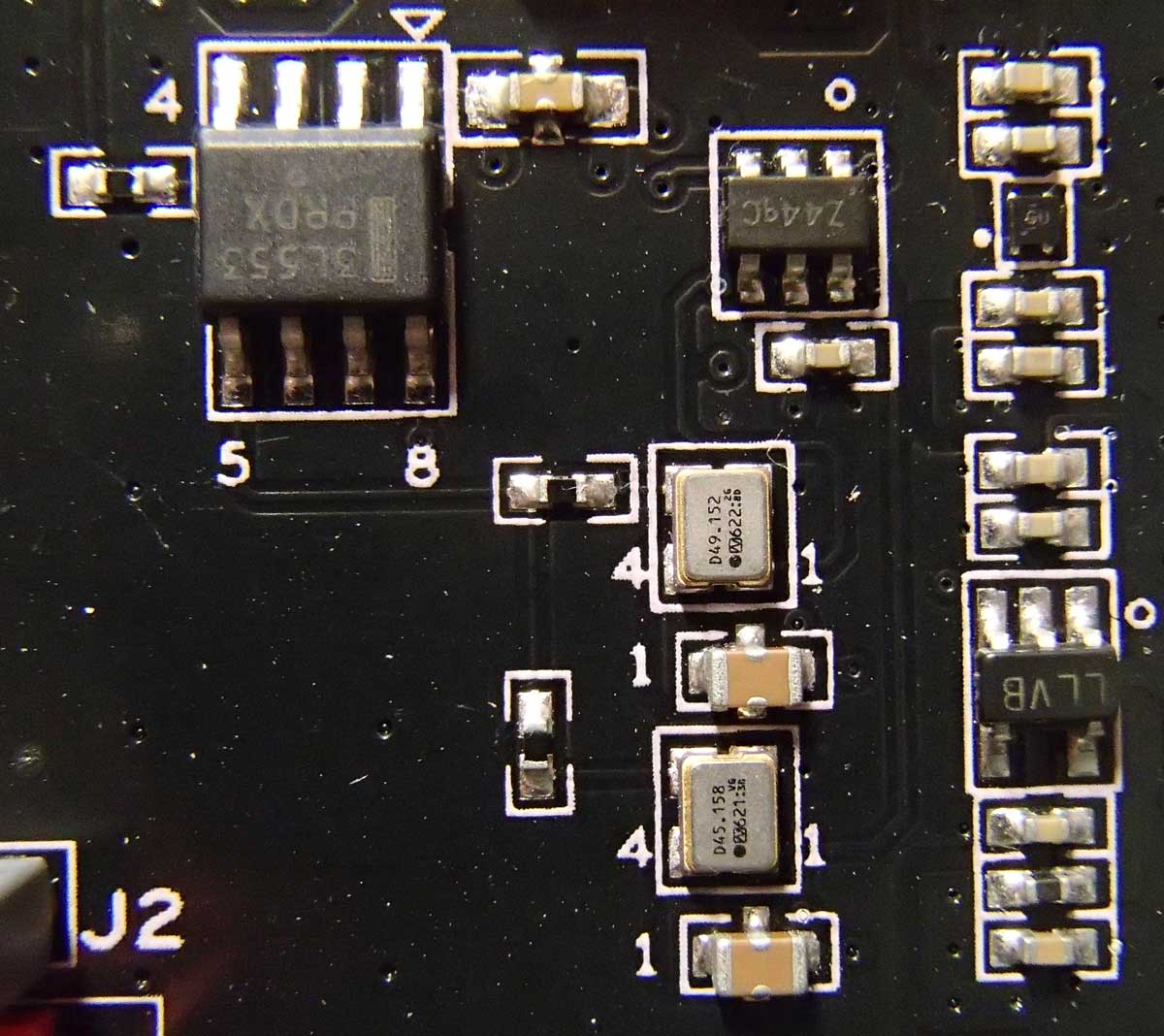
  • Include a new reclocking solution. I went for the best specc’ed chip out there, the famous Potato Semi PO74G374A. One chip would take care of the all of the I2S lines for both DAC chips.
  • Add a couple of external 1.8V DVDD power supplies.
  • Make some optimization of the LT3042 local regulators’ layout, in order to accommodate larger package capacitors (1206) where it would make most sense.
  • Give access to the zero-detect lines of one of the dac chips. These pins could be used to easily implement auto muting of the output stage.
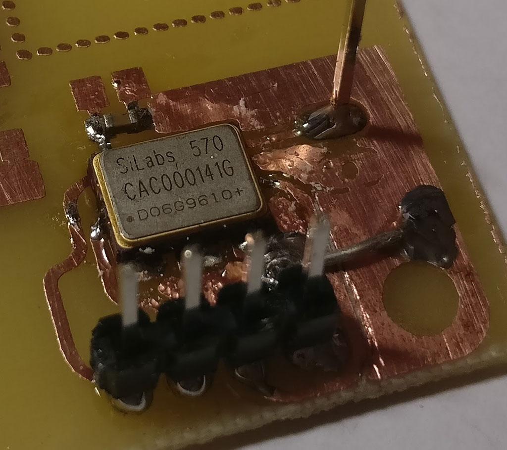
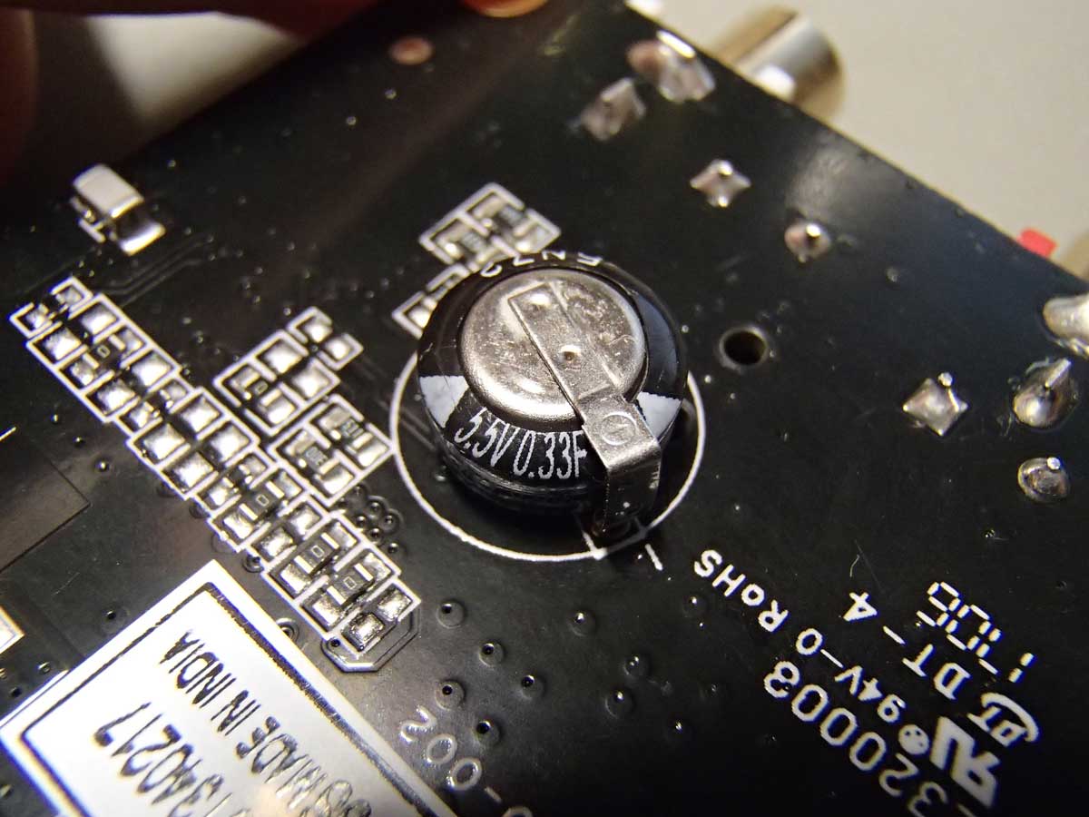
  • Give access to the Enable pin of the Si570/Si544. The use of this Enable pin will be explained later.

In addition I would use the then new Si544 programmable oscillator, offering improved performance over the Si570. This did not require any changes to the pcb.

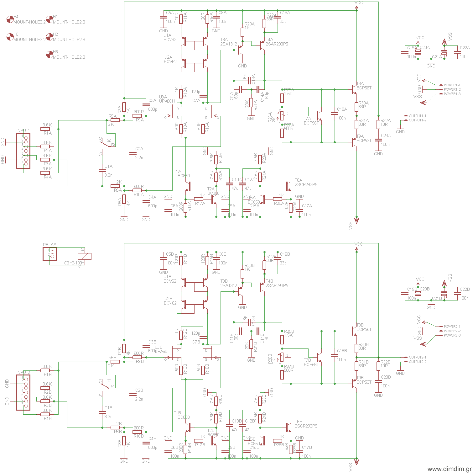
This is the updated schematic:

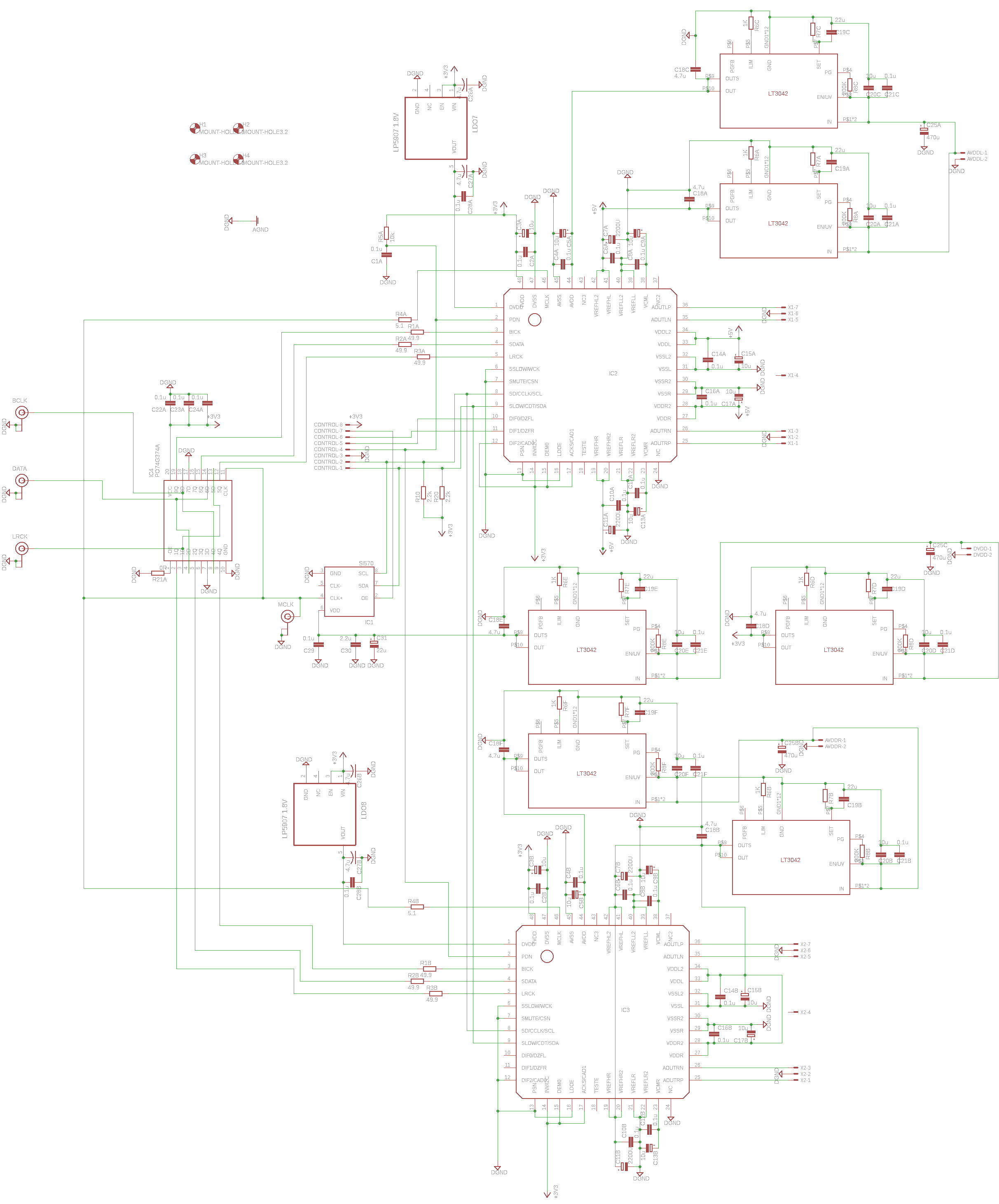
(Right click, Save Image As.. to download it in full resolution)

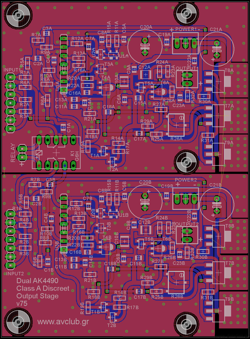
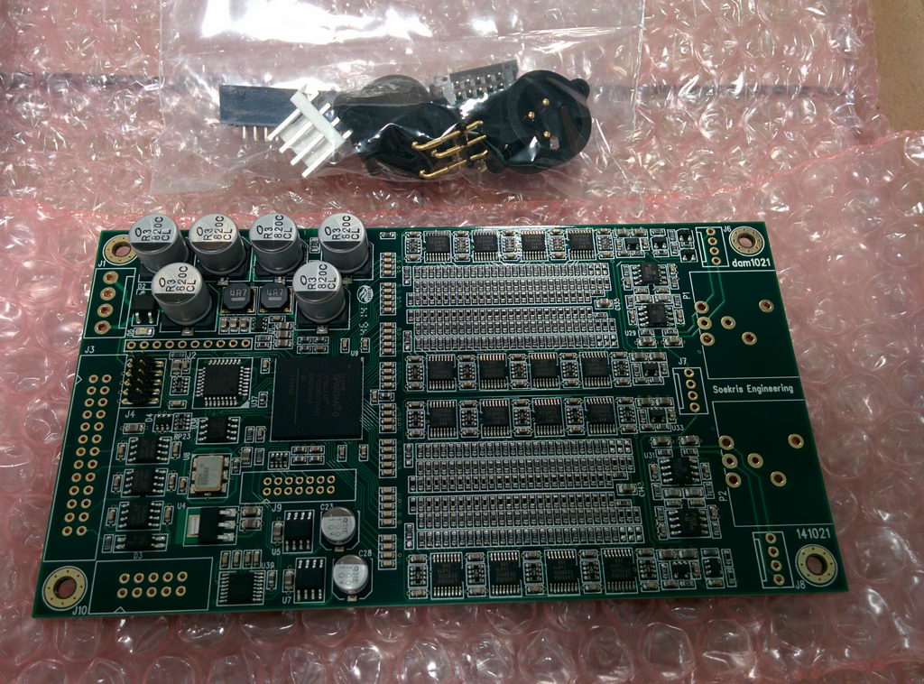
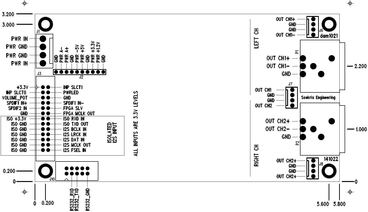
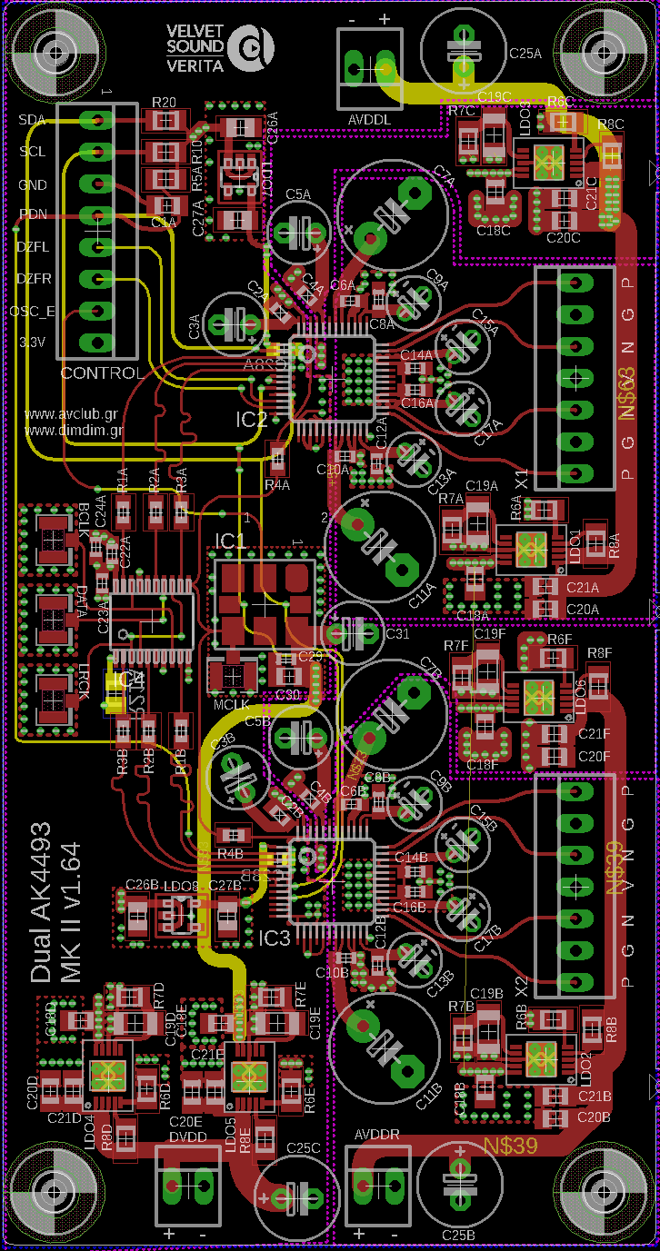
This is the 4-layer PCB:

And this is the BoM (v1.9) in xls format: Dual AK4493 DAC (main board BoM) (11086 downloads )

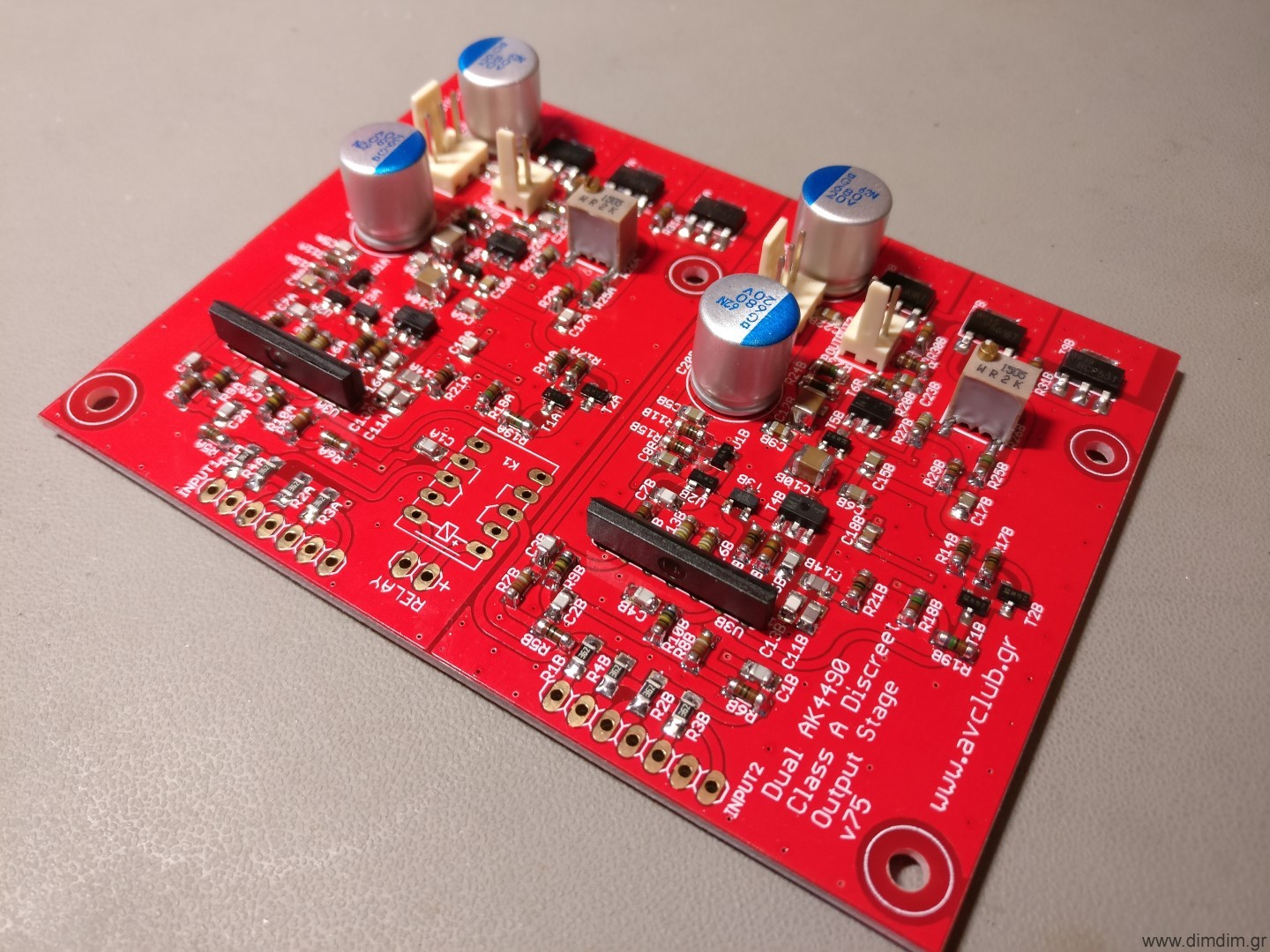
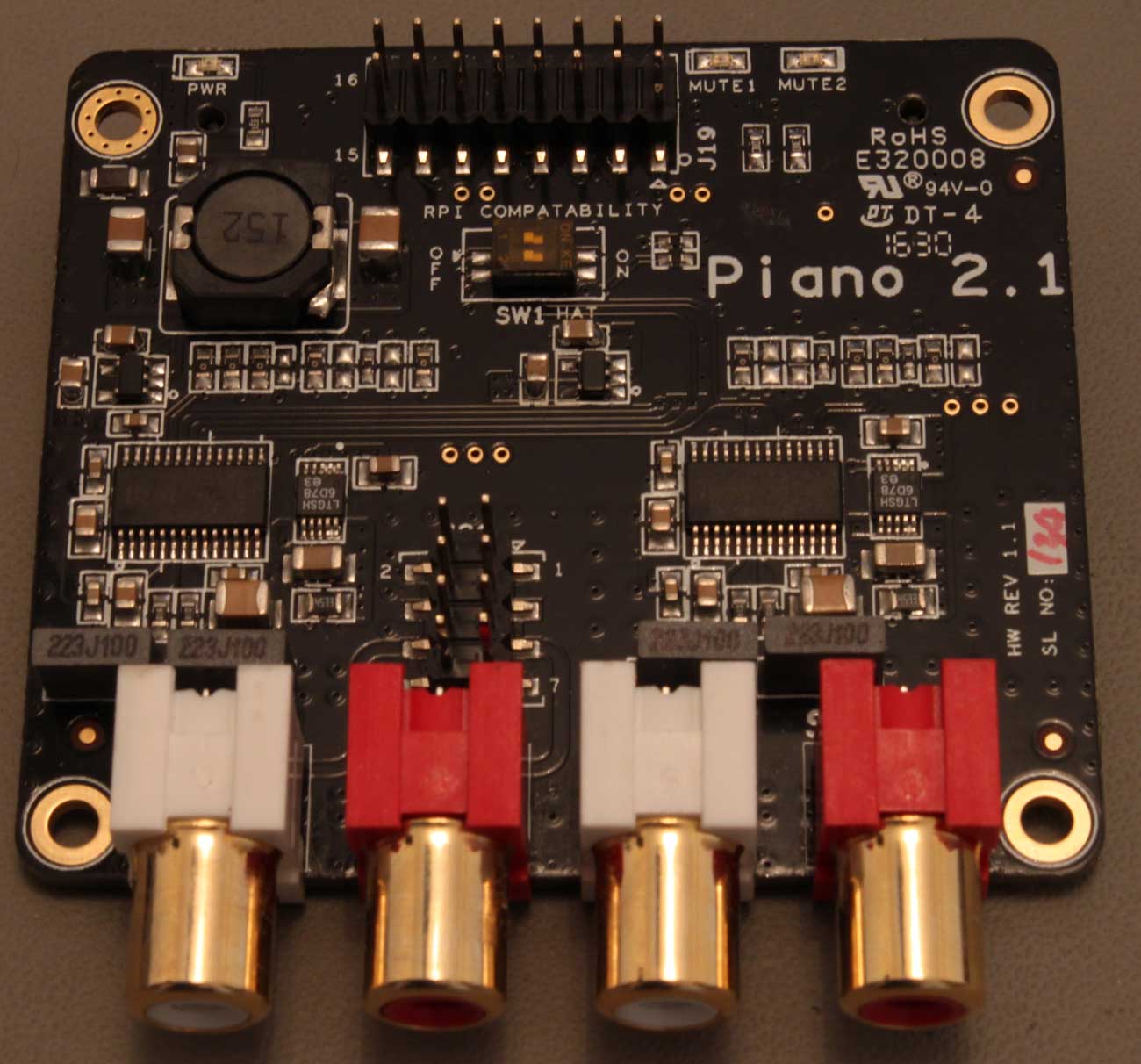
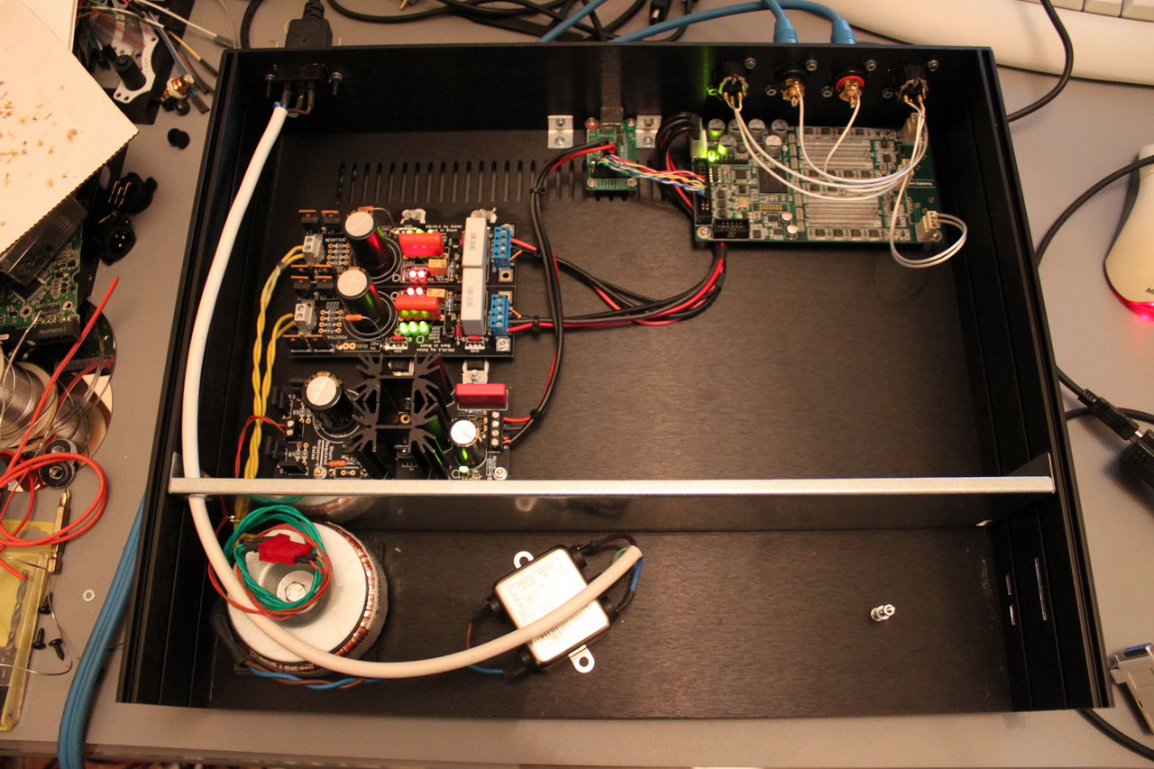
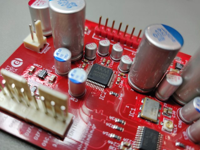
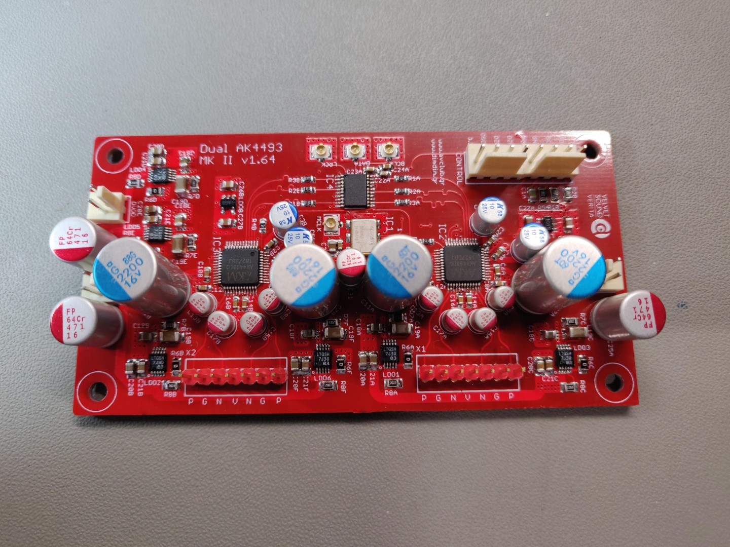
The finished board looked like this:

The design consideration, powering scheme and clocking considerations remain the same as with the original design. There is not much sense in repeating the same text here. I will make a few notes though, based on the experience gathered from building, testing and listening to several such DACs.

  1. Reclocking is indeed a good idea, offering both measurable improvement in jitter as well as better sound quality.
  2. The pre-regulators that power this board matter. A lot. Especially the ones for AVDDL & AVDDR. We got the best (audible) results by using a couple of paralleled LT3045s.
  3. In a resolving system, any change in anything makes audible differences. I was particularly surprised to hear how much of a difference having correct (and uniform across my devices / stereo components) electrical phase in my power cords made.

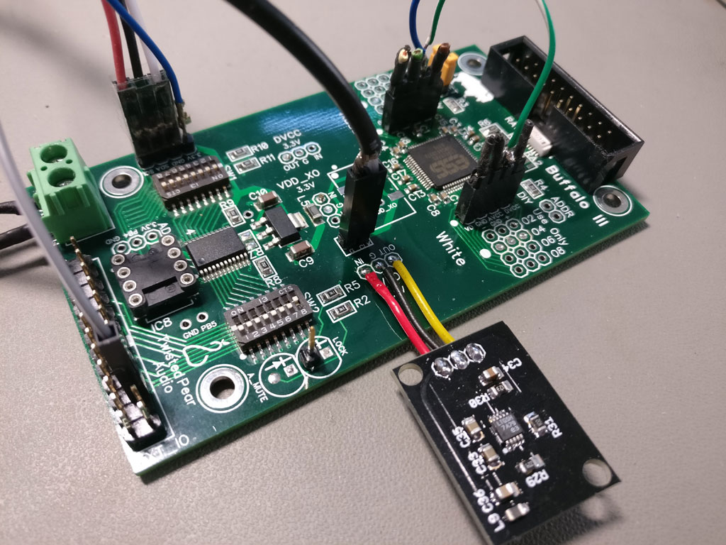
Also, having a properly designed and implemented USB to I2S receiver is very important. Early on I realized that it would be best if I designed my own XMOS-based receiver board, custom tailored to my needs. It would also include some light USB line conditioning and an AK4118-based S/PDIF receiver with 4+2 inputs. I would then standardize my DAC designs with this inputs board in mind, including properly supporting it in my Arduino code.

And so this board came to be:

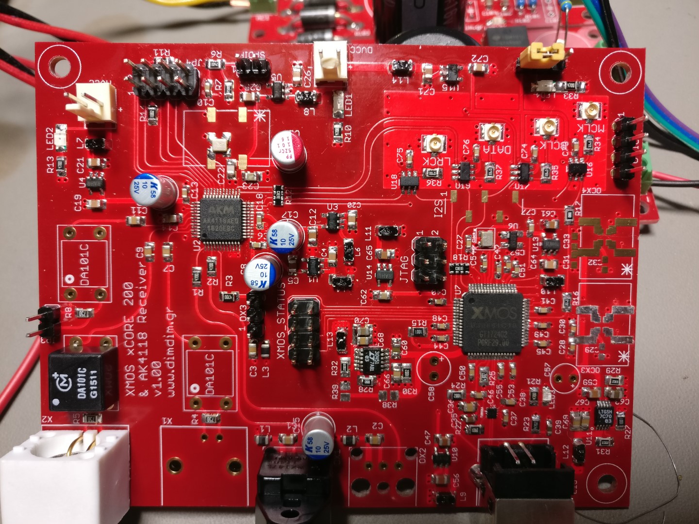
Describing in detail this board is beyond the scope of this post, but suffice it to say, building it is not for beginners. Plus you will need XMOS’ xTAG programmer to burn firmware into the XMOS chip. If anybody is feeling particularly adventurous, drop me a line and I’ll see if I have any PCBs left.

Now, regarding the Arduino code needed to control this board(s), it is not very different than that used to control the AK4490s. The main differences are:

  • It has been adapted to enable the AK4493s’ PCM/DSD auto detection feature
  • It has support for all of the AK4493’s digital filters
  • It has support for triggering a muting relay
  • It now supports the Si544 instead of the Si570
  • It offers full compatibility with my XMOS / SPDIF board.

There are a number of to-do’s though, such as displaying the bit depth of the incoming PCM signal (from the USB port), plus more information on the incoming DSD stream (such as whether it is in DoP or Native format).

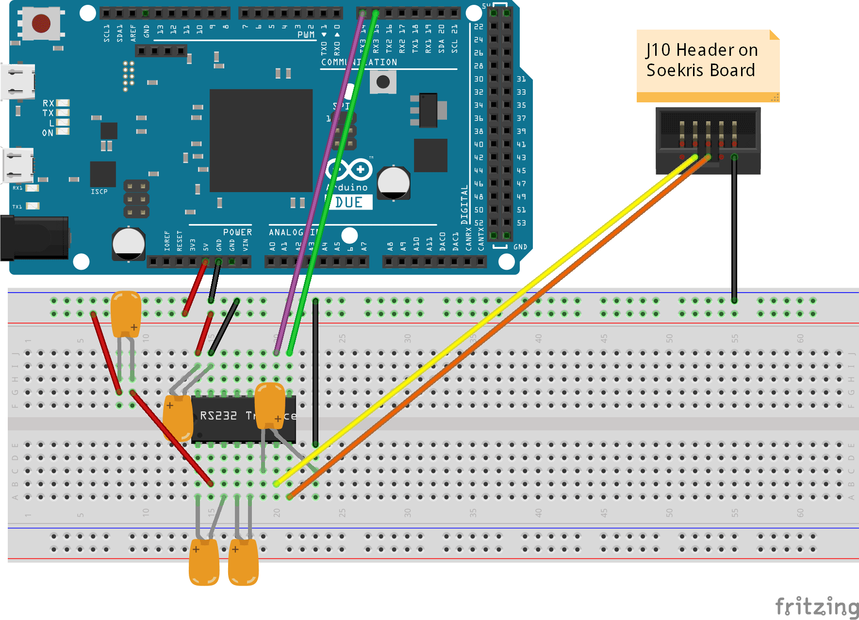
The hardware of the controller is the same that was used with the Dual Mono AK4490 DAC.

In this download I am including the modified versions of the libraries (as mentioned in the above linked post) as well as the necessary font files. Be sure to extract the contents of “Libraries (place in Libraries folder)” to your Arduino IDE’s “libraries” folder.

Download it here: aKduino v3 (30789 downloads )

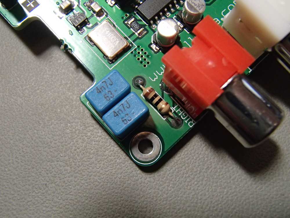
Regarding the output stage, it is the same design that was used for the AK4490 DAC. However its output level is slightly lower than that of the AK4490 board since the AK4493’s VREF voltage is limited to 5.25V, compared to about 7V of the AK4490. This difference in volume is easy to compensate for by changing a few resistors on the output stage.

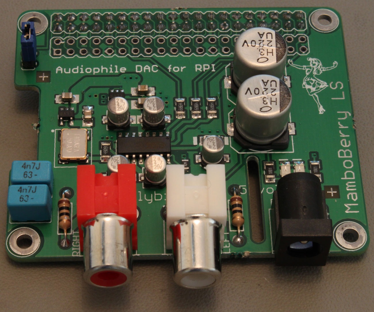
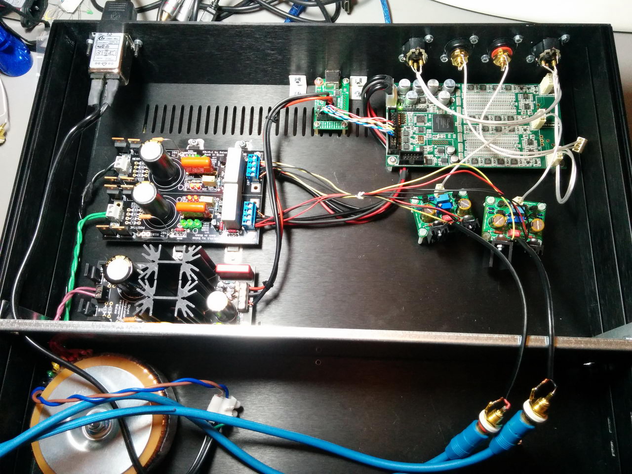
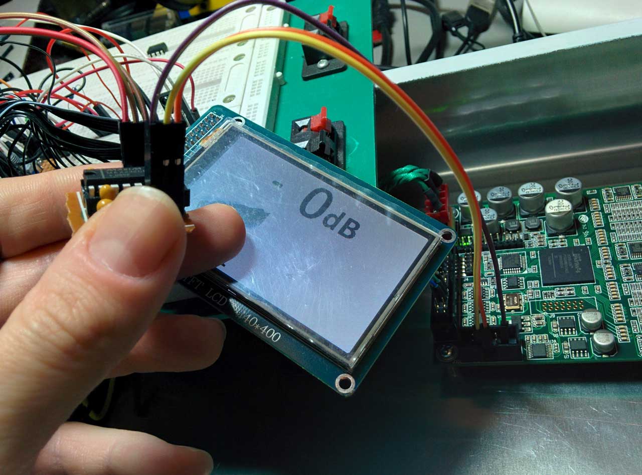
Here is a pic of the 3 boards in action:
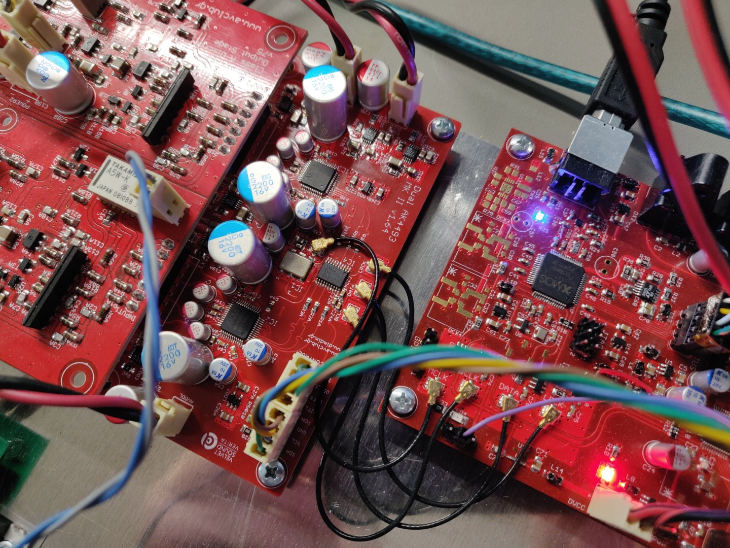
At the time of this writing there have been built 4 DACs based on this updated DAC design PCB.

If anybody is interested in building this DAC drop me a line. I have a few spare boards lying around.

The Raspberry Pi 4 Model B: Game changer for audio?

About a month ago the Raspberry Pi 4 was announced, pretty much blind-sighting everybody.

For the last (many) years, since the announcement of the RPi 2, we had been used to relatively minor incremental upgrades every time a new RPi came out.

Usually the new processor was a bit faster, we got WiFi and BT, then better WiFi, then faster (almost) GbE network, etc. But until now, all of these connectivity options had to be accommodated by a single USB 2.0 port on the SoC.

But this year everything changed. We got a new SoC (the BCM2711), one that finally supported an RGMII interface for a true GbE port, plus a PCI Express port that is used to give USB 3.0 & 2.0 connectivity at useful speeds.

We also got more processing speed and more RAM options, up to 4GB of fast LPDDR4 memory, dual HDMI outputs, etc.

So, all of the above specs mean that the RPi is definitely faster and more capable than ever as a desktop replacement. But is it indeed a better audio streamer for us audiophiles?

For starters, it’s been almost a month since its announcement and availability (I got my unit delivered just 3 days after its announcement) and AFAIK the well-known audio distributions do not yet support it.

Then there is the increased system complexity and power consumption that comes with the new architecture. More power consumption and more ICs usually mean more noise. More noise is never good news for audio.

So I had to do some testing. The idea was to compare the RPi 3 that I had for a couple of years now to the RPi 4.

To keep the playing field as level as possible both of them were running the exact same software (Raspbian Buster Lite, since ATM that is pretty much the only OS that supports both of the platforms) with MPD loaded and were powered by the same (excellent) Salas L-Adapter power supply.

Connection to my DAC (DIY dual AK4493, very detailed) was through USB 2.0.

The music streamed from a NAS box over Ethernet.

I had a friend over in order to at least try to have a bigger sample size (of ears).

The music used was a handful of tracks that we always use for such comparisons (well known material).

We listened using the RPi3, then shut it down and booted up the RPi4, listening to the same material.

Much to our surprise, we actually preferred the sound of the RPi3!

The RPi4’s presentation had something of a “fatiguing” effect. The sound was a bit more “coarse” that that of the RPi3.

We are not talking about big differences here, but they were there. Note that my system is pretty resolving, every change to any component is audible, so YMMV.

I’m not saying that my (our) results are 100% conclusive, but in any case it seems like I’ll be going ahead with my “Audio Pi” project after all (I was considering waiting for the Compute Module 4 to come out).

Soekris dam1021 Frequently Asked Questions & Resources

It’s been almost 3 and a half years since the introduction of the dam1021 to the DIY audio community.

In these 3 years there have been sold close to 2500 units (according to a serial no. that I noticed on a picture of a rev.5 unit) that have made a large number of audiophiles very happy.

The dam’s main thread at diyaudio.com is about 740 pages long, and while the first post has been edited to keep the specs and the firmware info up to date, there are still certain questions that keep popping up over and over again.

In this post I’ll try to address as many of them as I can.

F.A.Q.

Q: Where can I get firmware, manuals, etc?
A: http://www.soekris.dk/download.html

Q: What are its power requirements?
A: According to the manufacturer, power should be supplied by a transformer with two secondaries at 7 to 8 volts AC. The transformer should have a rating of at least 5VA. Alternatively, you may power it by a bipolar DC power supply outputting between +/-7.5 and +/-15 Volts. Power consumption is ~160mA for the positive rail and ~60mA for the negative.

Q: Does it support DSD?
A: Yes, DSD64, DSD128 and DSD256 (only native) has been supported since firmware rev. 1.06 (released May 2016) through the I2S input. DSD does get converted to PCM in order to be converted to audio by the R2R ladder (obviously.. we’re talking about an R-2R DAC).

Q: How do I control input selection?
A: Input selection is done either by connecting switches to J3 (see manual for more details) or by commands sent through the dam’s serial ports. There also exists an “auto input selection” feature.

Q: How do I control volume?
A: Either by connecting a pot to the relevant pins on J3 (see manual) or by commands sent through the serial ports.

Q: What if I want to add IR remote control?
A: You’ll have to use a microcontroller like an Arduino. I’ve done two such projects, ArDAM1021 and ArDAM1021 Lite.

Q: How do I upload new firmware?
A: Through the serial port(s). See: https://www.dimdim.gr/2015/02/soekris-r-2r-firmware-upgrade/

Q: What is the latency from digital input to analog output?
A: About 1mS. link

Q: How come the new firmware (rev. 1.19) does not play as loud as the older firmwares?
A: According to the manufacturer “The new 1.20 firmware and 4K filters have zero at -2 dB, the dam1021 then add 1 dB gain, resulting in zero at -1 dB with 1 dB margin, ie when volume level is set to 0 then it’s 1.26V rs output at resistor network, about 1.9V at buffered single ended and 3.8V buffered balanced.” link

Q: Is there a way to run truly “NOS”?
A: Yes: http://www.diyaudio.com/forums/digital-line-level/269776-filter-brewing-soekris-r2r-post5452884.html  ???  Beware that the specific filter is not compatible with the current DAM firmware (rev 1.19), since it now supports 4K taps (it used to support 2K taps).

Q: Can I use a pair of them as a 2-way digital crossover?
A: Yes, in theory you can, but it’s not fully supported by the manufacturer. Read below to understand why that is so.

Q: Can I sync several DAMs, for example to implement a digital crossover?
A: According to the manufacturer “multiple dam1021 running on same clock will sync to within a few uS” link

Q: How do I actually implement the HP and LP filters?
A: You need to design your own custom filter files and load them. “the dam1021/dam1121 have the hardware with support for up to 15 IIR biquad filters per board” link Not for the faint of heart.

Q: I have “ Rev x”, do I need to do power mods?
A: If you have a Rev. 1 board you do need to perform the mods. Later revisions are OK. Rev. 5 has 20 x 100uF Samsung caps so definitely no need for power mods. link

Q: What can I do to make the DAM sound better?
A: a) Don’t use the buffered outputs. Their SQ is inferior to the unbuffered outputs.
b) Use a proper power supply. The better the PS, the better the sound. In my experience, the best one so far is the Salas UltraBiB.
c) Use a custom filter pack. Beware that custom filter packs may not support DSD or take advantage of the increased available number of taps made possible by the latest (rev 1.19) firmware.
d) Be sure to insulate the screw mounting holes from the (grounded) chassis by using non-conductive screws or some other method.

Q: I’m feeding my dam1021 audio from my RPi’s I2S output. Why does some music play fine while some does not?
A: Most audio RPi distributions output whatever they find in the music file without altering it, like for example a 44.1K/16bit FLAC file will produce a 16bit I2S signal. But the dam1021 only supports 32bit I2S signals. The solution is to force the RPi to only output 32bit I2S. Different audio distributions have different ways of accomplishing that.

Q: What does the dam1021’s output buffer schematic look like?
A: The circuit has changed since the first revision. The current (rev.4&5) circuit looks like this: http://www.diyaudio.com/forums/vendor-s-bazaar/259488-reference-dac-module-discrete-2r-sign-magnitude-24-bit-384-khz-post5347636.html


Resources

Official thread on diyaudio.com: http://www.diyaudio.com/forums/vendor-s-bazaar/259488-reference-dac-module-discrete-2r-sign-magnitude-24-bit-384-khz.html
Filter brewing thread: http://www.diyaudio.com/forums/digital-line-level/269776-filter-brewing-soekris-r2r-147.html
Soekris’ DAC implementations : http://www.diyaudio.com/forums/digital-line-level/267948-soekris-dac-implementations.html
Wiki: http://www.diyaudio.com/wiki/Soekris_R2R_DAC?
HiFiDuino : https://hifiduino.wordpress.com/
Randytsuch : http://randytsuch-audio.blogspot.com/2015/11/soekris-r2r-dam-dac.html
moredamfilters.info: https://web.archive.org/web/20161025204639/http://www.moredamfilters.info/

..and of course my posts about the dam1021:

Main Soekris DAC page: https://www.dimdim.gr/diyaudio/soekris-dam1021-sign-magnitude-r-2r-dac/
dam2012 s/pdif inputs board page: https://www.dimdim.gr/diyaudio/soekris-dam1021-spdif-usb-board/
ArDAM1021 page: https://www.dimdim.gr/arduino/ardam1021-project/
ArDAM1021 Lite page: https://www.dimdim.gr/arduino/ardam1021-lite-project/
dam1021 Vref mod : https://www.dimdim.gr/2015/09/soekris-dam1021-vref-mod/
dam1021 firmware update info : https://www.dimdim.gr/2015/02/soekris-r-2r-firmware-upgrade/

Let me know if I missed anything (I’m sure I did..).

I’ll try to keep this FAQ updated.

Arduino controlled Dual Mono AK4490 DAC (Part 3)

Following up on Part 2, it’s time to talk about the output stage.

This output stage is the brainchild of my friend Kostas, all I did was lay out the PCB.

It is a fully discreet single-ended class-A output stage, outputting ~2.4V RMS.

This is its schematic:

This is the PCB:

And this is the BoM: AK4490 dual mono DAC - Discrete Analog stage BOM (89316 downloads )

The BoM includes part numbers for most parts from Mouser. The only parts that are not in production and must be found elsewhere are the UPA68H. Ebay is a good bet. Chances of getting fake parts are pretty small, but just in case do this to double check the ones that you bought: http://www.diyaudio.com/forums/analog-line-level/296406-salas-dcg3-preamp-line-headphone-post5330311.html (Thank you Salas for the info and the idea to use them in the first place!)

The only parts that need matching are T8A with T9A and T8B with T9B. There’s no need to go crazy with the matching – within 5% should be enough.

Power should be ideally +/-16VDC. A bit less is OK (I did my initial testing with +/-12VDC) but more will most likely damage the board. The board is running in class-A so current draw is constant. A power supply with 100mA current capacity should be enough.

Bias current is adjusted by the multi-turn trimmers R26A and R26B. They should be adjusted to their mid value before soldering to the board (~1K). To adjust bias just measure current consumption at one of the rails while turning the pot. Adjust for ~25mA total current draw per rail and per channel. Current draw on the negative rail should be about 1mA higher than on the positive rail. Bias should be re-adjusted if the power supply voltage needs to change.

After bias adjustment and with no input signal you should check for DC at the outputs. If everything went well you should be seeing anywhere between 0 to a few mV of DC voltage.

A few design notes:

  • This design is inverting. I’ve set up my AK4490 code to also invert the 4490’s outputs so as to end up with a non-inverting overall output. But it doesn’t seem to be making much of an audible difference, since I can’t hear a difference as I’m switching between inverting and non-inverting output.
  • There is provision for a relay that switches between the default filter for PCM (-3db @ ~90KHz) to a more proper filter for DSD (-3db @ ~50KHz). This feature has not been tested yet..

Regarding the resistors, we’ve chosen to go with mini MELF resistors (type 0204) because of their high quality and in general excellent reputation for audio. We are aware that some of the necessary values ATM are kind of hard to source so we’ve included notes in the BoM with the really critical parts and valid value ranges for the less critical other values. Note that “+/-5% from initial value” does not mean that the parts tolerance can be 5% – it means that instead of for example a 10K resistor you can use a 10K + 5% = 10.5K part. It still has to be matched to its counterpart, of course.

I am including these substitutions, as reference:

Instead of the proposed 604R : —-> https://gr.mouser.com/ProductDetail/Vishay-Beyschlag/MMA02040C6190FB300/?qs=sGAEpiMZZMsU0eETUM64Jwu1lXnAfA1Az%2fUBmHPWxBQ%3d
Instead of the proposed 62R —-> https://gr.mouser.com/ProductDetail/Vishay-Beyschlag/MMA02040C5909FB000/?qs=sGAEpiMZZMsU0eETUM64JzhzDaxYafIopmV6xoU7Pd%2faEeFyYr39dw%3d%3d
Instead of the proposed 49,9R —-> https://gr.mouser.com/ProductDetail/Vishay/CMA02040X3909GB300/?qs=%2fha2pyFaduinSoUQ%252bxM%252bcspKJgxV2WgydeZC1mFkJQ0%3d
Instead of the proposed 499R —-> https://gr.mouser.com/ProductDetail/Vishay-BC-Components/CMA02040X4700GB300/?qs=sGAEpiMZZMsU0eETUM64J9XrXp4g00LTnadULizxluo%3d
Instead of the proposed 33R —-> https://gr.mouser.com/ProductDetail/Vishay-Beyschlag/CMA02040X3309GB300/?qs=sGAEpiMZZMsU0eETUM64J5DAE%2fHuiq02KfqnEeQjWns%3d
Instead of the proposed 10R —-> https://gr.mouser.com/ProductDetail/Vishay-Beyschlag/CMA02040X1009GB300/?qs=sGAEpiMZZMsU0eETUM64J5wRh77yguxgpX8F3yMYvKE%3d

The value of two of the required 1K resistors (the R20A & R20B) is critical, so you should use these —-> https://gr.mouser.com/ProductDetail/Vishay-Beyschlag/CMA02040X1001GB300/?qs=sGAEpiMZZMsU0eETUM64J5DAE%2fHuiq026nqxTapoB%252bc%3d
for the other 6 non-critical 1K resistors you can use these —-> https://gr.mouser.com/ProductDetail/Vishay-Beyschlag/CMA02040X1201GB300/?qs=sGAEpiMZZMsU0eETUM64J5DAE%2fHuiq02Tdrq8lX57XI%3d

The value of the 120R resistors is critical, so are the tolerance of the 49.9R (substitution for 39R) resistors. Their values should be matched.

This concludes Part 3. The next post will detail how everything works together.

Yes, I put an ES9028Pro on my Buffalo III

A few years back I was hit by Murphy and I was hit hard.

It was the time when you had to be very patient and even somewhat lucky if you wanted to buy a Buffalo DAC. You had to wait for the boards to go on sale and then be quicker than the other (equally “DAC hungry”) DIYers for the privilege of owning one.

I had just gone through all of that trouble and had managed to acquire a brand new Buffalo III board. I remember it like it was yesterday, even though it’s already been more than 5 years. I had it connected to my bench top power supply and was just doing a dry-run, I hadn’t even built the IVY-III yet, looking to see that everything was working as it should, when all of a sudden the lights on the Tridents all went very bright for half a second and then the magic smoke escaped. My power supply’s regulator IC had chosen the worst possible time to kick the bucket. Cost of repairing the power supply: ~1€. Cost of getting a new B3: ~400€ plus another 2 months of waiting.

An autopsy of the damaged board confirmed my suspicions: Almost every active component on the board was gone. Besides the Tridents and the AVCC module, the ES9018S and the Crystek clock were toast. The only components that survived were the ones behind the 3.3V regulator, which proved to be resilient enough to withstand the ~35 volts that were fed to it. So the cost of repair would be prohibitive, especially considering that I couldn’t find anyone that would sell a single ES9018S chip. So the bad board went into a cardboard box and lay there for close to 5 years.

Fast forward to 2016. ESS announces the successors to the ES9018S, the ES9028Pro & ES9038Pro chips.

These chips have a brand new digital core, much improved from the ES9018. There are new digital filters, a new DPLL system, new THD compensation features, a new gain compensation function, etc.
The ES9028Pro is supposed to be an ES9018S with an updated digital core, while the ES9038Pro is supposed to be an ES9028Pro with 4 times the output stages, resulting in an extreme output current capability. This very high current would be the reason why its DNR and THD+N performance would be off-the-charts. But it also meant that all of the existing I/V stages that were designed for the ES9018 would not work for the ES9038Pro. As of this writing, neither Twisted Pear Audio or Acko have on offering proper I/V analog stages.

I made this little table to give you a better idea of the differences between the old and new chips:

[table “” not found /]

* up to 13
** most likely an error in the datasheet

This info comes from the official brochures that are available on-line, with some additional info from the NDA-protected “full” datasheets. ESS, if you are reading this (and you probably are), there really is no point in trying to keep these datasheets secret. If someone like me (with my non-existant connections) can find them, so can your competitors. Plus I can’t really say that I found any content in your datasheets that would warrant such extreme measures. But I digress.

So, upon inspection of the datasheets the first thing one notices is that both new chips are pin to pin compatible with the ES9018S. That was just too convenient for me and my bad Buffalo board. Good job ESS, I really appreciated that. 🙂 🙂

On the software side, things were very different to the ES9018S. The number of registers had more than doubled (48 registers in the ES9018 versus 115 in the ES9028/38) plus their arrangement was totally different, so I would need to do a total rewrite of the code to support it. Good. More fun to be had. 😀

So now a lightbulb had lit up in my head. I didn’t have much to lose – I already had the board, I could hook up temporary power supplies and a temporary clock so all I had to buy was the actual chip. Considering that I would like to be able to use my existing analog stage, I chose to go with the ES9028Pro. I got on Ebay and ordered a couple (a friend had also decided to bite the proverbial bullet and do the same “mod” to his Buffalo).

Next up was power requirements. The required voltages are the same but the required current has doubled or even tripled, depending on which chip we are talking about. That could be a problem for the AVCC module and Tridents of the Buffalo 3. I needed to do some reading-up on the AVCC & Trident modules. It turns out that the Trident modules are capable of supplying up to 100mA of power (with the proper CCS resistors) so in theory they could be made to work. But my (burnt) Tridents were v1.1, meaning that they were not exactly famous for their robust-ness. Asking them to work near their thermal limits would be looking for trouble. Plus, while researching the Tridents I learned of their latest version, the Trident SR. These now use ultra low noise LDOs (ADM715x) and are rumoured to sound even better than their older shunt types. These days my ultra low noise LDO of choice is the LT3042 so I drew up a set of PCBs that would be a drop-in replacement for the Tridents & AVCC and made an order to a well-known Far East board house.

While waiting for the chips to arrive I had put together some Arduino code that would initialize the chip and provide some basic functionality. It was nothing special – serial port only – but it would get the job done.

After a few days the ES9028Pro chips came and there was no way I was going to wait another month for the new Tridents.

Off came the damaged components..

..to be replaced by fresh capacitors and the brand new ES9028Pro.

For the time being I chose to not solder on a new Crystek since I could not be 100% sure that the board would work.

Instead, I soldered on a two pin header to which I connected an Si570 programmable oscillator that I had lying around.

Power was to be delivered by the on-board die-hard 3.3V LDO with a little help from a small PCB holding a LT3042 taking care of the 1.2V.

I hooked everything up, connected my Arduino, powered the thing on and loaded an I2C scanner on my Arduino. I did a scan and found a single I2C address. That was not good. I should have found two (one for the on board port expander and one for the ES9028). I double checked my connections, my power, made sure that my Si570 was outputting a proper clock, but still nothing. It was time to go back to the datasheet.

My eye fell on the section pertaining to the Reset pin. It stated that it was an active-low pin and that a system reset could be performed either by pulling the pin low or by a software command. The Buffalo III design called for this pin to be pulled low by default so I hadn’t paid any real attention to it. It turned out that I should have. I soldered a 2 pin header and put a jumper on it. The board immediately came alive and was detected by my I2C scanner. 😀 So, the Reset pin should be pulled up.

With that out of the way, I connected my test I2S source (a Chinese clone of an Amanero – not as good as an original Amanero but OK for testing and pretty expendable). The DAC locked with no problem into all sampling rates up to 352K and DSD128 (I didn’t bother to try to go higher) and started playing music!

Now I’m waiting for the new replacement Tridents & AVCC module PCBs to arrive so that I can do a proper test vs. my Buffalo III.

I also need to do a version of my TFT HiFiDuino code for the 9028/9038. Stay tuned.

Mamboberry LS DAC+ vs. Boss DAC vs. Piano 2.1 Hi-Fi DAC with and without Kali FIFO Reclocker


Back in September Allo.com had sent me their Piano 2.1 DAC along with their Kali reclocker, but I didn’t have any other DAC HATs to compare it to and it wouldn’t be fair to it to compare it to my Soekris or my Buffalo III DACs. This changed this week, when they sent me their new Boss DAC and by happy coincidence I also had the chance to spend a few days with the Mamboberry LS DAC+.

It was showdown time.

Technology

But before I get to the interesting stuff, a few words about the technology used in RPi DAC HATs.

An RPi DAC HAT is fed audio using what is called an I2S protocol. I2S was designed for transferring audio between ICs located on the same PCB, but audiophiles have somewhat stretched its capabilities by using it to transfer audio data between PCBs and some times even between stereo components. It is considered the best, most accurate way to transfer audio data, provided that the I2S signals are properly generated. The RPi has a well-known and documented problem generating proper I2S signals. The problem has remained the same, even though the RPi is now at its 4th generation.

Right now, there exist two ways to deal with this problem:

1) Use some kind of FIFO buffer and reclocker in order to regenerate the I2S signals. Examples of such FIFO reclockers are Ian’s FIFO and allo.com’s Kali. The RPi is configured to output a standard I2S signal and then it’s the job of the FIFO buffer to “fix-up” this signal. The resulting I2S signal is of very high quality, since the FIFO buffers utilize very high quality oscillators and power supplies.

2) Run the DAC in what is called Master Mode. Let’s talk a little more about that.

There are two modes of operation for I2S compatible chips. In case of DAC chips:

Slave mode: The DAC receives all of the I2S signals (BCLK, LRCK and DATA) from the RPi. It is susceptible to jitter since the RPi’s I2S output is problematic.

Master mode: The DAC uses its on-board oscillators to generate the BCLK and LRCK signals, it then sends these signals back to the RPi which uses them to clock its DATA output. This way the RPi does not need to use its own clock, which is problematic for audio use. The end result is an I2S signal of reasonable quality.

Note that not all DAC chips can operate in either of the two modes. Most widespread is the Slave mode, in fact practically all DAC chips support it. The Master mode is supported by a small percentage of DAC chips, like the PCM5xxx series by Texas Instruments or the new ESS DACs (like the ES9038Pro). Well known DAC chips that do not support Master mode include the older ESS chips (ES9018, ES9018K2M, ES9023, etc) and the Asahi Kasei DACs (AK4490, AK4495, AK4497, etc.).

The DACs

With that out of the way, lets see our contestants.

The Mamboberry LS DAC+ is a moderately priced (54.90€) ES9023 based DAC designed to run in slave mode to the RPi. It is considered one of the better sounding HAT DACs out there.

It has an on-board high quality oscillator (by Fox) running at 50MHz (this essentially means that the 9023 is running at asynchronous mode, that is it is resampling all incoming PCM signals), very good quality LDO regulators and passive components.

It may be powered either through the RPi or by an external (preferably linear) power supply. Officially the ES9023 supports sampling rates up to 192KHz but unofficially it goes up to 384KHz / 32bit. It doesn’t really require special software support on the RPi, you just set it for “generic I2S output”.

The Allo.com BOSS DAC is a somewhat pricier (~70€) master mode DAC.

It is based on the PCM5122 DAC, powered by a top-quality LT3042 LDO regulator utilizing DC filtering by very high quality capacitors (including a 330.000uF supercapacitor!).

Clocking is done by a pair of NDK extremely low jitter and low phase noise oscillators (45.1584 & 49.1520 MHz), powered by their dedicated LDO regulator. Their output is buffered by an NB3L553 clock fanout buffer IC which further reduces the jitter.

Sampling rates up to 384KHz / 32bits are officially supported. It’s powered through the RPi, but it has an “Optional 5V battery power in connector” for future use. I suspect that this connector can also be used to power the Boss, but a certain resistor will need to be removed to isolate this power from the RPi. This DAC needs a special driver, since it needs to set the RPi in slave mode and also communicate with it via I2C to set operating parameters and utilize the PCM5122’s hardware volume control. When the DAC is receiving data from the RPi, the indicator “LED1” lights up.

The Allo.com Piano 2.1 Hi-Fi DAC is another moderately priced (~55€) slave mode DAC, based on PCM5142 DACs. Notice the plural.

On board this HAT we have two DAC chips that output a total of 4 channels. Each of the DAC chips also contains a DSP core, capable of doing equalization, filtering or other functions. These DSPs can be configured using TI’s PurePath software, but that is not a trivial task. The distributions that include built-in support for the Piano 2.1 come with a pre-built set of filters, capable of essentially configuring the DAC in 2.1 mode so that it can be used with one or two subwoofers. The analog sections of the DAC chips are powered by two top-quality LT3042 LDO regulators.

There exists no on-board oscillator, since the DACs are running in slave mode. Sampling rates up to 384KHz / 32bits are officially supported. Power is supplied by the RPi. As you can imagine, this DAC also needs a special driver, since it needs to set up the filters in each of the DAC chips plus to utilize the PCM5142s’ hardware volume controls.

A word about audio distributions

There are many audio-oriented distributions available, such as Archphile, RoonAudio, Moode and Volumio. In order to do a fair comparison, I opted to use the same distribution for all tests. The logical choice was Volumio, since it includes proper support for all of our DAC HATs.

Volumio is very easy to install and is very responsive in my RPi3. No complaints whatsoever.

Testing Methodology

The idea was to test the DACs in their default operating mode, that is with no mods and no exotic power supplies. When testing without Kali, the RPi3 & DAC were powered by a 5V 2A SMPS I had lying around from an old tablet. It’s a pretty high quality unit, made by HP. Still, at the end of the day it’s just a wall-wart SMPS.
When testing with Kali, I powered the RPi3 with the same SMPS plus I used an 7805-based linear power supply for the Kali & DAC (jumper on Kali was removed to isolate its power from the RPi’s). Again, nothing exotic. Just a relatively low power (1A max) linear power supply.

After I had an initial listen to all of the DACs in pretty much every possible combination, like “plain DAC” or “DAC with Kali” (where applicable of course) and drawn my conclusions, I thought I would take the system “on tour” to a couple of my friends and their superior sound systems. By doing this I was getting a second and third opinion. So, friend#1’s system is a full-blown MBL installation costing upwards of six figures. His main DAC & transport’s cost is in the 20K range. Friend#2’s system is a more DIY affair, consisting of big (and I mean BIG) Magnepan speakers, diy solid state power amp (several hundred watts per channel, many of them in class A, it makes a lot more than a ding in his power bill), diy preamp, Sony XA50ES modified CD player plus (on loan from me) a Soekris DAM1021 DAC.

At friend#1’s, we used an SPL meter to equalize the volume levels between all of the DACs. We listened to 3 specific tracks. At friend#2’s, we also listened to the same 2 or 3 tracks on all of the DAC combinations but didn’t take much care of level matching. The observations of my two friends were practically the same, so I won’t distinguish between them.

The Results

We started with just the RPi with Mamboberry LS. The sound was OK, not nearly what you would call “hi-end”, but considering the DAC’s cost it was more than satisfactory.
We then moved on to the RPi with the Boss. The improvement in audio quality was more than apparent. The soundstage became better defined, the instruments more clear, the bass just.. more, but in a good way.
Next up was the Mamboberry aided by Kali. Kali did more than just fix up the I2S signal – it also provided clean power to the Mamboberry. Now the Mamboberry began to show its teeth. This combination gave a more clear result than the Boss DAC, like the music became even more life-like. The bass did not have the same authority, but overall the combination Mamboberry & Kali definitely sounded superior to the Boss.
Finally, we teamed the Piano 2.1 to the Kali. The Piano was configured in stereo mode, since there were no subwoofers present. This combination gave the best overall result, giving a more “analog”, musical result. Its sound was the most smooth of all of the combinations, while at the same time it was the most life-like. You could say that it was the least fatiguing of the bunch.

After we were done comparing the HAT DACs, we thought we should listen to our “proper” DACs, just to put things into perspective. To no surprise, both my friend#1’s DAC and my Soekris properly cleaned the floor with the HAT DACs and it’s a good thing that they did – otherwise we would have felt pretty dumb having wasted so much money on so-called “proper” DACs while we could have got the same result with these DAC HATs. Phew.

So, the end result is not really surprising. The more money you spend, the better sound you will get. No giant killers here. But regarding value-for-money, I think that the Boss DAC claims the prize.

Happy π day everyone! 😀

Soekris R-2R: Sound impressions with Salas BiB PS & alpha20 line stage

A couple of days ago I took my DAM and headed out to a good friend of mine to do some listening tests.

My DAM at the moment is powered by a Salas BiB at 12VDC. It has a DIYINHK XMOS based USB to I2S interface powered by a Salas Reflektor-D at 3.3VDC. The same power supply powers the isolated side of the DAM.

IMG_9263_resize(note that this picture is a bit old. I have since swapped the transformer for the one shown in the next picture plus I have used an IEC with a built-in filter)

The first objective was to assess the importance of a good DC power supply instead of a plain transformer. In order to do that I took with me an extra 50VA toroidal with 2 x 7V windings.

My friend’s system consists of Magnepan speakers, a DIY fet-based preamp and DIY power amp (solid state, 60KG monster). It is widely regarded as a very revealing and non-forgiving system. Any change in any of its components (or a component withing the components) is clearly heard.

The DAM was connected to the preamp through its unbuffered outputs.

We gave the system some time to warm up (it was probably a couple of hours) and then sat down to listen. We started with the DAM as it was, with the Salas BiB. We then unplugged the Salas and hooked up the plain transformer.

The change was immediately obvious. The sound thinned, it became more harsh in the high end. It also lost resolution and detail. Going back to the BiB made all the good qualities come back.

Thus, I can definitely recommend a proper DC power supply for the DAM. I cannot say whether it was the Salas that did the work or that any DC power supply would do the same, but the improvement was definitely there. Note that I have the BoM for the Salas BiB I built in the Soekris’ page.

The second objective was to assess the difference that could be made by using a “proper” output stage after the unbuffered outputs.

So I built a pair of AMB alpha20 line amplifiers. I set their gain to 2 and powered them temporarily by the same Salas BiB that powers the Soekris.

2015-03-27 01.36.57_resize

Note that my DAM outputs roughly 1V RMS at its output @ 0db since I’m using a filter that includes attenuation at FIR2 (I can’t really remember which one it is though..). This meant that the alpha20 brought its output to a nice 2V RMS.

Going back and forth between using the alpha20 and just the unbuffered outputs, the conclusion was that the alpha20 removed a small amount of the “magic” of the DAM while not really helping in anything besides output volume. I was hoping that it would help improve the dynamics of the DAM – its Achilles’ heel IMHO. In my friend’s system the DAM sounds “flat” compared to his other sources (a heavily modified Sony 50ES cdp, a Buffalo 3 DAC, and an Aune S16). However, this “flatness” is not particularly obvious in other more forgiving systems.

So, my assessment of the DAM so far is as such: It has great detail, exceptional mid-range, proper bass, it is a little soft on the highs, but its main problem is the dynamics. It can sound a bit “flat”, with this “quality” either accentuated or minimized, depending on the rest on the system.

If there was a way to improve its dynamics, to make it more “aggressive”, it would be a stellar performer (with a proper DC power supply of course). As is, it is just great VFM.

Soekris R-2R: Interfacing to an Arduino

The Soekris dam1021 has a serial port (J10).J10-serial
This serial port serves a number of purposes:

1) It is used for uploading firmware updates via the uManager prompt.
2) It is used for uploading filter values via a software utility (not yet released).
3) Outputting info on currently selected Input, Sampling Rate and Volume level.
4) Controlling things by receiving commands. Up to now, we can select Input and change the Volume. More commands might be added in the future (or already exist, but are not yet documented by Soren).

In order to do all those things, one has to interface to this serial port. In this post I detailed how to interface a computer to this port (so as to perform a firmware upgrade). Now it is time to do the same for a microcontroller, say an Arduino.

The problem is, microcontrollers use different voltage levels compared to the “classic” RS-232 serial protocol. In order to make these different things talk to each other, we need to use what is called an “RS-232 Receiver / Transmitter” IC. Such ICs are pretty commonplace, since they are found inside of most devices that come with RS-232 interfaces. The “classic” IC that is used is the Maxim MAX232. It is very low-cost but it is also an old design, requiring 5V (instead of 3.3) and 5 x 1μF capacitors. There is a much newer version of the chip, the MAX3232, operating with a voltage between 3V and 5V and requiring much smaller caps (0.1μF), but it is not as widely available as the MAX232. Since I was in a hurry to get things up and running, I chose what I could find locally in stock: a MAX232.

MAX232

This meant that I had to power it with 5V and use 1μF tantalum or ceramic capacitors, but what the heck. I was in a hurry.

After reading the MAX323’s data sheet I ended up with this:

RS-232-interface_v2_bb
(click on the picture for a higher resolution version)

You will notice that I am using Serial3 of the DUE to talk to the DAM DAC. Any serial port could be used, but I chose Serial3 because it was practical – it will be easy to route these specific pins on the shield that I am designing.

Once I verified that the above circuit worked, I built it on perfboard to keep handy:

MAX232_interface

The above circuit works in general but has some trouble with the DAM DAC. It works just fine upon power up but at some point loses communication with the DAC. The only way to restore communication is to power cycle the DAC. I am not sure what the problem is, but I suspect that it has to do with the power management features of the ICL3221 chip used on the DAM. I have ordered an ICL3221 to use in place of the MAX232, in hope that everything will work fine when I use this (at least in theory) fully compatible IC.

Stay tuned.

Soekris R-2R: Firmware upgrade

The DAM1021 originally came with FPGA firmware 0.8. Since then Soren has released a new version of the firmware, Rev 0.9.

J10-serial
In order to upload it to the DAC one must connect the DAC to a computer using either a “classic” serial port, like the one found at the back of older computers, or a USB to Serial adapter. Then a cable must be made connecting three pins of the DB9 connector to the connector J10 on the DAC board.

These pictures illustrate the connections that are needed:

RS-232_to_Soekris

RS-232_to_Soekris_2

You use your new cable to connect the DAM to your computer’s serial port (or USB-to-serial adapter). You do not power on the DAM DAC just yet.

Once you are done with making the physical connection, you need to get your hands on some software that supports the XModem 1K data transfer protocol. This is a pretty old protocol, so your choices in software are pretty limited. One such choice is the “classic” HyperTerminal, but since it is no longer available with Windows I chose the more modern ExtraPUTTY. It is a fork of the classic PuTTY telnet/ssl client software that also supports “vintage” transfer protocols such as XModem.

Once you have it installed it is pretty easy to establish a serial connection at 115200, 8, n, 1, as specified by Soekris. You click on the “serial” tickbox and enter your computer’s serial port (in my case it’s COM5) along with the specified speed (115200bps):

ExtraPutty-configuration

You click on “open” and you get a black terminal screen. You now need to power on the DAC. Once you do that, you should get something like this:

ExtraPutty-after-power

This means that everything is fine. You might see an “I0” instead of an “I3”. That is OK.

Now you need to get to the uManager prompt. You type “+++” and wait for a second. You will not see the “+” characters as you type them. That is OK. You will get this:

ExtraPutty-uManager

Now type “download”, followed by Enter. You will see something like this:

ExtraPutty-uManager-send

This means that you have 30 seconds to begin sending your file. To do that you click on File Transfer -> Xmodem 1K -> Send. Select your firmware file and off you go!

firmware upload (crop)

When the transfer completes you will see something like this:

ExtraPutty-uManager-done

One thing – do not forget to give the “update” command once you have uploaded the code followed by a “y” and return.

Next you type “exit” (and Enter) to exit the uManager prompt and you are ready to power cycle the DAC. Once you have done that, you repeat the above steps to get to the uManager prompt and you verify that you have successfully updated the firmware. You should now be at FPGA firmware 0.9!

firmware upload 0.9 installed (crop)

If are having problems connecting, such as getting garbage like this in your serial console:

screenshot terminal jibberish 2

chances are that your USB to serial adapter is not a “true” RS-232 interface, but outputs TTL levels instead. You can confirm that by measuring the voltages between GND and the RX & TX pins. You should be getting zero volts in one case and about -9V in the other. If you are getting 3.3 or 5 volts, your interface will not work with the DAM. You should try to find a proper RS-232 interface.

The Soekris R-2R DAC

The UPS guy just dropped off my brand new Soekris R-2R DAC:

2015-01-30 13.55.04_resize

Also known by the very bland designation “DAM1021”.

It is a sign-magnitude R-2R DAC (a.k.a. “ladder” DAC), meaning that it is quite different in operation than the regular run-of-the-mill DACs.
It is more like a PCM1704-based DAC but with 192KHz+ support plus a bunch of high tech goodies, such as a built-in FIFO buffer.

It is available in three versions, with resistors of different tolerances (0,01% (high grade), 0,02% (mid), 0,05% (basic)). I got my hands on the 0,02% version.

It has three inputs:
1) I2S (electrically isolated)
2) Coax s/pdif
3) TTL for a Toslink receiver

Board-diagram

It is powered directly by a 2 x 7-8V transformer, but may be powered by a bipolar DC power supply.

It outputs a single ended signal at 1.4V RMS and also has a buffer for balanced output at 4V RMS.

It has a serial port for firmware upgrades as well as control.

I have already began work on a Soekris R-2R version of my TFT HiFiDuino Arduino code, tailored to controlling this particular DAC via its serial port.

The board will of course get its own page pretty soon.. Edit: the board now has a page.

To do: hook the board up and actually listen to it play. Stay tuned.