I apologize in advance if this sounds a bit elitist on my part, but it amazes me just how many DIY audio hobbyists need help planning their power supply solutions.
And I’m not talking about “Salas or LPS-1” discussions, I’m talking about “what voltage should my transformer put out” type of discussions.
So I’ll attempt to clear up the basics.
First up, you’ll need to know your load. This means voltage and maximum current requirements. Based on those, you will know what your options on power supplies will be. The options are too many to get into – switching vs. linear, series vs. shunt, LDOs vs. batteries, etc etc.
The point of this post is not to help you select a power supply topology – that decision is largely subjective anyway.
For our exercise, we’ll assume that our load requires a power supply capable of outputting 5V at up to 1A. We’ll also assume that we’ll be making a “classic” LM317 regulator based power supply.
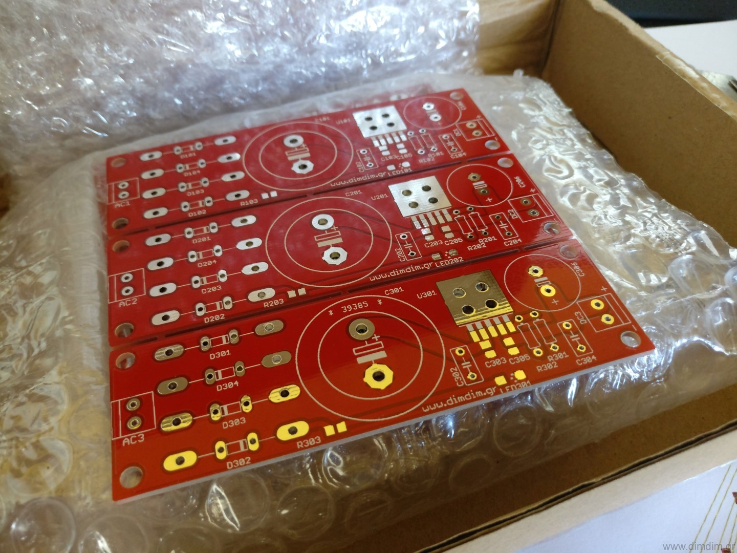
This is the part of the power supply’s circuit that we’ll be focusing on.
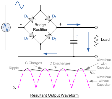
Our task is to select a proper power transformer, rectification stage and filtering capacitor.
Selecting the transformer’s output voltage
Looking at the LM317’s datasheet we see that it requires an input-to-output voltage difference of at least 3V to function properly. This means that in order to get regulated 5V at its output, its input unregulated voltage will need to be at least 8V.
To get 8VDC after rectification and filtering, our power supply will need to supply at least 7V AC. This 7V AC will become 7 x 1.414 = 9.9V – 1.8V (worst case voltage drop on the rectifier diodes) = 8.1V DC.
In real life we will need to take into account possible “sagging” of the power grid by a few volts during certain hours of the day, so it would be a good idea to compensate for that by choosing a transformer with an output voltage slightly higher than the theoretical one. In our case, instead of 7VAC a safer choice would be ~8VAC.
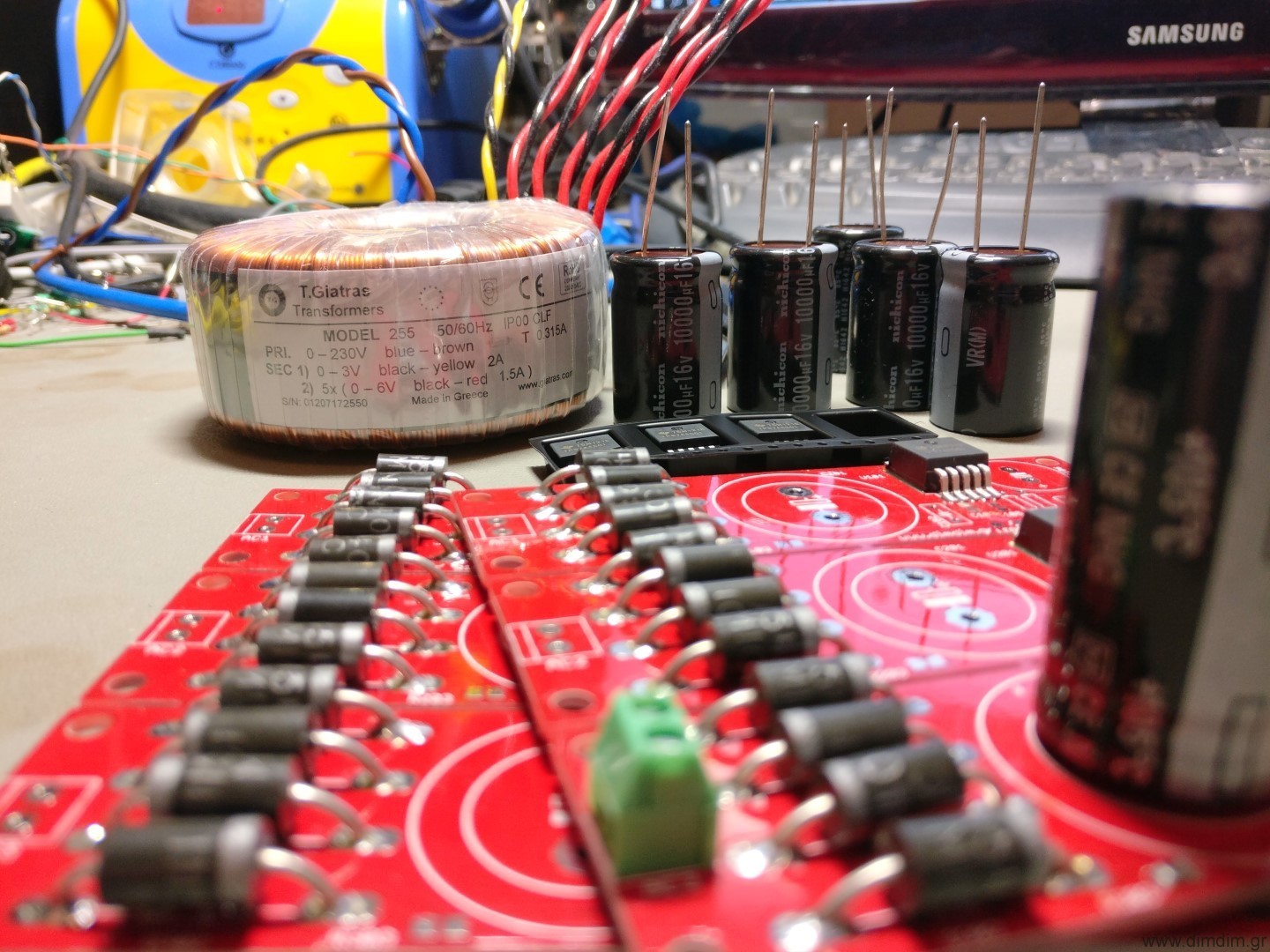
Selecting the transformer’s power rating
Power rating in transformers is expressed as “Volt Ampers” (VA), also known as Watts. It’s the product of the transformer’s output voltage times its rated output current. So a transformer that is characterized as “12V 120VA” is capable of outputting 12VAC at 10A.
Going back to our example, we’ve stated that our load requires 5V at 1A. We have already calculated our transformer’s necessary output voltage to be 8VAC, so 8 VAC times 1A equals 8VA, right? I’m afraid not. This is the most common pitfall for electronics hobbyists when it comes to power supplies. They assume that a transformer rated at 12VAC @ 10A can in fact still deliver 10A after the voltage has been rectified and filtered. But that can not happen. If it did, it would mean that the transformer is outputting more power than what is being put into it.
The thing is, the total power that can be “transformed” by a transformer is fixed, so since the rectification and filtering results in a DC voltage higher than the available AC voltage, the corresponding maximum current must be smaller.
So in our case, to get 1A DC out of our 8VAC transformer we will need a transformer rated for at least 1.5A of current, so 8 x 1.5 = 12VA.
Realistically, to have the transformer running cool and noise-free, we’d double that and go for about 25VA.
Component selection: Rectifier diodes
In order to keep the diodes running cool and reliably you should choose parts rated for at least three or more times your expected load current. This is especially important when building shunt power supplies which draw constantly relatively high currents. For audio circuits opt for ultra fast recovery diodes, such as the MUR series (~25ns). In case of high currents (>1A) be sure to either mount the diodes at least a few mm off the board (in case of radial parts) or use heat sinks (in case of diodes that can accept them). Each diode drops up to about 0.9V, so when they are passing ~1A of current they will need to dissipate almost 1W of heat. That is quite a lot of heat for a small part.
Component selection: Filter capacitor(s)
The filter capacitor is a hard-working component. It has to charge and discharge about 100 times a second (120 times in the US), so as to smooth out the fluctuating voltage that comes out of the rectifying stage. The more current the load is pulling, the harder the capacitor has to work. In our example, since the capacitor is quite possibly charging to the maximum available voltage coming out of the rectifiers, its voltage rating has to be at least (8VAC x 1.414) – 1.8 = 9.5VDC. Taking into account the fact that transformers under no load output a voltage that is higher than their rated voltage, you should go for a capacitor with a voltage rating that is reasonably higher than the minimum required.
Regarding the value of the capacitor, things are just a bit more difficult to figure out, but in the end it all boils down to one thing: how much voltage ripple are we OK with (a.k.a.: is our regulator and load able to tolerate). Once we have determined that, all we need to do is do the math. An excellent description of the theory behind this is this page: http://www.skillbank.co.uk/psu/smoothing.htm
So, C = Iload / 4 * f * Vpk-pk ripple. For example, let’s say that we would be OK with 0.5V ripple. We have: C = 1A / 4 * 50 * 0.5 = 1A / 100 = 0.01F = 10.000uF
One last thing you should keep in mind is the ripple current rating of the capacitor. A good guesstimate is a value at least two times your expected load consumption, but that may vary a lot when you get into high performance audio grade power supplies. For more information (that is beyond the scope of this post) have a look here: http://www.skillbank.co.uk/psu/ripple.htm The spreadsheet linked at the bottom of the page is a great resource.