ArDAM Lite custom PCBs for diyaudio.com

This post serves mainly as a placeholder for the build guide that I wrote for the PCBs, since it seems that some people had problems with the download link that I provided.

The build guide can be downloaded by clicking here: ArDAM Lite Build Guide (44699 downloads )

I do have a few left over PCBs, if you’re interested contact me for more info.

ES9028Pro power wows

Following-up on my previous post, I soldered a Crystek 100MHz clock and had a new set of Trident replacement boards made for my upgraded Buffalo III.

The new boards are direct replacements for the Tridents, supplying 2 x 3.3V for AVCC_L & AVCC_R, 3.3V for the oscillator, 3.3V for the AVDD and 1.2V for DVDD.

Upon powering up the board with the new clock and power supplies, I noticed a problem. Whenever I tried to play material with sampling rate over 44.1KHz, the sound became garbled.

In my test rig I had also used the same power supplies with no problem, so I guessed that the problem had to be the new oscillator. But the new oscillator appeared to be working just fine.

To further complicate things, when I turned off oversampling and the DPLL filter the sound improved (but still sounded bad because I was doing no oversampling).

After some probing and prodding, I realized that my 1.2V supply was sagging below 0.9V when the sampling rates went above 44.1KHz. That should not be happening, since I had set the current limit on my LT3042 regulators to about 125mA with the data sheet specifying the 9028’s 1.2V supply current consumption to 82mA. But it appeared that my 9028 was pulling in a lot more current.

So I disabled current limiting and tried it again. This time everything was working just fine, with no sagging, but my LT was getting hot. Real hot. Like 80 degrees C hot when playing 352.8KHz material. So I did a couple of things. First I desoldered the 1.2V power supply and inserted my DMM in series in order to measure the actual current draw. I got these results:

44.1KHz -> 140mA
DSD64 -> 147mA
DSD128 -> 157mA
352.8KHz -> 200mA

So up to 200mA! No wonder my LT3042 was having a hard time.. I was working it very close to its thermal limits.

I decided to mount it vertically and to add a heat sink to the back of the PCB.

With this arrangement I was getting about 62 degrees C with 44.1KHz material and up to about 75 degrees with 352.8KHz. This is tolerable for 44.1KHz playback but not cool (pun intended 😛 ) for high sampling rates. Since 200mA is pretty much the LT3042’s upper current limit, I’ll have to design a new power supply, either with two paralleled LTs or some other LDO. The bigger problem is the heat dissipation. I will have to make the PCB as big as possible in order to have a lot of room for heat sinking.

But why does this chip’s actual power consumption differ so much from the published specs? As always, the devil is in the details. The stated 82mA is for a sampling rate of 48KHz and a clock frequency of 40MHz. I’m using a 100MHz oscillator so power consumption ought to go up, but I never expected it to increase so much. I wonder what will happen if I input a 768KHz signal.

Yes, I put an ES9028Pro on my Buffalo III

A few years back I was hit by Murphy and I was hit hard.

It was the time when you had to be very patient and even somewhat lucky if you wanted to buy a Buffalo DAC. You had to wait for the boards to go on sale and then be quicker than the other (equally “DAC hungry”) DIYers for the privilege of owning one.

I had just gone through all of that trouble and had managed to acquire a brand new Buffalo III board. I remember it like it was yesterday, even though it’s already been more than 5 years. I had it connected to my bench top power supply and was just doing a dry-run, I hadn’t even built the IVY-III yet, looking to see that everything was working as it should, when all of a sudden the lights on the Tridents all went very bright for half a second and then the magic smoke escaped. My power supply’s regulator IC had chosen the worst possible time to kick the bucket. Cost of repairing the power supply: ~1€. Cost of getting a new B3: ~400€ plus another 2 months of waiting.

An autopsy of the damaged board confirmed my suspicions: Almost every active component on the board was gone. Besides the Tridents and the AVCC module, the ES9018S and the Crystek clock were toast. The only components that survived were the ones behind the 3.3V regulator, which proved to be resilient enough to withstand the ~35 volts that were fed to it. So the cost of repair would be prohibitive, especially considering that I couldn’t find anyone that would sell a single ES9018S chip. So the bad board went into a cardboard box and lay there for close to 5 years.

Fast forward to 2016. ESS announces the successors to the ES9018S, the ES9028Pro & ES9038Pro chips.

These chips have a brand new digital core, much improved from the ES9018. There are new digital filters, a new DPLL system, new THD compensation features, a new gain compensation function, etc.
The ES9028Pro is supposed to be an ES9018S with an updated digital core, while the ES9038Pro is supposed to be an ES9028Pro with 4 times the output stages, resulting in an extreme output current capability. This very high current would be the reason why its DNR and THD+N performance would be off-the-charts. But it also meant that all of the existing I/V stages that were designed for the ES9018 would not work for the ES9038Pro. As of this writing, neither Twisted Pear Audio or Acko have on offering proper I/V analog stages.

I made this little table to give you a better idea of the differences between the old and new chips:

[table “” not found /]

* up to 13
** most likely an error in the datasheet

This info comes from the official brochures that are available on-line, with some additional info from the NDA-protected “full” datasheets. ESS, if you are reading this (and you probably are), there really is no point in trying to keep these datasheets secret. If someone like me (with my non-existant connections) can find them, so can your competitors. Plus I can’t really say that I found any content in your datasheets that would warrant such extreme measures. But I digress.

So, upon inspection of the datasheets the first thing one notices is that both new chips are pin to pin compatible with the ES9018S. That was just too convenient for me and my bad Buffalo board. Good job ESS, I really appreciated that. 🙂 🙂

On the software side, things were very different to the ES9018S. The number of registers had more than doubled (48 registers in the ES9018 versus 115 in the ES9028/38) plus their arrangement was totally different, so I would need to do a total rewrite of the code to support it. Good. More fun to be had. 😀

So now a lightbulb had lit up in my head. I didn’t have much to lose – I already had the board, I could hook up temporary power supplies and a temporary clock so all I had to buy was the actual chip. Considering that I would like to be able to use my existing analog stage, I chose to go with the ES9028Pro. I got on Ebay and ordered a couple (a friend had also decided to bite the proverbial bullet and do the same “mod” to his Buffalo).

Next up was power requirements. The required voltages are the same but the required current has doubled or even tripled, depending on which chip we are talking about. That could be a problem for the AVCC module and Tridents of the Buffalo 3. I needed to do some reading-up on the AVCC & Trident modules. It turns out that the Trident modules are capable of supplying up to 100mA of power (with the proper CCS resistors) so in theory they could be made to work. But my (burnt) Tridents were v1.1, meaning that they were not exactly famous for their robust-ness. Asking them to work near their thermal limits would be looking for trouble. Plus, while researching the Tridents I learned of their latest version, the Trident SR. These now use ultra low noise LDOs (ADM715x) and are rumoured to sound even better than their older shunt types. These days my ultra low noise LDO of choice is the LT3042 so I drew up a set of PCBs that would be a drop-in replacement for the Tridents & AVCC and made an order to a well-known Far East board house.

While waiting for the chips to arrive I had put together some Arduino code that would initialize the chip and provide some basic functionality. It was nothing special – serial port only – but it would get the job done.

After a few days the ES9028Pro chips came and there was no way I was going to wait another month for the new Tridents.

Off came the damaged components..

..to be replaced by fresh capacitors and the brand new ES9028Pro.

For the time being I chose to not solder on a new Crystek since I could not be 100% sure that the board would work.

Instead, I soldered on a two pin header to which I connected an Si570 programmable oscillator that I had lying around.

Power was to be delivered by the on-board die-hard 3.3V LDO with a little help from a small PCB holding a LT3042 taking care of the 1.2V.

I hooked everything up, connected my Arduino, powered the thing on and loaded an I2C scanner on my Arduino. I did a scan and found a single I2C address. That was not good. I should have found two (one for the on board port expander and one for the ES9028). I double checked my connections, my power, made sure that my Si570 was outputting a proper clock, but still nothing. It was time to go back to the datasheet.

My eye fell on the section pertaining to the Reset pin. It stated that it was an active-low pin and that a system reset could be performed either by pulling the pin low or by a software command. The Buffalo III design called for this pin to be pulled low by default so I hadn’t paid any real attention to it. It turned out that I should have. I soldered a 2 pin header and put a jumper on it. The board immediately came alive and was detected by my I2C scanner. 😀 So, the Reset pin should be pulled up.

With that out of the way, I connected my test I2S source (a Chinese clone of an Amanero – not as good as an original Amanero but OK for testing and pretty expendable). The DAC locked with no problem into all sampling rates up to 352K and DSD128 (I didn’t bother to try to go higher) and started playing music!

Now I’m waiting for the new replacement Tridents & AVCC module PCBs to arrive so that I can do a proper test vs. my Buffalo III.

I also need to do a version of my TFT HiFiDuino code for the 9028/9038. Stay tuned.

Mamboberry LS DAC+ vs. Boss DAC vs. Piano 2.1 Hi-Fi DAC with and without Kali FIFO Reclocker


Back in September Allo.com had sent me their Piano 2.1 DAC along with their Kali reclocker, but I didn’t have any other DAC HATs to compare it to and it wouldn’t be fair to it to compare it to my Soekris or my Buffalo III DACs. This changed this week, when they sent me their new Boss DAC and by happy coincidence I also had the chance to spend a few days with the Mamboberry LS DAC+.

It was showdown time.

Technology

But before I get to the interesting stuff, a few words about the technology used in RPi DAC HATs.

An RPi DAC HAT is fed audio using what is called an I2S protocol. I2S was designed for transferring audio between ICs located on the same PCB, but audiophiles have somewhat stretched its capabilities by using it to transfer audio data between PCBs and some times even between stereo components. It is considered the best, most accurate way to transfer audio data, provided that the I2S signals are properly generated. The RPi has a well-known and documented problem generating proper I2S signals. The problem has remained the same, even though the RPi is now at its 4th generation.

Right now, there exist two ways to deal with this problem:

1) Use some kind of FIFO buffer and reclocker in order to regenerate the I2S signals. Examples of such FIFO reclockers are Ian’s FIFO and allo.com’s Kali. The RPi is configured to output a standard I2S signal and then it’s the job of the FIFO buffer to “fix-up” this signal. The resulting I2S signal is of very high quality, since the FIFO buffers utilize very high quality oscillators and power supplies.

2) Run the DAC in what is called Master Mode. Let’s talk a little more about that.

There are two modes of operation for I2S compatible chips. In case of DAC chips:

Slave mode: The DAC receives all of the I2S signals (BCLK, LRCK and DATA) from the RPi. It is susceptible to jitter since the RPi’s I2S output is problematic.

Master mode: The DAC uses its on-board oscillators to generate the BCLK and LRCK signals, it then sends these signals back to the RPi which uses them to clock its DATA output. This way the RPi does not need to use its own clock, which is problematic for audio use. The end result is an I2S signal of reasonable quality.

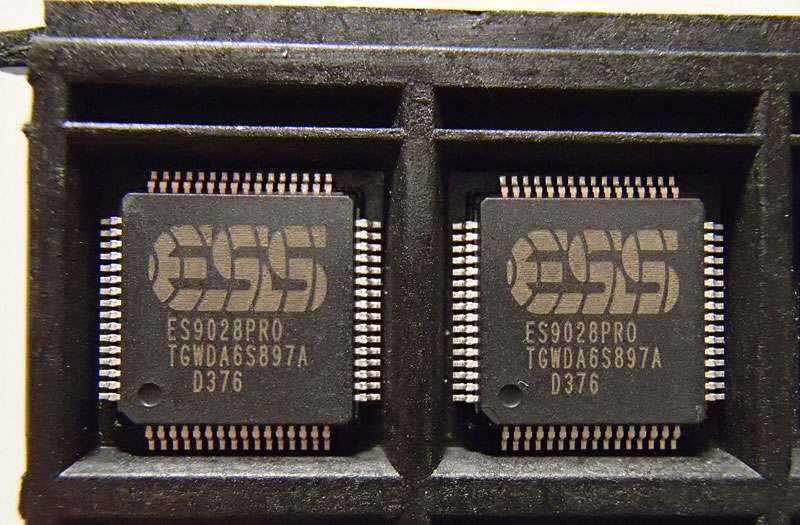
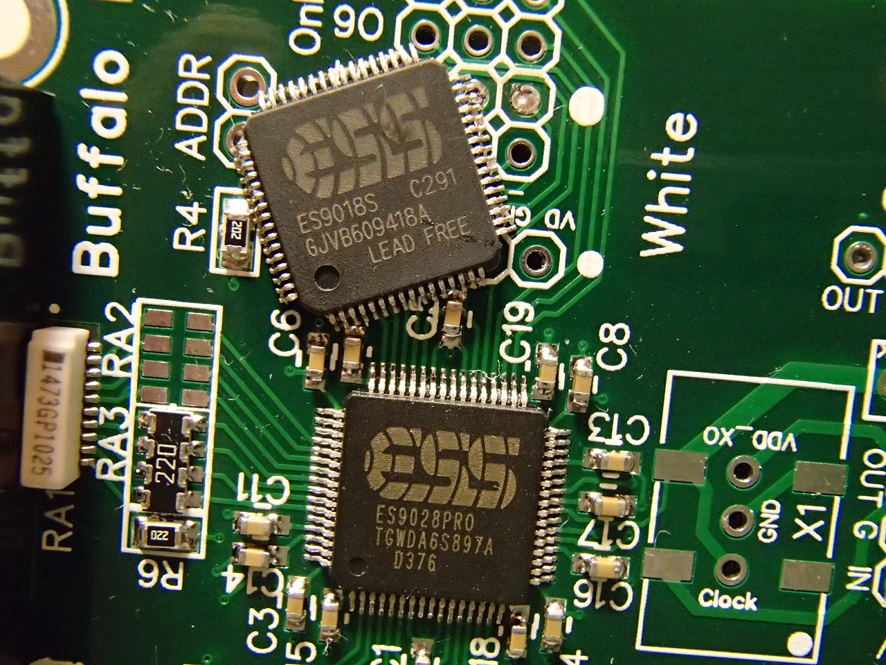
Note that not all DAC chips can operate in either of the two modes. Most widespread is the Slave mode, in fact practically all DAC chips support it. The Master mode is supported by a small percentage of DAC chips, like the PCM5xxx series by Texas Instruments or the new ESS DACs (like the ES9038Pro). Well known DAC chips that do not support Master mode include the older ESS chips (ES9018, ES9018K2M, ES9023, etc) and the Asahi Kasei DACs (AK4490, AK4495, AK4497, etc.).

The DACs

With that out of the way, lets see our contestants.

The Mamboberry LS DAC+ is a moderately priced (54.90€) ES9023 based DAC designed to run in slave mode to the RPi. It is considered one of the better sounding HAT DACs out there.

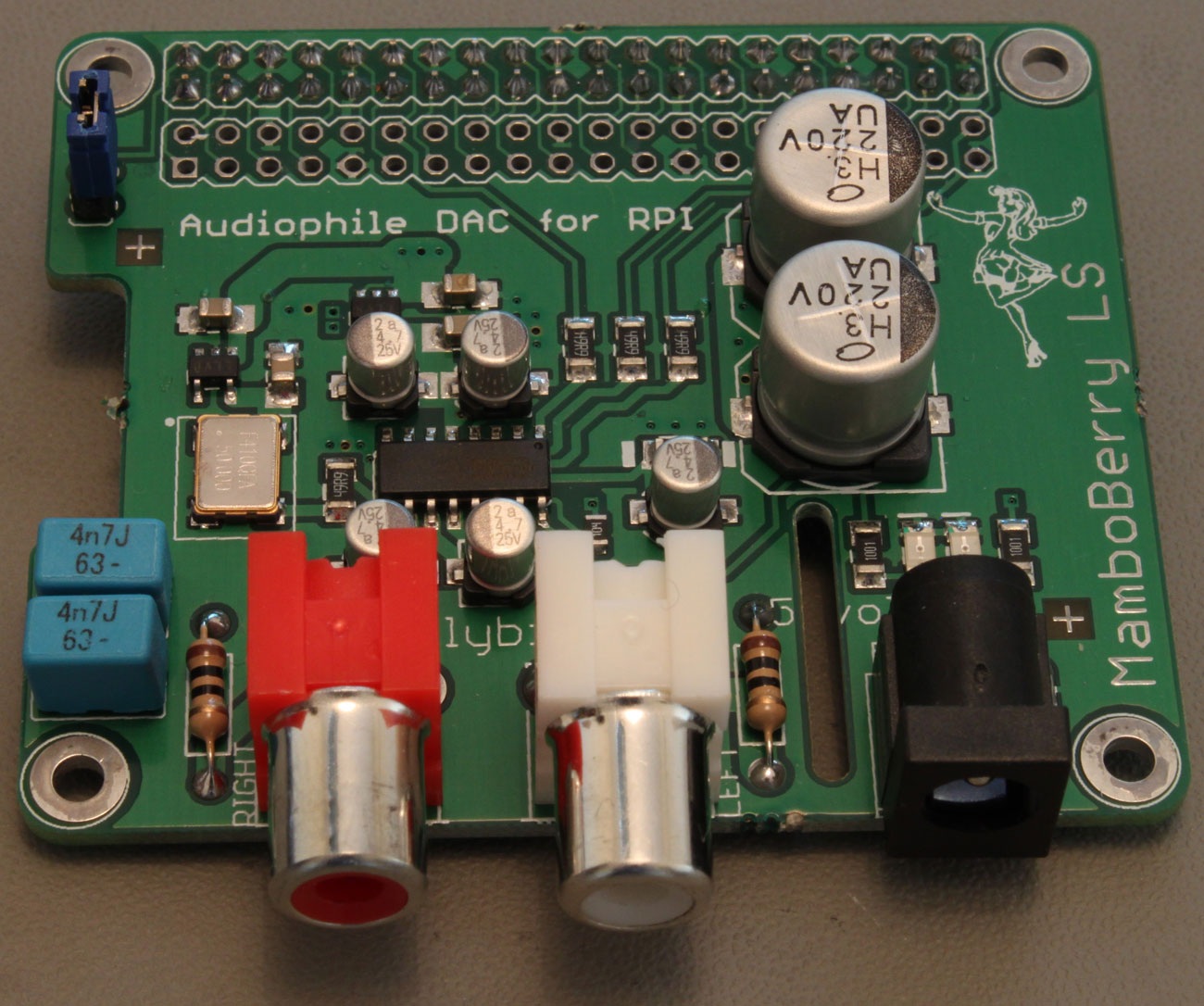
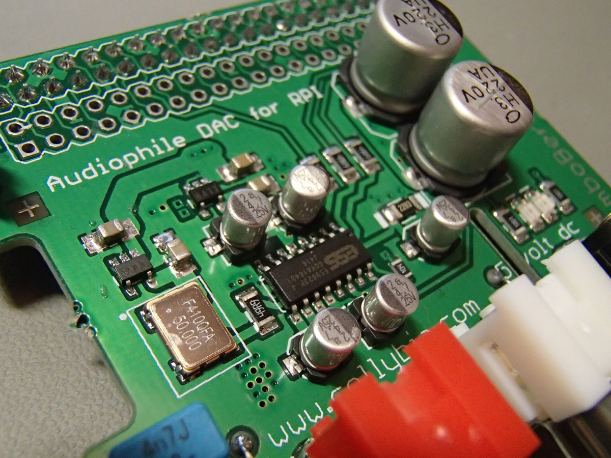
It has an on-board high quality oscillator (by Fox) running at 50MHz (this essentially means that the 9023 is running at asynchronous mode, that is it is resampling all incoming PCM signals), very good quality LDO regulators and passive components.

It may be powered either through the RPi or by an external (preferably linear) power supply. Officially the ES9023 supports sampling rates up to 192KHz but unofficially it goes up to 384KHz / 32bit. It doesn’t really require special software support on the RPi, you just set it for “generic I2S output”.

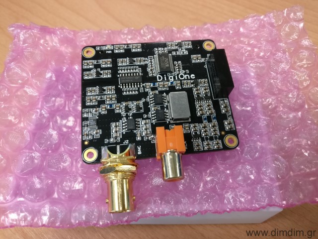
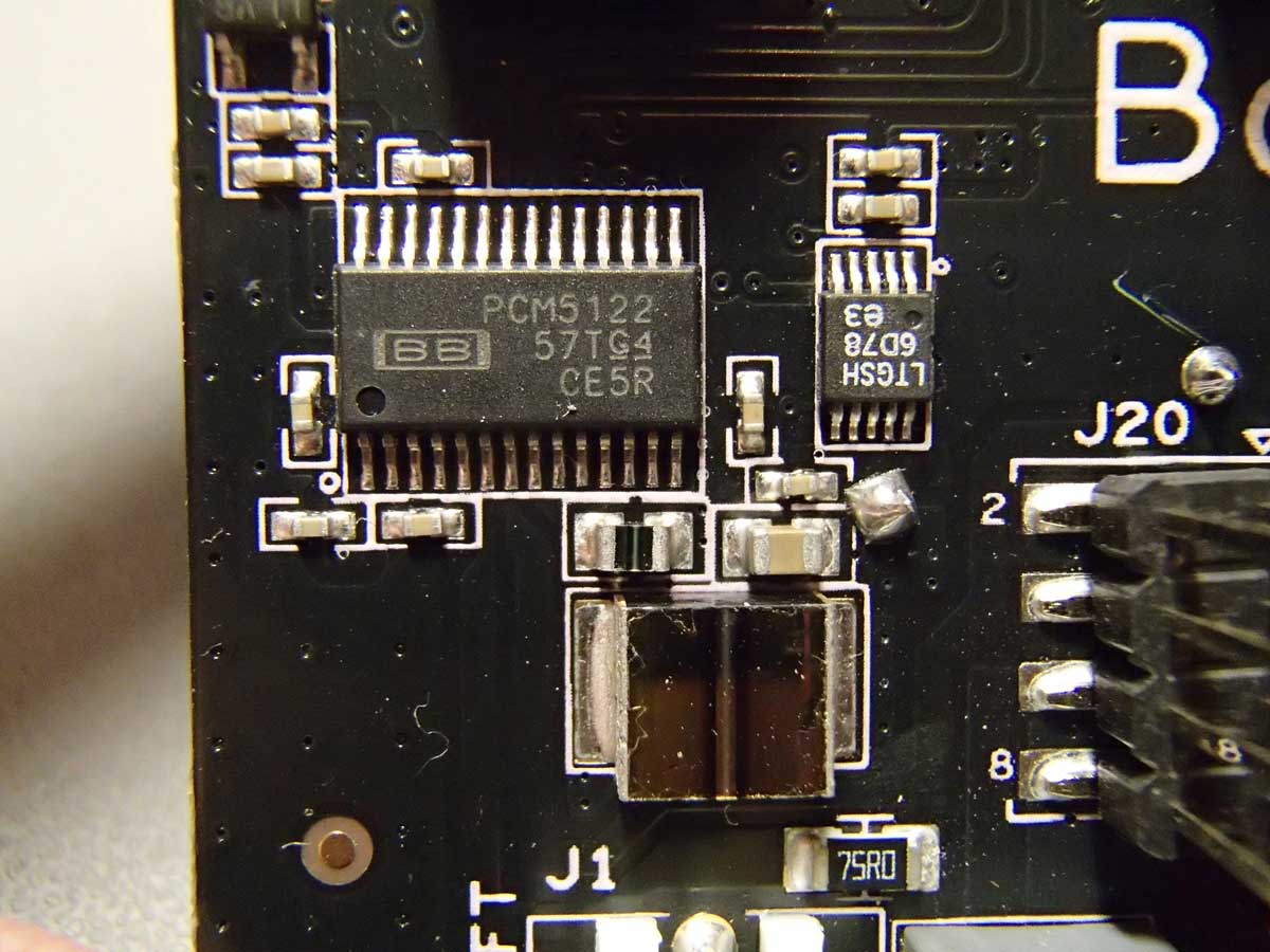
The Allo.com BOSS DAC is a somewhat pricier (~70€) master mode DAC.

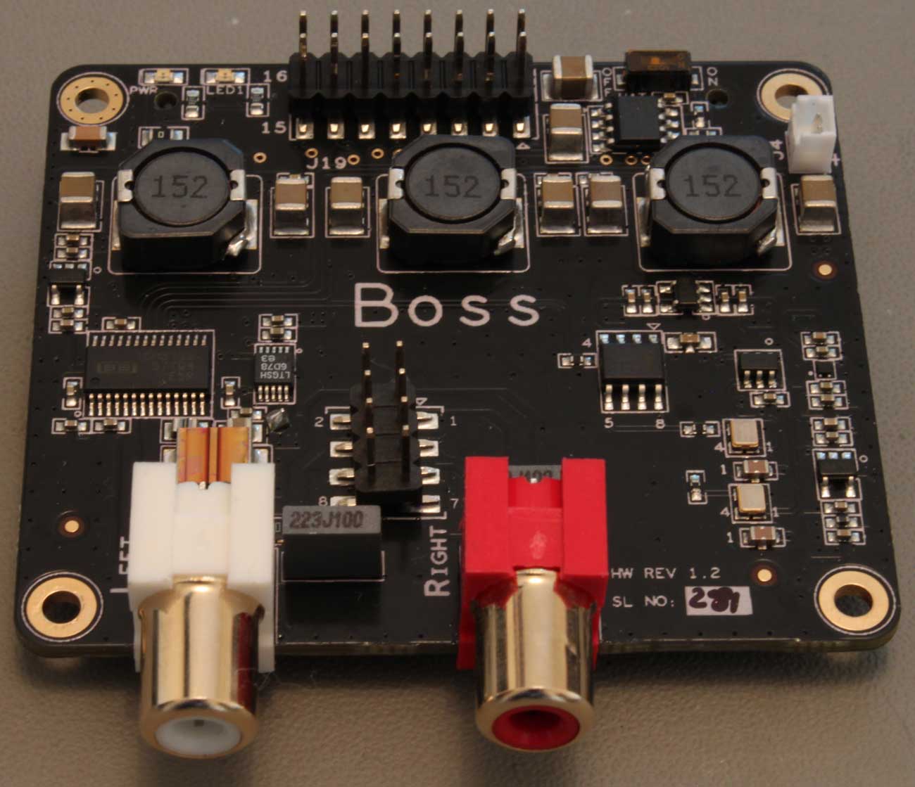
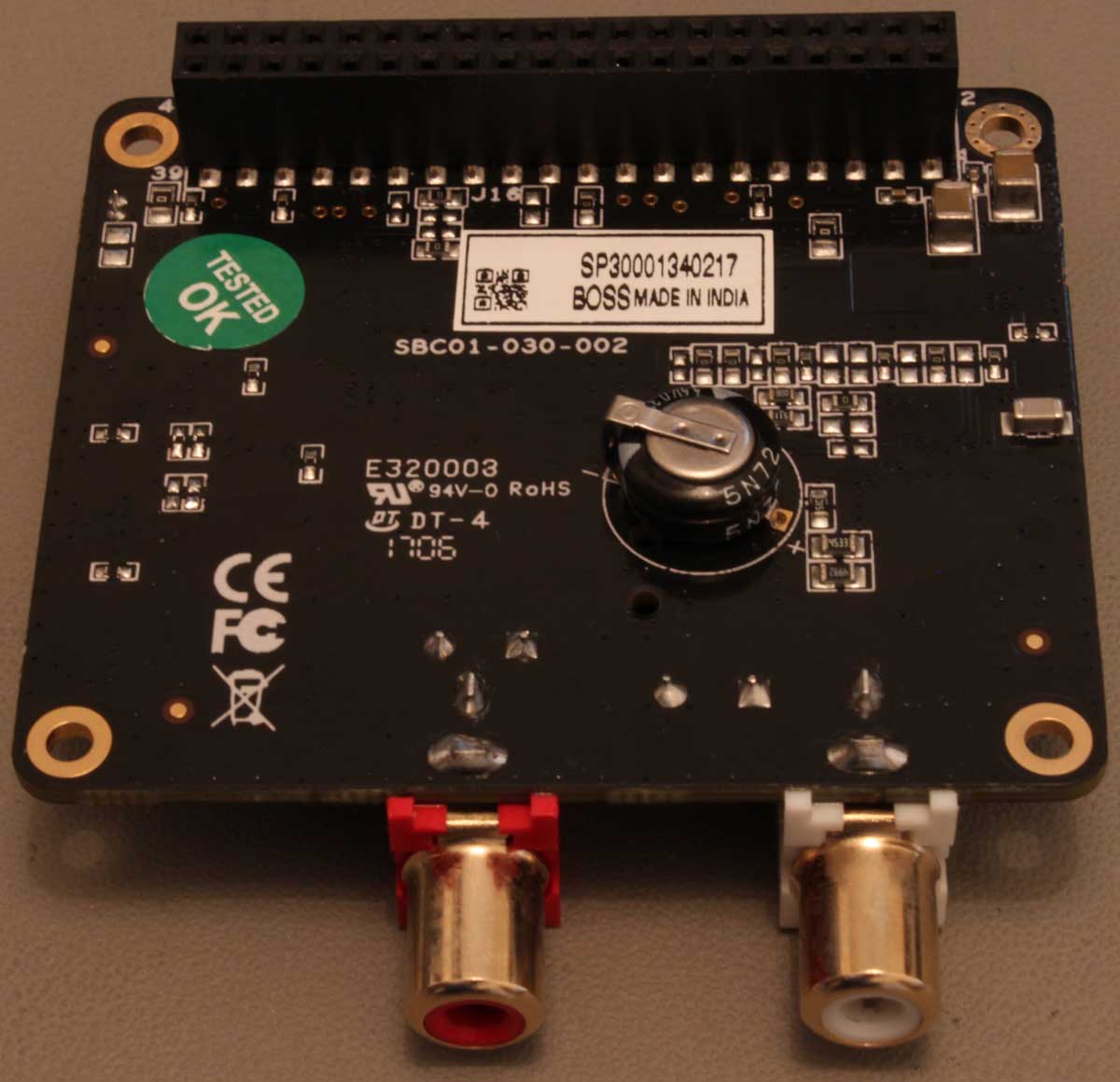
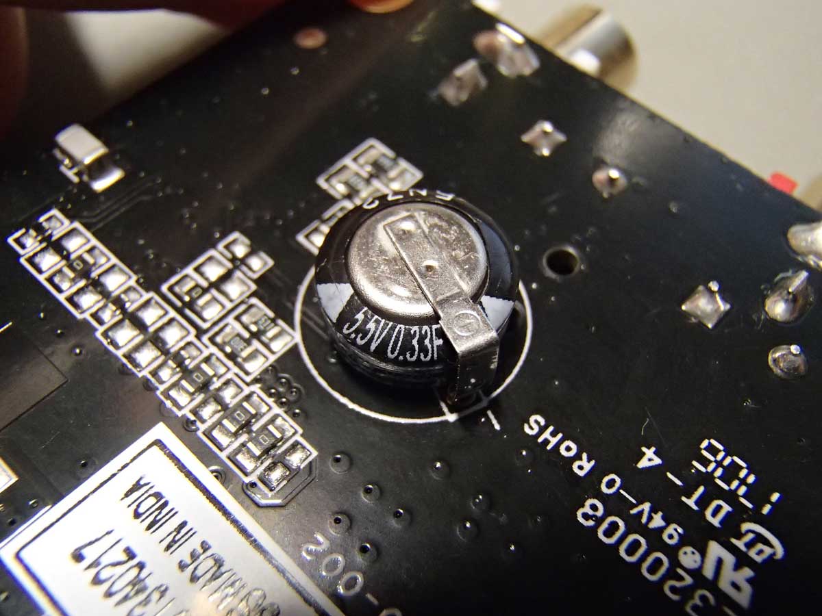
It is based on the PCM5122 DAC, powered by a top-quality LT3042 LDO regulator utilizing DC filtering by very high quality capacitors (including a 330.000uF supercapacitor!).

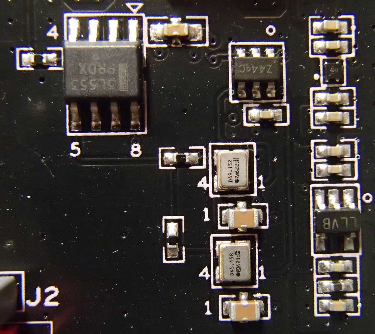
Clocking is done by a pair of NDK extremely low jitter and low phase noise oscillators (45.1584 & 49.1520 MHz), powered by their dedicated LDO regulator. Their output is buffered by an NB3L553 clock fanout buffer IC which further reduces the jitter.

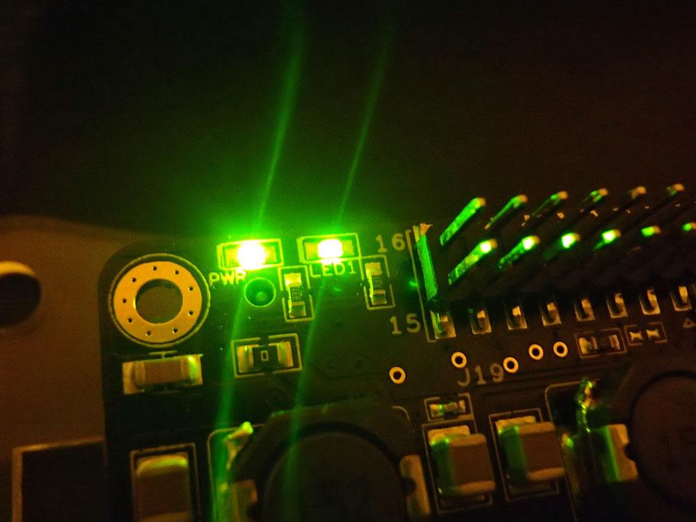
Sampling rates up to 384KHz / 32bits are officially supported. It’s powered through the RPi, but it has an “Optional 5V battery power in connector” for future use. I suspect that this connector can also be used to power the Boss, but a certain resistor will need to be removed to isolate this power from the RPi. This DAC needs a special driver, since it needs to set the RPi in slave mode and also communicate with it via I2C to set operating parameters and utilize the PCM5122’s hardware volume control. When the DAC is receiving data from the RPi, the indicator “LED1” lights up.

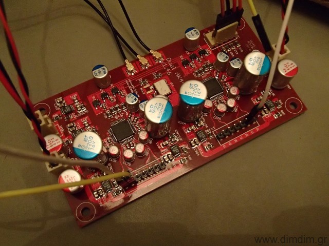
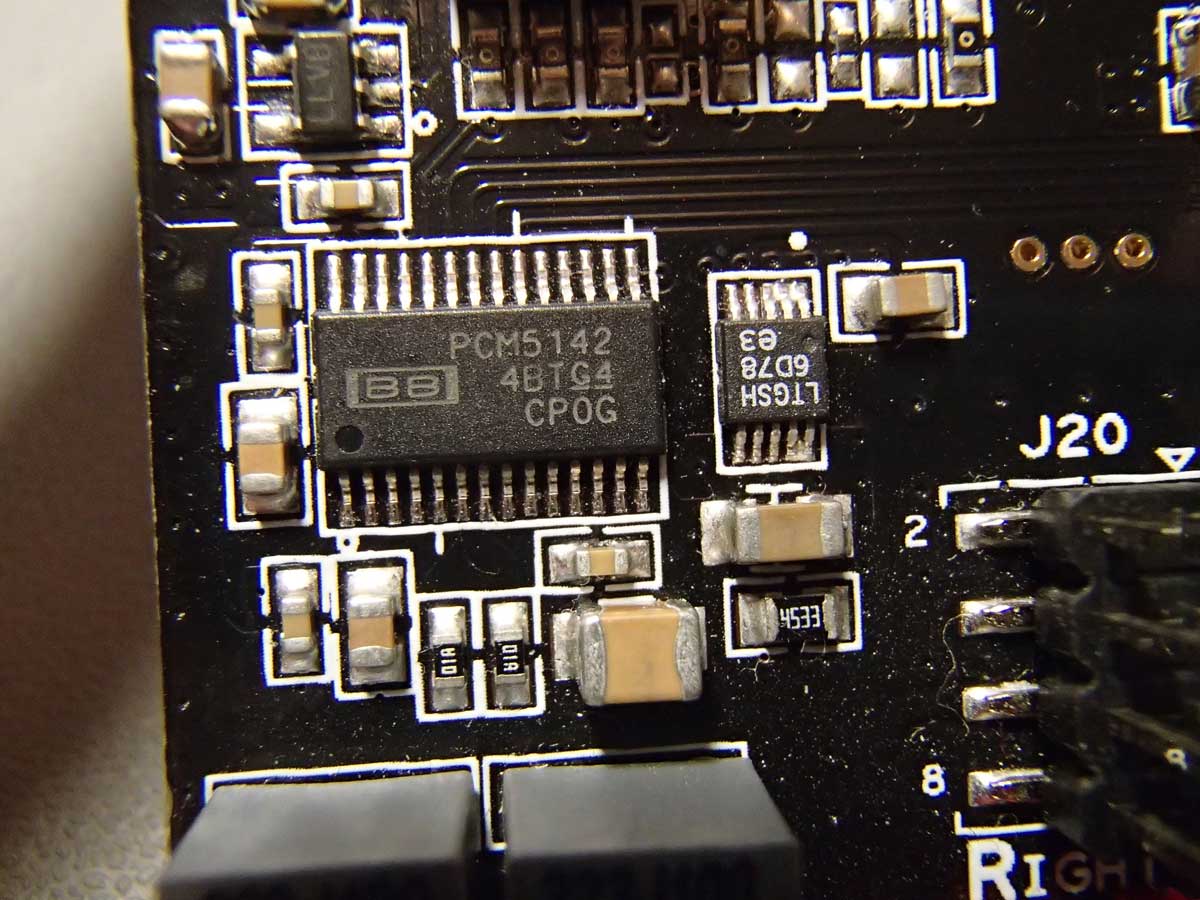
The Allo.com Piano 2.1 Hi-Fi DAC is another moderately priced (~55€) slave mode DAC, based on PCM5142 DACs. Notice the plural.

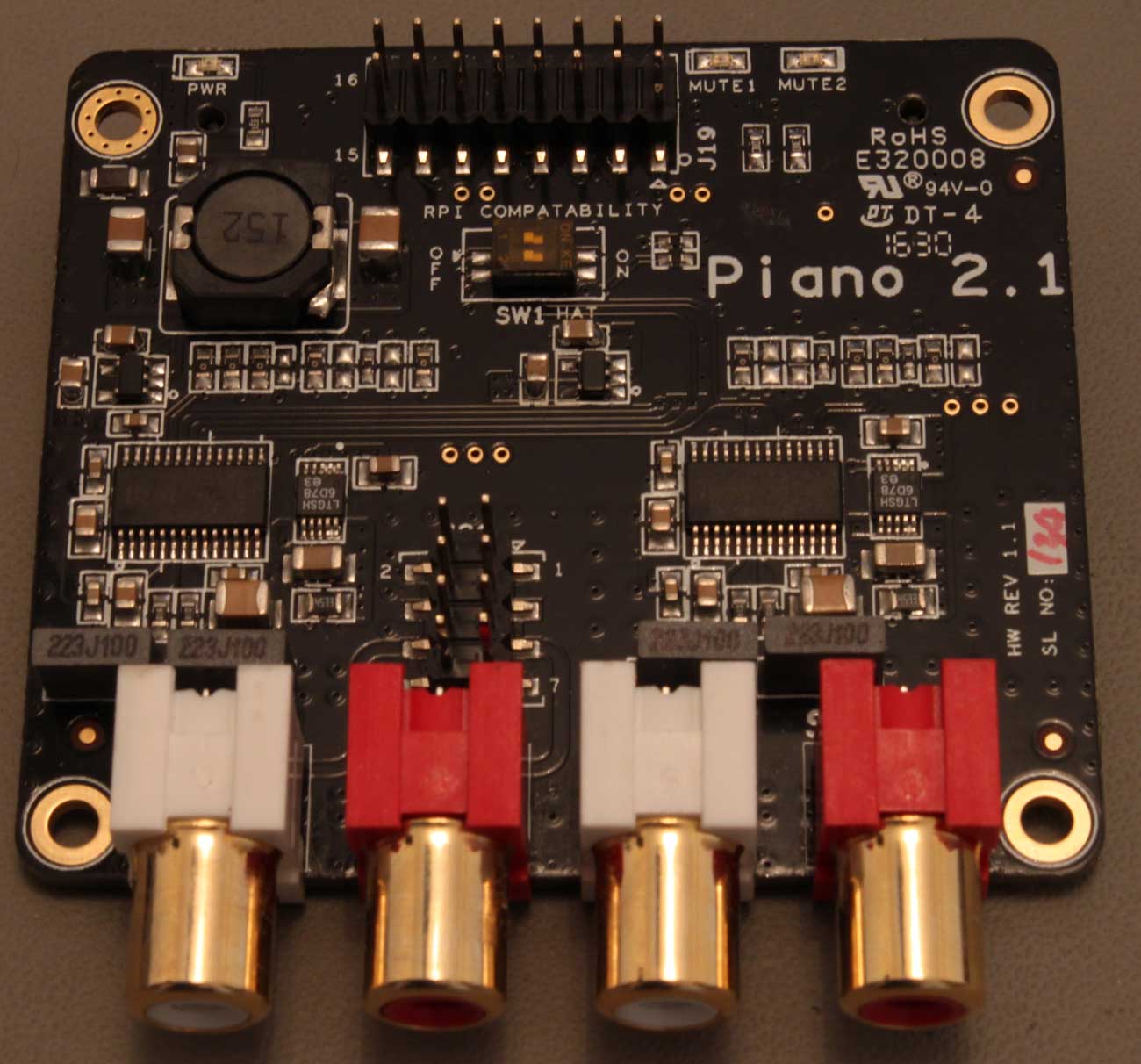
On board this HAT we have two DAC chips that output a total of 4 channels. Each of the DAC chips also contains a DSP core, capable of doing equalization, filtering or other functions. These DSPs can be configured using TI’s PurePath software, but that is not a trivial task. The distributions that include built-in support for the Piano 2.1 come with a pre-built set of filters, capable of essentially configuring the DAC in 2.1 mode so that it can be used with one or two subwoofers. The analog sections of the DAC chips are powered by two top-quality LT3042 LDO regulators.

There exists no on-board oscillator, since the DACs are running in slave mode. Sampling rates up to 384KHz / 32bits are officially supported. Power is supplied by the RPi. As you can imagine, this DAC also needs a special driver, since it needs to set up the filters in each of the DAC chips plus to utilize the PCM5142s’ hardware volume controls.

A word about audio distributions

There are many audio-oriented distributions available, such as Archphile, RoonAudio, Moode and Volumio. In order to do a fair comparison, I opted to use the same distribution for all tests. The logical choice was Volumio, since it includes proper support for all of our DAC HATs.

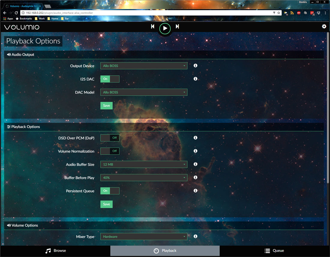
Volumio is very easy to install and is very responsive in my RPi3. No complaints whatsoever.

Testing Methodology

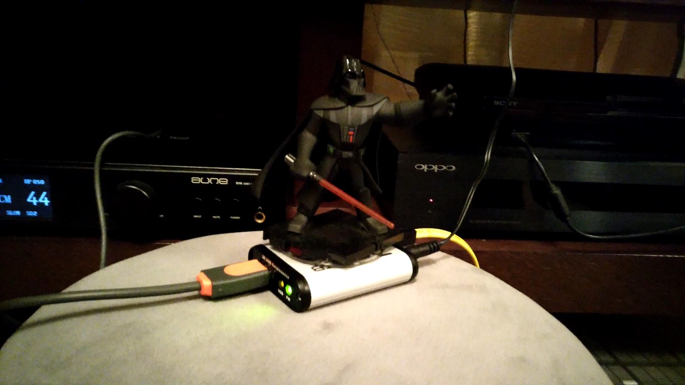
The idea was to test the DACs in their default operating mode, that is with no mods and no exotic power supplies. When testing without Kali, the RPi3 & DAC were powered by a 5V 2A SMPS I had lying around from an old tablet. It’s a pretty high quality unit, made by HP. Still, at the end of the day it’s just a wall-wart SMPS.
When testing with Kali, I powered the RPi3 with the same SMPS plus I used an 7805-based linear power supply for the Kali & DAC (jumper on Kali was removed to isolate its power from the RPi’s). Again, nothing exotic. Just a relatively low power (1A max) linear power supply.

After I had an initial listen to all of the DACs in pretty much every possible combination, like “plain DAC” or “DAC with Kali” (where applicable of course) and drawn my conclusions, I thought I would take the system “on tour” to a couple of my friends and their superior sound systems. By doing this I was getting a second and third opinion. So, friend#1’s system is a full-blown MBL installation costing upwards of six figures. His main DAC & transport’s cost is in the 20K range. Friend#2’s system is a more DIY affair, consisting of big (and I mean BIG) Magnepan speakers, diy solid state power amp (several hundred watts per channel, many of them in class A, it makes a lot more than a ding in his power bill), diy preamp, Sony XA50ES modified CD player plus (on loan from me) a Soekris DAM1021 DAC.

At friend#1’s, we used an SPL meter to equalize the volume levels between all of the DACs. We listened to 3 specific tracks. At friend#2’s, we also listened to the same 2 or 3 tracks on all of the DAC combinations but didn’t take much care of level matching. The observations of my two friends were practically the same, so I won’t distinguish between them.

The Results

We started with just the RPi with Mamboberry LS. The sound was OK, not nearly what you would call “hi-end”, but considering the DAC’s cost it was more than satisfactory.
We then moved on to the RPi with the Boss. The improvement in audio quality was more than apparent. The soundstage became better defined, the instruments more clear, the bass just.. more, but in a good way.
Next up was the Mamboberry aided by Kali. Kali did more than just fix up the I2S signal – it also provided clean power to the Mamboberry. Now the Mamboberry began to show its teeth. This combination gave a more clear result than the Boss DAC, like the music became even more life-like. The bass did not have the same authority, but overall the combination Mamboberry & Kali definitely sounded superior to the Boss.
Finally, we teamed the Piano 2.1 to the Kali. The Piano was configured in stereo mode, since there were no subwoofers present. This combination gave the best overall result, giving a more “analog”, musical result. Its sound was the most smooth of all of the combinations, while at the same time it was the most life-like. You could say that it was the least fatiguing of the bunch.

After we were done comparing the HAT DACs, we thought we should listen to our “proper” DACs, just to put things into perspective. To no surprise, both my friend#1’s DAC and my Soekris properly cleaned the floor with the HAT DACs and it’s a good thing that they did – otherwise we would have felt pretty dumb having wasted so much money on so-called “proper” DACs while we could have got the same result with these DAC HATs. Phew.

So, the end result is not really surprising. The more money you spend, the better sound you will get. No giant killers here. But regarding value-for-money, I think that the Boss DAC claims the prize.

Happy π day everyone! 😀

Ideon Audio 3R USB Renaissance

OK, so this small Greek company comes up with a USB regenerator gadget targeted towards audiophiles.

They claim that it improves audio dramatically. It uncovers lost detail, enhances dynamics, etc.

We’ve heard all that hi-end mumbo-jumbo before, right?

Problem is, this time the gadget actually works. I didn’t believe it either until yesterday, when I was invited to a friend’s house. Also invited were a couple of friends and this little guy:

It was accompanied by its designer, Vasilis of Ideon Audio. Mind you, this is the same Vasilis that is behind the Mamboberry DACs.
I’ve known Vasilis for the better part of 10 years now. We have exchanged some pretty sharp remarks over the years, in regards to our shared hobby, but this time I must admit that he’s really on to something.

The 3R contains a TI chip with a low jitter clock and a bunch of LDOs. It is powered by an SMPS wall-wart (rumor has it that it works even better powered by a linear power supply).
What happens is that the 3R is detected by the PC as a USB device which essentially passes-through the DAC that it is connected to. It works like a USB hub – it’s an active device but it needs no drivers.
It works its magic by regenerating the USB signal using its own low jitter clock and low noise LDO regulators.

The end result is that the DAC manages to literally extract more detail from the music stream, be it from a PC or a Mac based transfort. It doesn’t matter what your DAC is – it will make a positive difference. We tested it with a Buffalo III dac (Amanero as receiver with no isolation) and with an Aune S16 (XMOS receiver, isolation, and FPGA doing FIFO and reclocking). In all cases, introducing the 3R into the chain made for better bass definition, more resolution, and better sound stage.

This is some upsetting stuff. This made me feel the same way I felt a few weeks back when I was auditioning Salas’ system and I could hear audible differences when we changed Foobar’s buffer length from 400ms to 1000ms. This shouldn’t happen, but it does.

I don’t know.. Perhaps this is a sign that I should switch to another hobby.

In conclusion, here is a picture of Darth Vader on the 3R:

If you have a half-decent USB dac and you’re serious about audio reproduction (a.k.a. you’ve already invested in a good sound system) you should get one. Not Darth Vader, the 3R.

STM32 Microcontrollers & Arduino

I love Arduinos as much as the next (nerdy) guy, but let’s face it, they are no powerhouses (DUE and ZERO excluded, but they discontinued the former.. go figure..).

The Atmel AVR series is 8-bit and its clock is ridiculously slow by today’s standards.

Sure, you can get it to do some things with impressive speed if you are willing to do some low-level programming but I myself do this as a hobby and thus don’t really want to deal with assembly-level code.

If only there was a fast and cheap microcontroller that was easy to program..

Enter the ST STM32F103C family of microcontrollers.

These little wonders are:

  • Friggin’ fast. 32bit ARM architecture running at 72MHz.
  • Very well equipped in the I/O department.. 2 x UARTs, 2 x SPI busses, 2 x I2C ports, etc.
  • Easy to program using the familiar Arduino IDE, thanks to the work done by the wonderful people at www.stm32duino.com
  • Dirt cheap. You can get an Arduino Nano – sized board for less than 3€ shipped.

It’s pretty easy to get started using these microcontrollers. All you have to do is buy a tiny board from Ebay. You will also need a USB to Serial adapter that works with 3.3V voltage levels (you probably already have one of those lying around already..).

These tiny boards are known as “Blue Pills” or “Red Pills”, according to the colour of the PCB. There are other variations as well, but the red and blue variants are the most commonplace. They have relatively minor differences.

This is the pinout for either one of them:

To get started, you have to connect your USB to serial port adapter to the STM32’s RX1, TX1 and GND pins. RX from USB adapter goes to TX1 (PA9 pin) and TX goes to RX1 (PA10 pin).

To make the Arduino IDE compatible with these boards, you have to download the necessary files from here: https://github.com/rogerclarkmelbourne/Arduino_STM32

You then unzip the libary to C:\users\\Documents\Arduino\hardware\ or C:\Program Files (x86)\Arduino\hardware\

At the time of this posting, IDE 1.8.0 (latest available edition) is properly supported. You will also need to install support for the Arduino DUE or ZERO from the Boards Manager, otherwise you will get a “/bin/arm-none-eabi-g++: no such file or directory” error.

If everything went fine, you should see in your IDE a number of new available boards:

You select “Generic STM32F103C series”, the 128k variant, 72MHz speed, and Serial upload method:

You are now ready to try your first code upload.

The classic test is the Blink sketch:


// the setup function runs once when you press reset or power the board
void setup() {
// initialize digital pin PC13 as an output.
pinMode(PC13, OUTPUT);
}

// the loop function runs over and over again forever
void loop() {
digitalWrite(PC13, HIGH); // turn the LED on (HIGH is the voltage level)
delay(1000); // wait for a second
digitalWrite(PC13, LOW); // turn the LED off by making the voltage LOW
delay(1000); // wait for a second
}

In case of the STM32 uCs, the only necessary modification is changing the pin number of the LED to one compatible with the Blue (or Red) Pill (PC13).

Pin numbers for this family of uCs are not just numbers like they are for the Arduino boards (like 1,2,3….,A1,A2,…) but are named as they are described in the uC’s datasheet (PC13, PC14, etc.).

The procedure for uploading code is a little different than the one for the Arduinos. The STM32s come with 2 built-in bootloaders. One of them boots from system memory and the other from program memory. These different bootloaders are selected by changing the position of the BOOT0 jumper. You set it to 1 to boot from system memory or to 0 to boot from program memory.

To upload our code, we do the following:

  1. Set ‘BOOT0‘ to 1. This way we will boot from system memory which contains a UART to flash uploader.
  2. Press the RESET button.
  3. In the Arduino IDE, choose ‘Upload‘. On the board, the blue LED will start to flash.

After the upload is completed, our sketch will start. We should see the blinking LED.

If we want our uploaded sketch to boot automatically after the next power-on/reset, we need to set ‘BOOT0‘ back to 0 (so that on next powerup we will boot from program memory).

That’s pretty much it. Your next step should be to go to STM32duino’s forum and check out the libraries that have already been ported to the STM32duino environment.

Troubleshooting

If your sketch fails to compile, giving you a “/bin/arm-none-eabi-g++: no such file or directory” error, make sure that you have installed support for the Arduino DUE or ZERO from the Boards Manager.

If you get an error on the IDE that it “Failed to erase memory”, that means that your STM32 chip is locked. No worries, all you have to do is go here and get ST’s Flash Loader Demonstrator utility. It will unlock the chip with minimum effort. Be sure to run it as Administrator in Windows.

st_flash_loader_demonstrator_1

st_flash_loader_demonstrator_2

Blue Pill reference: http://wiki.stm32duino.com/index.php?title=Blue_Pill