Following up on Part 1, it’s time to talk about the “brains of the operation”. Bare with me, this is going to be a rather long read.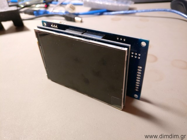 Hardware selection
The DAC needed to be controlled by a microcontroller so I looked into my options. I wanted something that would:
- Be easy to program, so the Arduino IDE was a must.
- Be able to drive a TFT.
- Have enough storage capacity to store enough code & fonts for the TFT.
- Be readily available.
- Be relatively low cost, since it would have no influence on the dac’s SQ.
- Be easy to build / integrate into a new design, even by a novice.
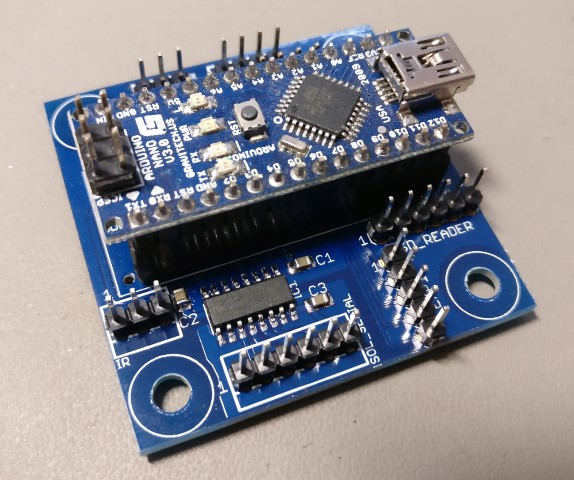
After some consideration, I decided to use an STM32F103 ready-made module. It would plug in to a “mainboard” of my design, along with the chosen TFT. It would be fast enough, have enough flash & ram, be easy to integrate and develop for and it would cost next to nothing.
Next up was the TFT. I’d seen on Ebay an interesting one that was relatively big, high resolution and inexpensive. It was this one:
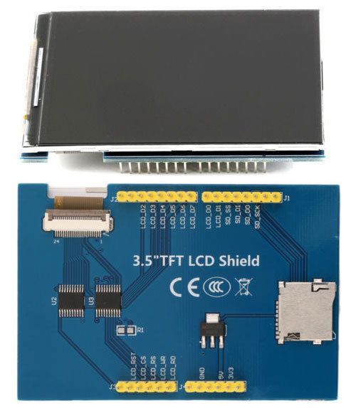 It can be found on Ebay by searching for “3.5 tft uno 320 x 480”. Expect to pay 6-8€ inc. shipping.
After some searching I found a suitable library that (after some slight tinkering) would allow my tiny STM32 to drive it properly. (Note: do not download the library from this link. I will provide a customized version of the library together with my code).
I found a ready-made library for configuring the Si570 and modified it to run on my STM32, using one of its hardware I2C ports. I will also include this library in my code. To complete the recipe I also found working rotary encoder and IR receiver libraries.
The code
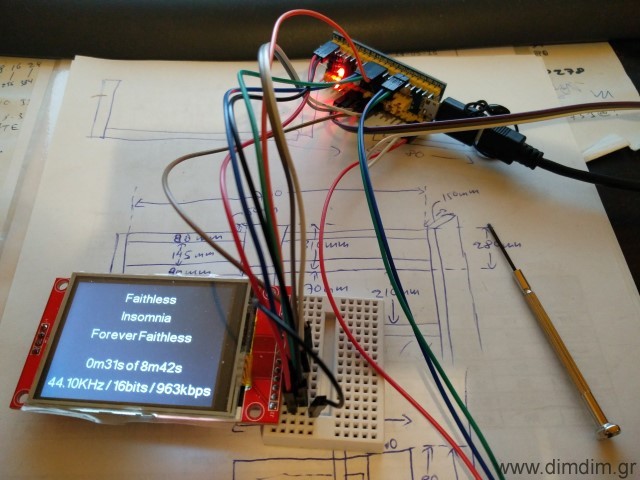
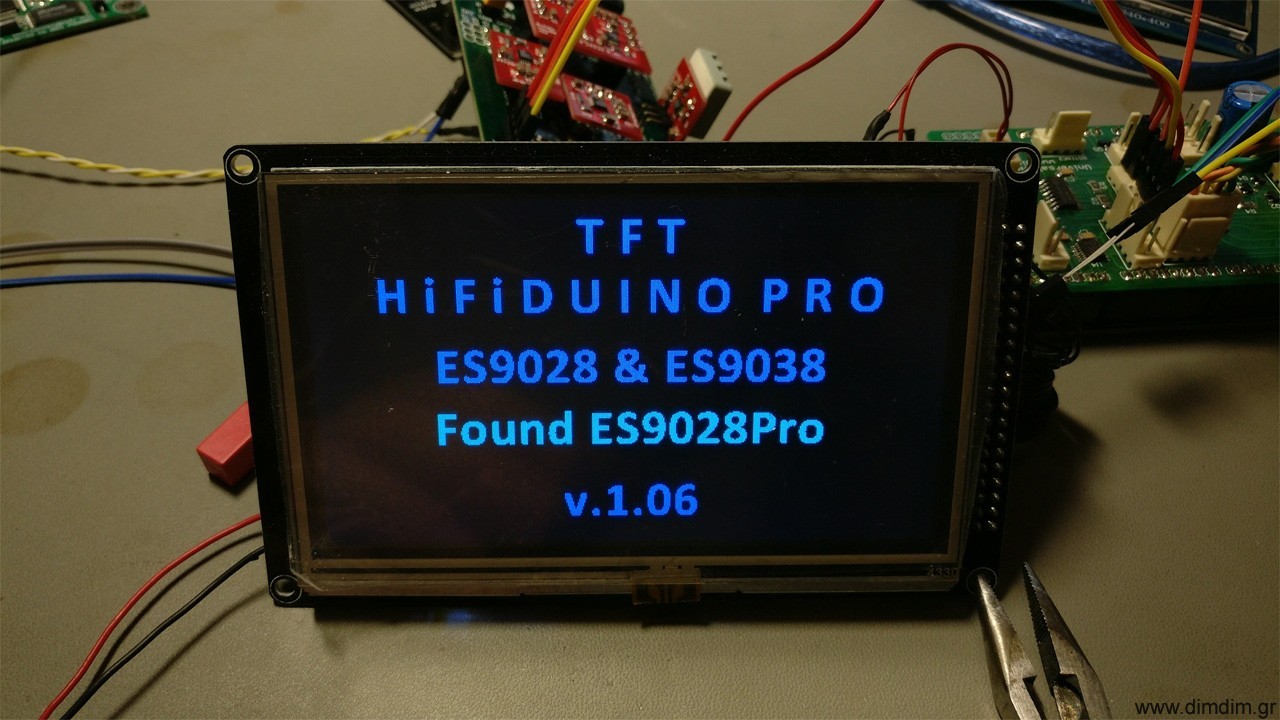
Next up was the prototyping work. I adapted my TFT HiFiDuino Pro code to run on the STM32 & TFT combo, with support for AK4490 dual mono operation. The end result had this feature list:
- Support for either Dual Mono or single chip setups.
- Support for the Amanero Combo384 USB to I2S module (must be set up as slave with MCLK/2 and F0,1,2,3 enabled).
- Control with one rotary encoder with push-to-select functionality.
- IR Remote support.
- Support for software volume control, from -99dB to 0dB
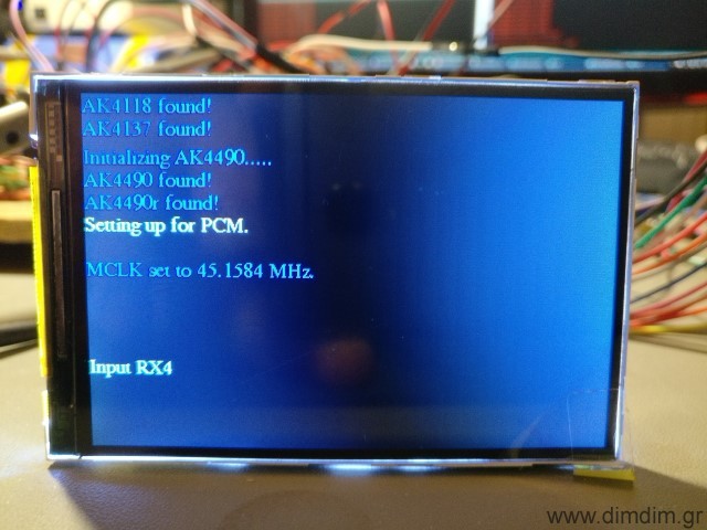
- Display incoming signal sampling rate and type, determined by “reading” the relevant I/O pins of the USB to I2S board.
- Display and control of the AK4490’s digital filter.
- Selection of the proper MCLK frequency according to incoming SR and type and programming of the Si570 accordingly.
- Control of “DSD Direct” function of the AK4490s.
- Control of the DSD Filter’s Frequency (50KHz or 150KHz).
- Control of the Sound Mode of the AK4490.
- Choice of either inverted or normal analog output for the AK4490s.
- Choice of two sets of MCLK frequencies, either 22/24MHz or 45/49MHz.
- Remote power on/off functionality (or always on – configurable in the code).
Software Requirements:
- TFT Library (included in ZIP, derived from this one: http://stm32duino.com/viewtopic.php?f=9&t=1751). I have also available a modified library that will work with 3.5″ TFTs using the ILI9486 controller, such as the ones offered on Ebay lately. Download here: Adafruit ILI9486 8bit STM library (261096 downloads )
- Rotary Encoder library: https://github.com/mathertel/RotaryEncoder
- Adafruit MCP23008 library (included in ZIP, derived from this one: https://github.com/adafruit/Adafruit-MCP23008-library)
- Adafruit GFX library: https://github.com/adafruit/Adafruit-GFX-Library
- Si570 library (modified to utilize the STM32’s hardware I2C pins, included in ZIP, derived from this one: https://github.com/afarhan/radiono/tree/master/radiono)
- IR remote library, compatible with the SMT32 (modified version of this library, sourced from here, also included in the ZIP)
In the download I am including the modified versions of the libraries (as mentioned above) as well as the necessary font files. Be sure to extract the contents of “Libraries (place in Libraries folder)” to your Arduino IDE’s “libraries” folder.
Download it here: aKduino v2 (152444 downloads )
Here is the revision history:
v1.72 24/12/2017:
- Minor changes to make compatible with current stm32duino core (changed HardWire.h to Wire.h and other minor stuff).
- First public release as part of completed dual mono DAC project.
v1.66 10/10/2017:
- Minor volume bugfix.
- SuperSlow filter still problematic.
- Enabled DAC synchronization feature (experimental..).
v1.64 30/09/2017:
- Bugfixes.
v1.60 20/09/2017:
- Added support of rotary encoder and IR remote control.
- 3.5″ TFT support.
v1.50 07/01/2017:
- Added support of rotary encoder for volume control.
- Bugfixes related to DSD.
v1.41 06/01/2017:
- Added support for dual mono mode.
v1.36 03/01/2017:
- Added very basic TFT support.
v1.35 20/12/2016:
- Code cleanup for first public release.
v1.33 19/12/2016:
- Added full control of sound parameters through serial port.
v1.27 18/12/2016:
- First functional version.
- Automatic switching between PCM and DSD by monitoring DSDPIN.
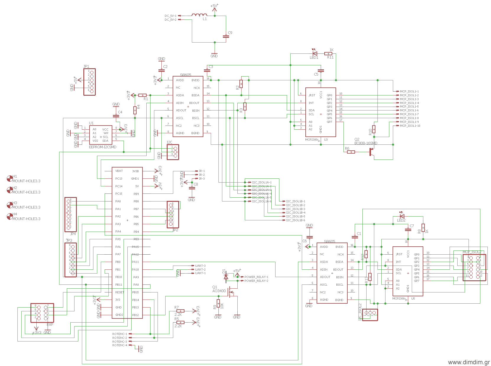
The “motherboard”
After I was certain that everything related to the software was working the way it should, I designed a “motherboard” that would take care of the following:
- Accept the STM32F106 board.
- Accept the 3.5″ TFT.
- Accommodate an 24LC256 EEPROM chip, used to store the DAC’s configurable settings.
- Accommodate two sets of I2C signal isolators and I/O expanders.
- Include headers for the encoder, IR receiver, power relay, non-isolated and isolated I2C communication, unused uC pins, etc.
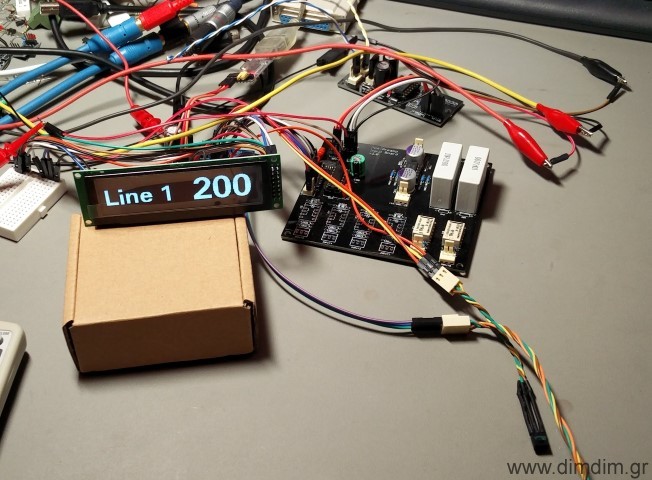
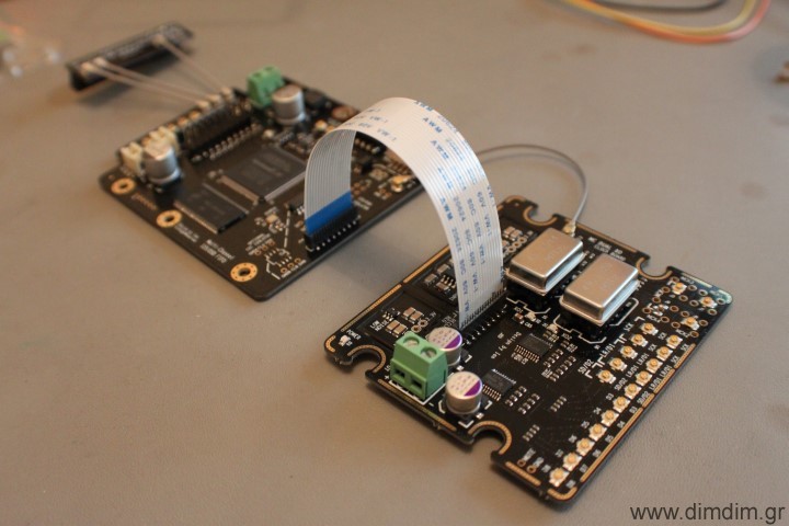
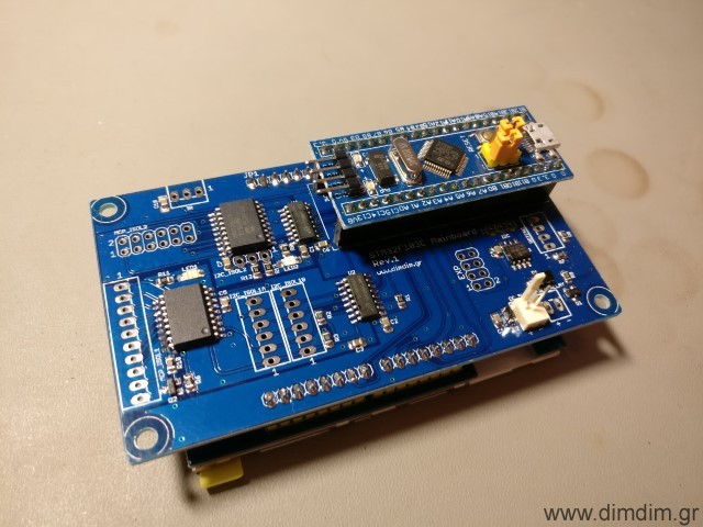
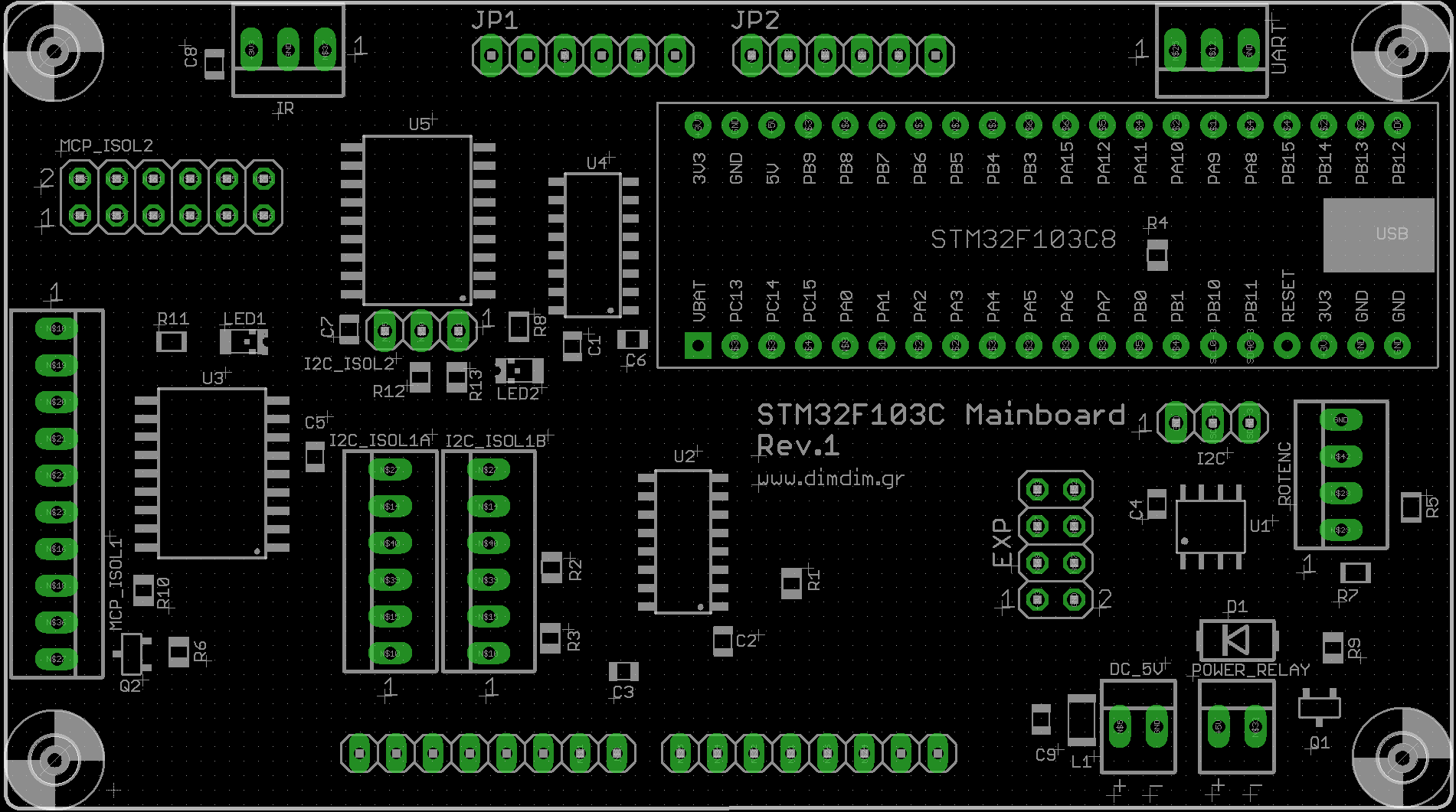
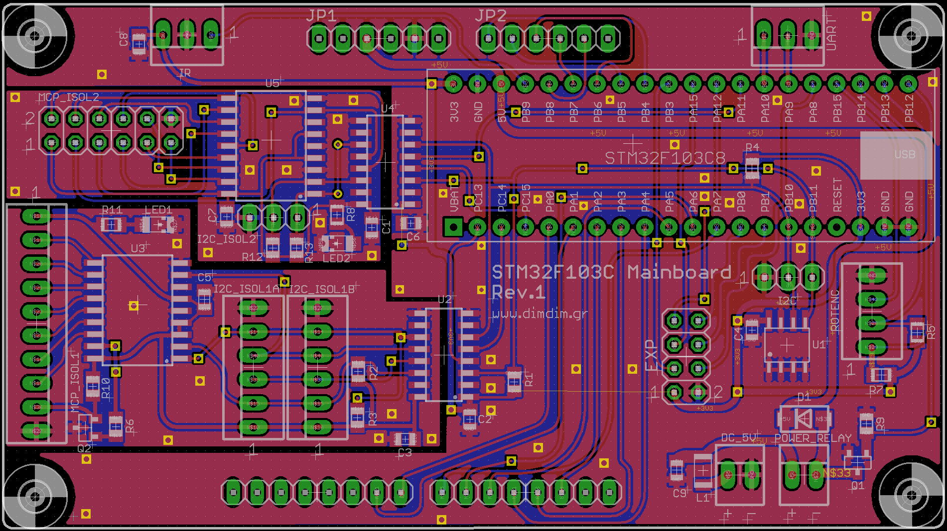
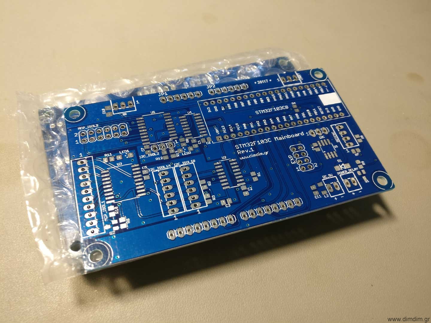
This is what I ended up with:
 Basic Hardware Requirements:
- STM32F106 module (a.k.a. “blue pill”, search Ebay for “stm32f106c8t6 board”)
- 3.5″ TFT with resolution of 320 x 480 (Search Ebay for “3.5 tft uno 320 x 480”)
- 24LC256 EEPROM chip
- I2C Isolator ICs, I/O expanders, passive components, etc (see BoM)
- Rotary Encoder
- IR Receiver
- Compatible IR remote control (Apple Remote or other – in any case you must edit the code and input the proper IR codes for your remote, see below)
How do I make it work?
Power
You have to supply the board with 5VDC at ~300mA through header DC_5V.
[table “” not found /]
Basic connectivity
Serial port:
[table “” not found /]
Rotary encoder:
[table “” not found /]
IR control:
[table “” not found /]
If you will be controlling a power on/off relay, you can use the POWER_RELAY header:
[table “” not found /]
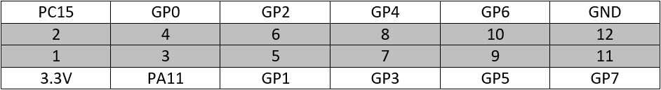
Expansion header:
[table “” not found /]
I2C header (non-isolated):
[table “” not found /]
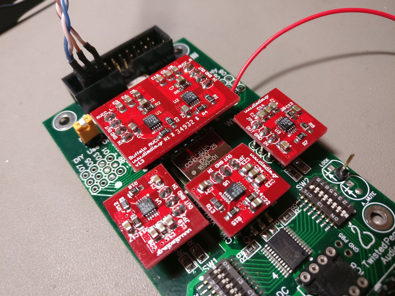
Isolated I2C ports
The board has provisions for two separately isolated I2C ports, complete with I/O expanders on their isolated sides. The idea is to connect the DAC board to one of the isolated ports (I2C_ISOL1 & MCP_ISOL1) and your USB-to-I2S board to the other isolated port (usually MCP_ISOL2)
[table “” not found /]
[table “” not found /]
[table “” not found /]
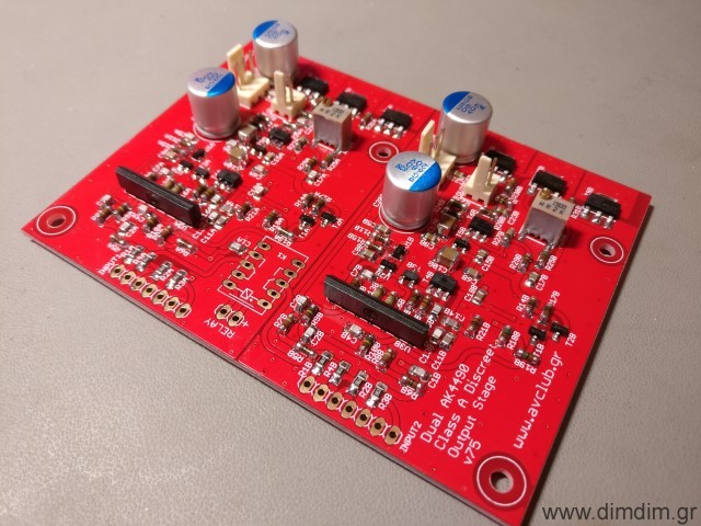
 That’s it for Part 2. Stay tuned for Part 3: The output stage.