TFT HiFiDUINO Pro update..

I finally managed to find the time to actually integrate my upgraded Buffalo III board into my Buffalo DAC.

In the process I discovered and took care of a number of bugs in my TFT HiFiDUINO Pro code.

The most serious bug was one that failed to properly initialize a new (blank) 24LC256 EEPROM chip. That effectively caused the code to crash.

Here is the change log:

v1.08 15/10/2017:

  • Fixed EEPROM init bug
  • Fixed DPLL settings bug & default DPLL settings for USB 2
  • Added alternative way of controlling Solid State Sidecar (via Pin A1)
  • Changed input names & icons to match my Buffalo III
  • Other minor bug fixes
  • Inverted power-on signal to make fully compatible with “TFT HiFiDuino” code
  • Inverted rotation of encoder to make fully compatible with “TFT HiFiDuino” code

v1.06 23/07/2017:

  • Initial release.

The new version of the code can be found at the project’s page.

Yes, I put an ES9028Pro on my Buffalo III

A few years back I was hit by Murphy and I was hit hard.

It was the time when you had to be very patient and even somewhat lucky if you wanted to buy a Buffalo DAC. You had to wait for the boards to go on sale and then be quicker than the other (equally “DAC hungry”) DIYers for the privilege of owning one.

I had just gone through all of that trouble and had managed to acquire a brand new Buffalo III board. I remember it like it was yesterday, even though it’s already been more than 5 years. I had it connected to my bench top power supply and was just doing a dry-run, I hadn’t even built the IVY-III yet, looking to see that everything was working as it should, when all of a sudden the lights on the Tridents all went very bright for half a second and then the magic smoke escaped. My power supply’s regulator IC had chosen the worst possible time to kick the bucket. Cost of repairing the power supply: ~1€. Cost of getting a new B3: ~400€ plus another 2 months of waiting.

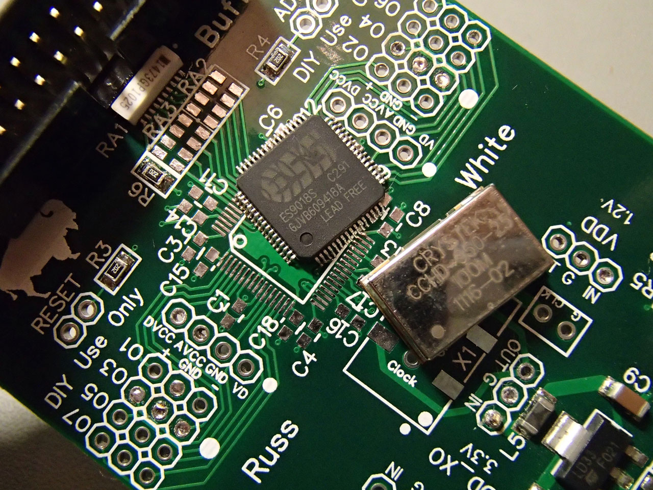
An autopsy of the damaged board confirmed my suspicions: Almost every active component on the board was gone. Besides the Tridents and the AVCC module, the ES9018S and the Crystek clock were toast. The only components that survived were the ones behind the 3.3V regulator, which proved to be resilient enough to withstand the ~35 volts that were fed to it. So the cost of repair would be prohibitive, especially considering that I couldn’t find anyone that would sell a single ES9018S chip. So the bad board went into a cardboard box and lay there for close to 5 years.

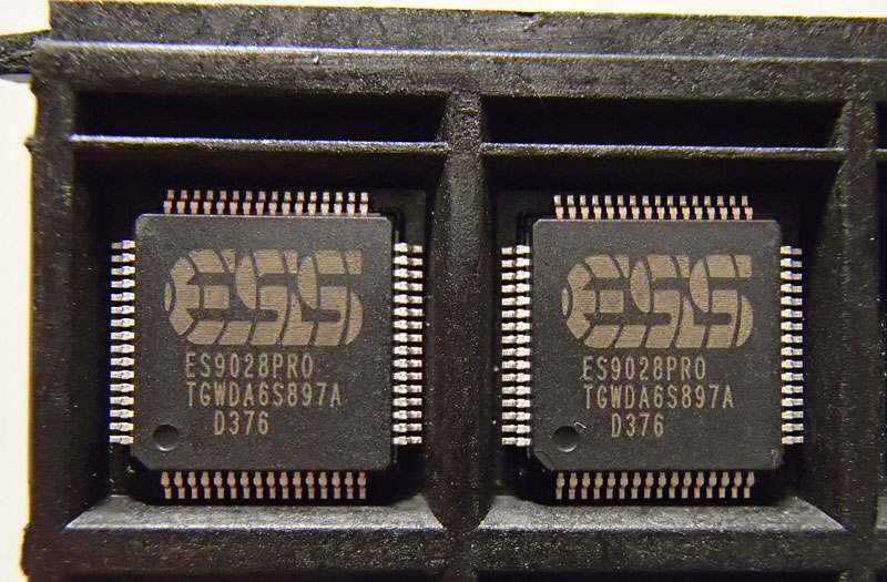
Fast forward to 2016. ESS announces the successors to the ES9018S, the ES9028Pro & ES9038Pro chips.

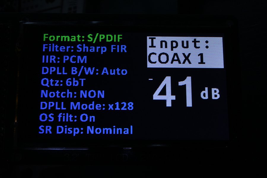
These chips have a brand new digital core, much improved from the ES9018. There are new digital filters, a new DPLL system, new THD compensation features, a new gain compensation function, etc.
The ES9028Pro is supposed to be an ES9018S with an updated digital core, while the ES9038Pro is supposed to be an ES9028Pro with 4 times the output stages, resulting in an extreme output current capability. This very high current would be the reason why its DNR and THD+N performance would be off-the-charts. But it also meant that all of the existing I/V stages that were designed for the ES9018 would not work for the ES9038Pro. As of this writing, neither Twisted Pear Audio or Acko have on offering proper I/V analog stages.

I made this little table to give you a better idea of the differences between the old and new chips:

[table “” not found /]

* up to 13
** most likely an error in the datasheet

This info comes from the official brochures that are available on-line, with some additional info from the NDA-protected “full” datasheets. ESS, if you are reading this (and you probably are), there really is no point in trying to keep these datasheets secret. If someone like me (with my non-existant connections) can find them, so can your competitors. Plus I can’t really say that I found any content in your datasheets that would warrant such extreme measures. But I digress.

So, upon inspection of the datasheets the first thing one notices is that both new chips are pin to pin compatible with the ES9018S. That was just too convenient for me and my bad Buffalo board. Good job ESS, I really appreciated that. 🙂 🙂

On the software side, things were very different to the ES9018S. The number of registers had more than doubled (48 registers in the ES9018 versus 115 in the ES9028/38) plus their arrangement was totally different, so I would need to do a total rewrite of the code to support it. Good. More fun to be had. 😀

So now a lightbulb had lit up in my head. I didn’t have much to lose – I already had the board, I could hook up temporary power supplies and a temporary clock so all I had to buy was the actual chip. Considering that I would like to be able to use my existing analog stage, I chose to go with the ES9028Pro. I got on Ebay and ordered a couple (a friend had also decided to bite the proverbial bullet and do the same “mod” to his Buffalo).

Next up was power requirements. The required voltages are the same but the required current has doubled or even tripled, depending on which chip we are talking about. That could be a problem for the AVCC module and Tridents of the Buffalo 3. I needed to do some reading-up on the AVCC & Trident modules. It turns out that the Trident modules are capable of supplying up to 100mA of power (with the proper CCS resistors) so in theory they could be made to work. But my (burnt) Tridents were v1.1, meaning that they were not exactly famous for their robust-ness. Asking them to work near their thermal limits would be looking for trouble. Plus, while researching the Tridents I learned of their latest version, the Trident SR. These now use ultra low noise LDOs (ADM715x) and are rumoured to sound even better than their older shunt types. These days my ultra low noise LDO of choice is the LT3042 so I drew up a set of PCBs that would be a drop-in replacement for the Tridents & AVCC and made an order to a well-known Far East board house.

While waiting for the chips to arrive I had put together some Arduino code that would initialize the chip and provide some basic functionality. It was nothing special – serial port only – but it would get the job done.

After a few days the ES9028Pro chips came and there was no way I was going to wait another month for the new Tridents.

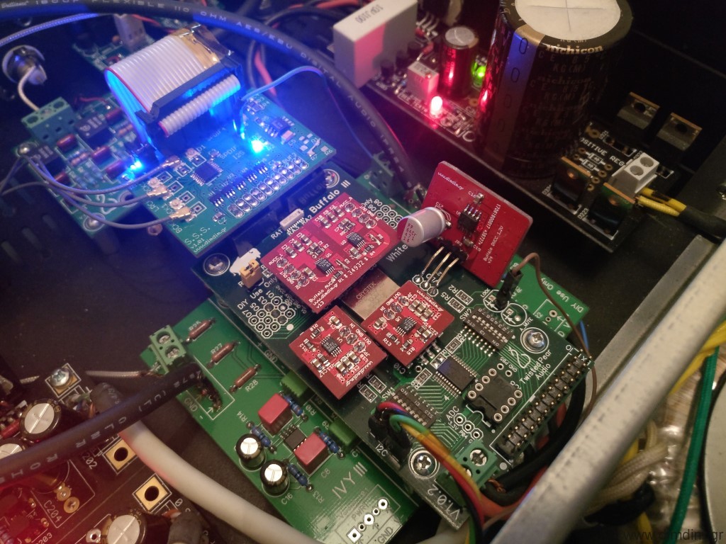
Off came the damaged components..

..to be replaced by fresh capacitors and the brand new ES9028Pro.

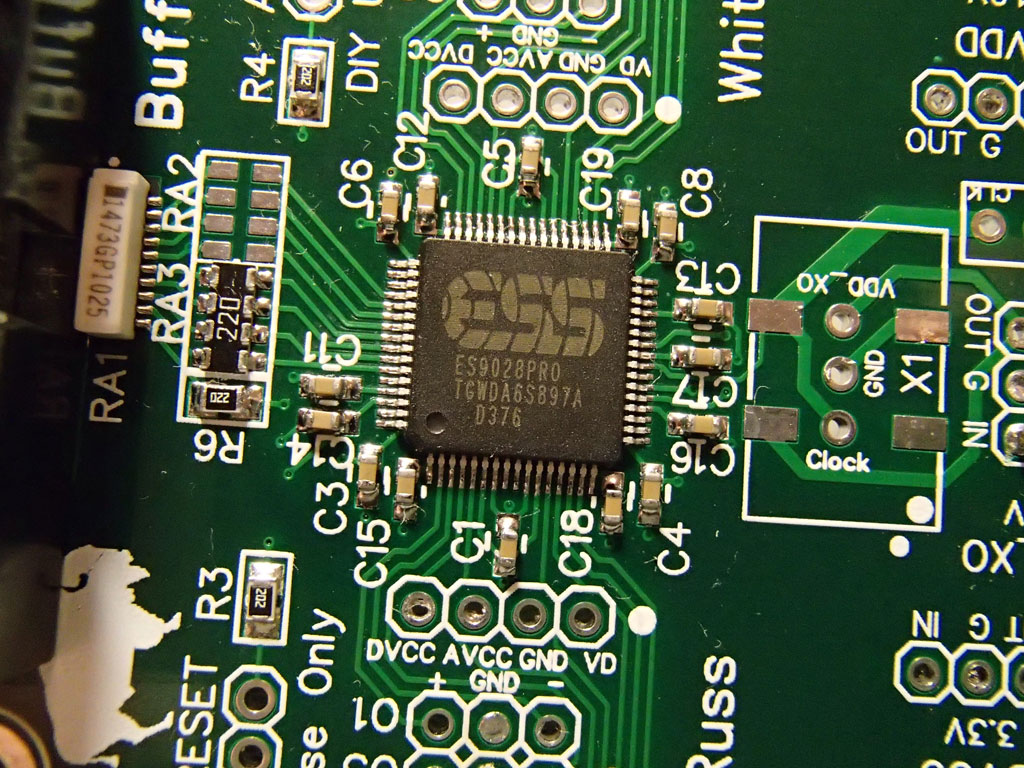
For the time being I chose to not solder on a new Crystek since I could not be 100% sure that the board would work.

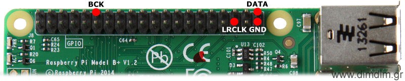
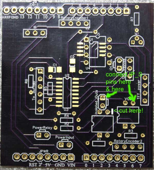
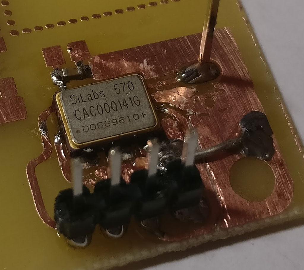
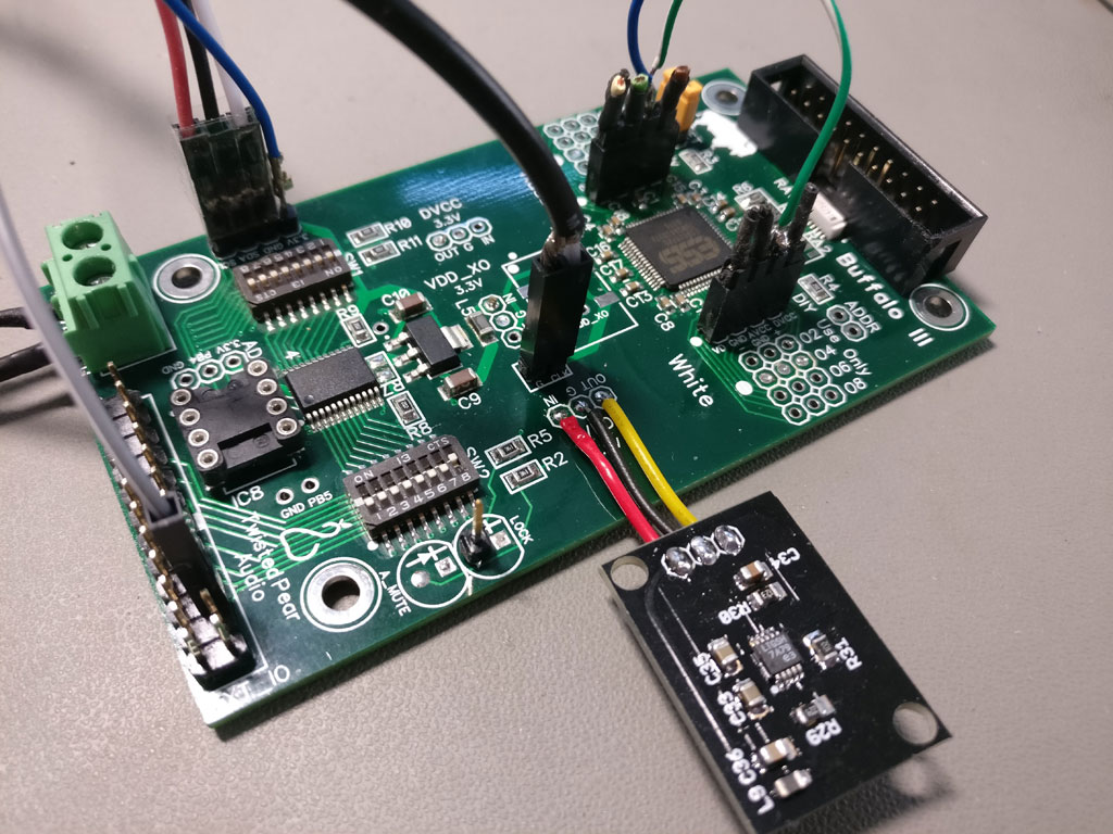
Instead, I soldered on a two pin header to which I connected an Si570 programmable oscillator that I had lying around.

Power was to be delivered by the on-board die-hard 3.3V LDO with a little help from a small PCB holding a LT3042 taking care of the 1.2V.

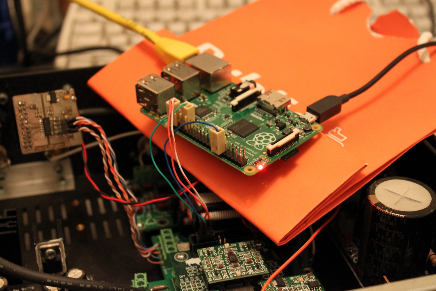
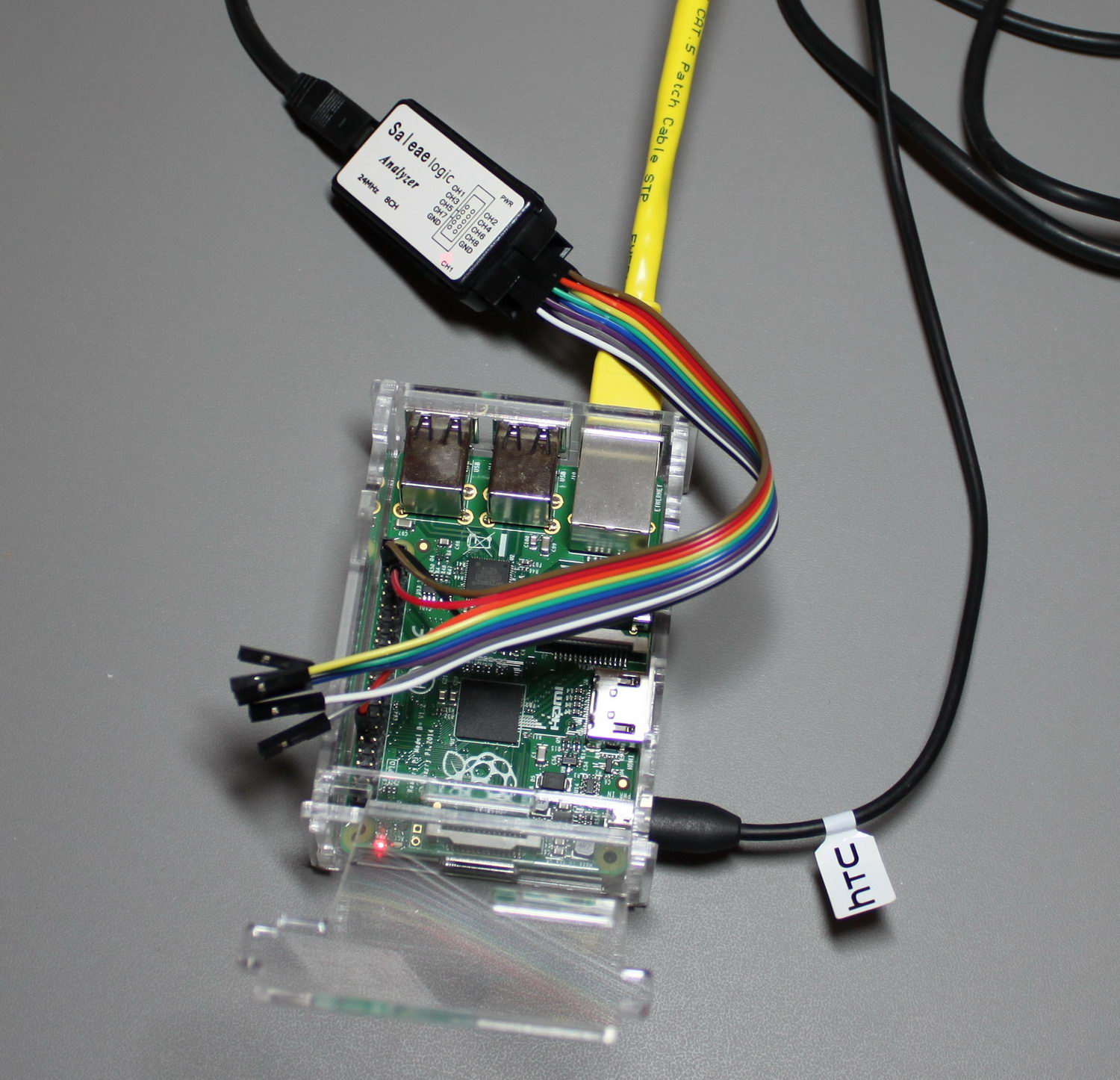
I hooked everything up, connected my Arduino, powered the thing on and loaded an I2C scanner on my Arduino. I did a scan and found a single I2C address. That was not good. I should have found two (one for the on board port expander and one for the ES9028). I double checked my connections, my power, made sure that my Si570 was outputting a proper clock, but still nothing. It was time to go back to the datasheet.

My eye fell on the section pertaining to the Reset pin. It stated that it was an active-low pin and that a system reset could be performed either by pulling the pin low or by a software command. The Buffalo III design called for this pin to be pulled low by default so I hadn’t paid any real attention to it. It turned out that I should have. I soldered a 2 pin header and put a jumper on it. The board immediately came alive and was detected by my I2C scanner. 😀 So, the Reset pin should be pulled up.

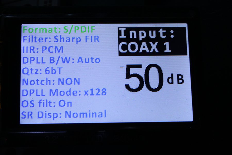
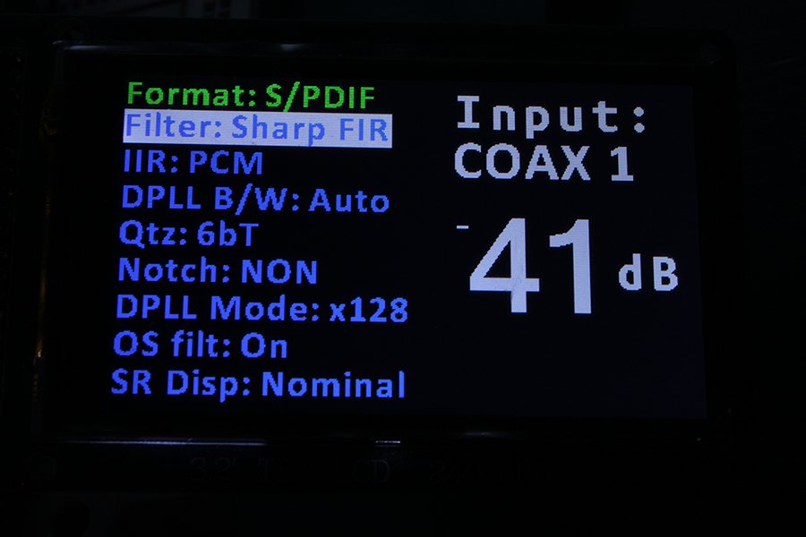
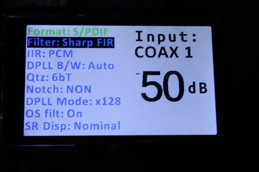
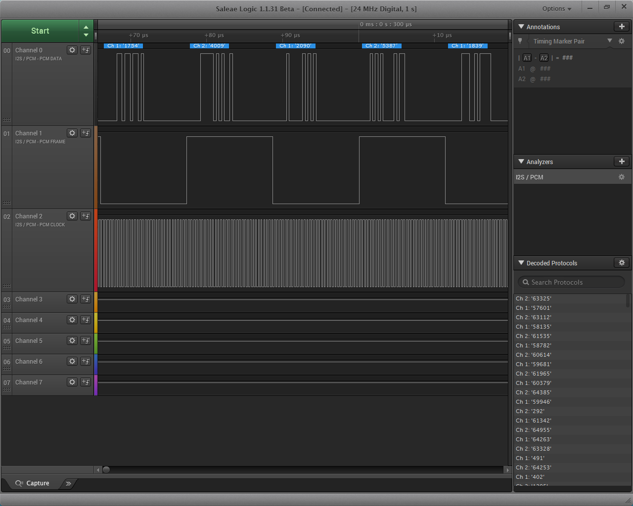
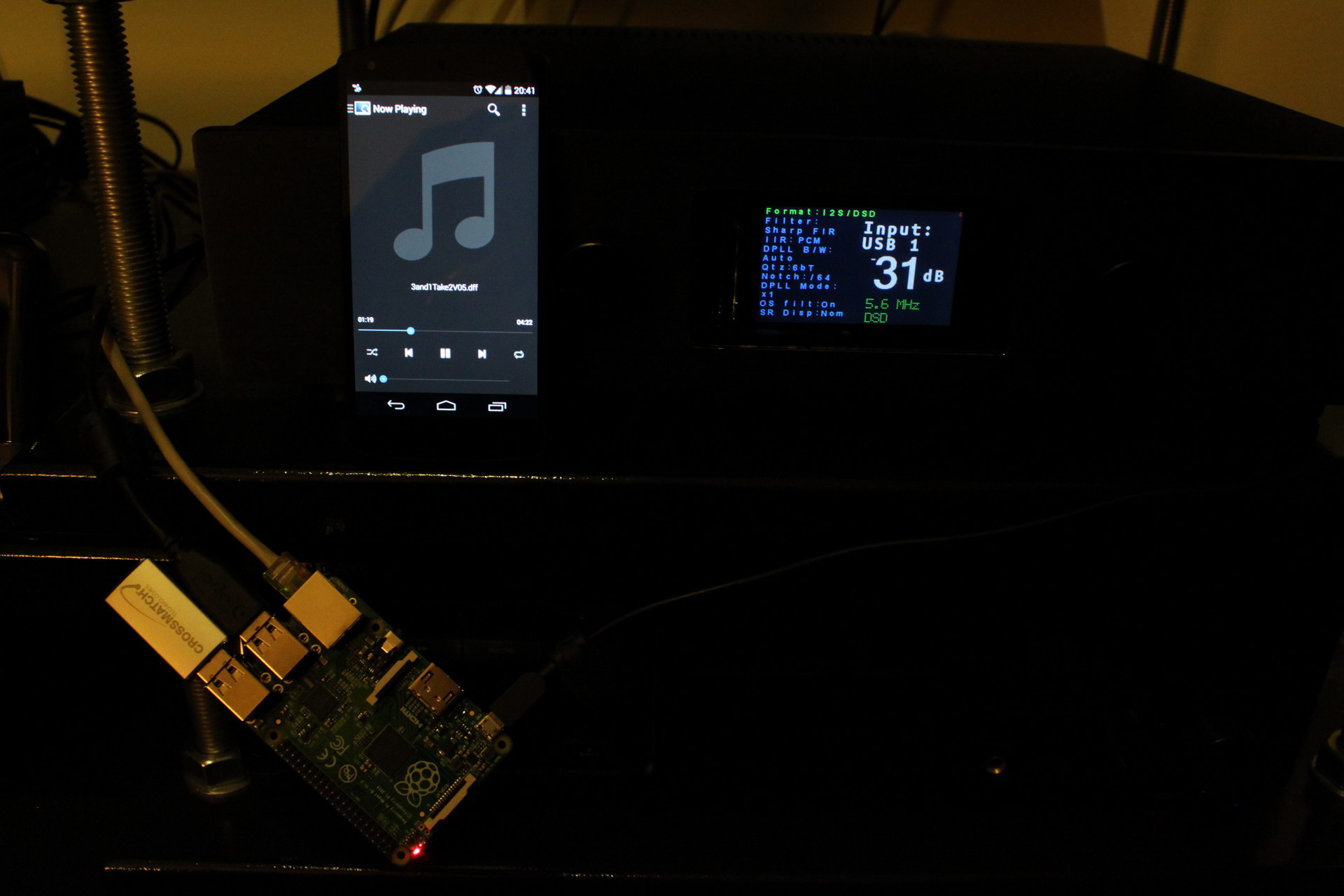
With that out of the way, I connected my test I2S source (a Chinese clone of an Amanero – not as good as an original Amanero but OK for testing and pretty expendable). The DAC locked with no problem into all sampling rates up to 352K and DSD128 (I didn’t bother to try to go higher) and started playing music!

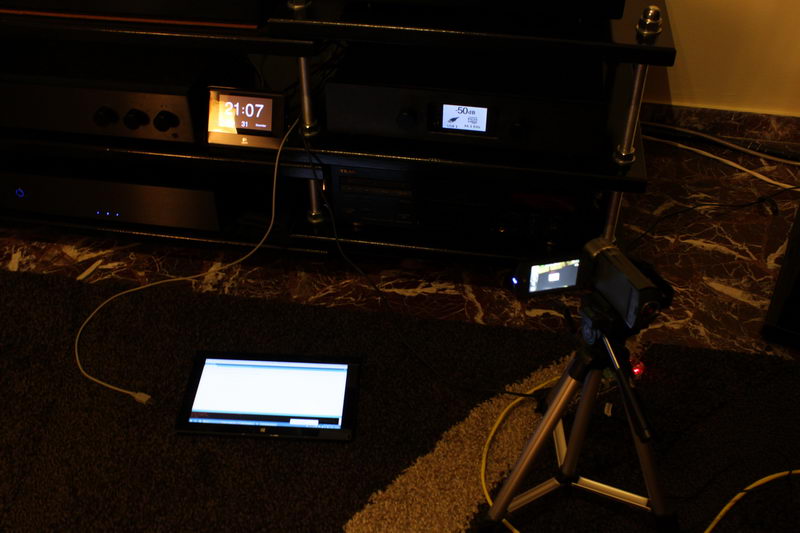
Now I’m waiting for the new replacement Tridents & AVCC module PCBs to arrive so that I can do a proper test vs. my Buffalo III.

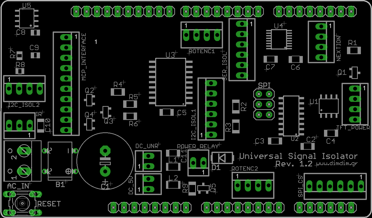
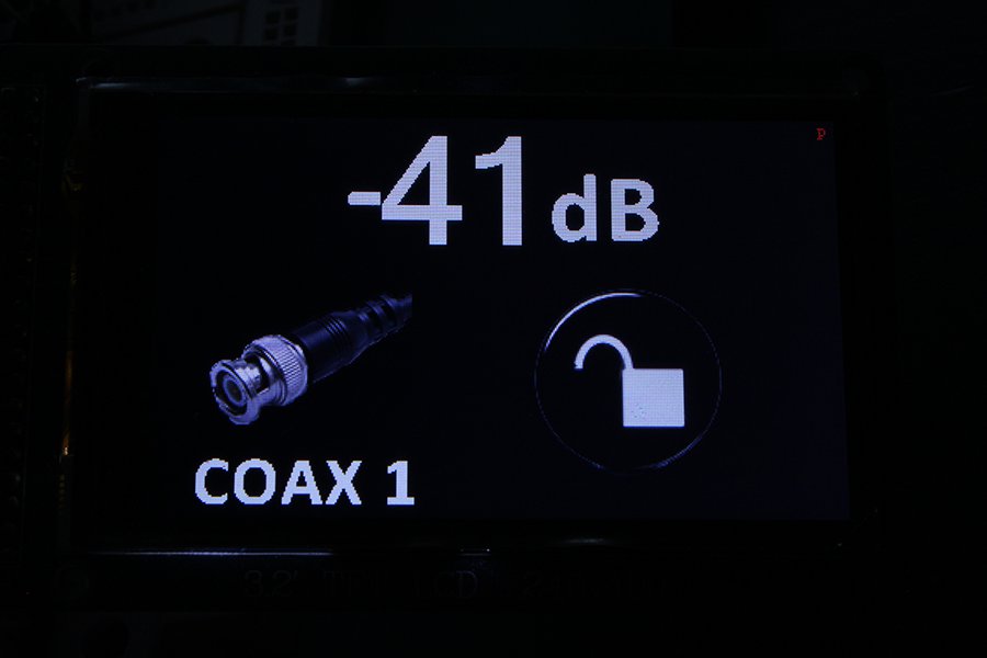
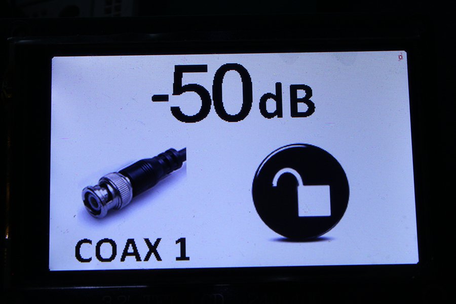
I also need to do a version of my TFT HiFiDuino code for the 9028/9038. Stay tuned.

Ideon Audio 3R USB Renaissance

OK, so this small Greek company comes up with a USB regenerator gadget targeted towards audiophiles.

They claim that it improves audio dramatically. It uncovers lost detail, enhances dynamics, etc.

We’ve heard all that hi-end mumbo-jumbo before, right?

Problem is, this time the gadget actually works. I didn’t believe it either until yesterday, when I was invited to a friend’s house. Also invited were a couple of friends and this little guy:

It was accompanied by its designer, Vasilis of Ideon Audio. Mind you, this is the same Vasilis that is behind the Mamboberry DACs.
I’ve known Vasilis for the better part of 10 years now. We have exchanged some pretty sharp remarks over the years, in regards to our shared hobby, but this time I must admit that he’s really on to something.

The 3R contains a TI chip with a low jitter clock and a bunch of LDOs. It is powered by an SMPS wall-wart (rumor has it that it works even better powered by a linear power supply).
What happens is that the 3R is detected by the PC as a USB device which essentially passes-through the DAC that it is connected to. It works like a USB hub – it’s an active device but it needs no drivers.
It works its magic by regenerating the USB signal using its own low jitter clock and low noise LDO regulators.

The end result is that the DAC manages to literally extract more detail from the music stream, be it from a PC or a Mac based transfort. It doesn’t matter what your DAC is – it will make a positive difference. We tested it with a Buffalo III dac (Amanero as receiver with no isolation) and with an Aune S16 (XMOS receiver, isolation, and FPGA doing FIFO and reclocking). In all cases, introducing the 3R into the chain made for better bass definition, more resolution, and better sound stage.

This is some upsetting stuff. This made me feel the same way I felt a few weeks back when I was auditioning Salas’ system and I could hear audible differences when we changed Foobar’s buffer length from 400ms to 1000ms. This shouldn’t happen, but it does.

I don’t know.. Perhaps this is a sign that I should switch to another hobby.

In conclusion, here is a picture of Darth Vader on the 3R:

If you have a half-decent USB dac and you’re serious about audio reproduction (a.k.a. you’ve already invested in a good sound system) you should get one. Not Darth Vader, the 3R.

Universal Signal Isolator Shield: Rev. 1.2

Since there has been a lot of interest in my Isolator shield these past few months, I have been optimizing its design.

The result of this optimization is this PCB:
Rev.-1.2-pic
It’s called “the Rev. 1.2”.

Nothing major has changed. The pinouts are still the same, the major components are the same, the functionality is essentially the same.

The changes are as follows:

  • New SPI header. It just passes through the SPI signals, nothing more. It does not connect to anything on the board.
  • New SPI_CS header. Useful only if / when connecting SPI peripherals.
  • Reset button. Because you never know..
  • New circuitry for the POWER_RELAY header. It now uses a MOSFET and it includes a diode for the reverse current coming back from the relay’s coil.
  • Decoupling cap for the IR receiver. Not absolutely necessary, but good to have.
  • More decoupling for the DC_UNR input.
  • Ground planes. Lower Arduino noise, at least in theory.

Here is the updated parts placement:
USI-parts-placement-rev1.2

And this is the updated BoM:

[table “” not found /]

Soon I will update the shield’s page with the new info.

Update: TFT HiFiDuino v2.13

I did a little work on the TFT HiFiDuino code, incorporating most of the enhancements I made to the ArDAM1021 code.

v2.13_1

v2.13_4

v2.13_2

v2.13_5

v2.13_3

v2.13_6

These are the enhancements:

  • Option of displaying white text & graphics on black background as well as the “original” look.
  • New encoder code (it requires a new library).

Plus a few minor bugfixes here and there.

The new version of the code is here (v2.13): TFT_HiFiDuino_v2.xx (10513 downloads ) (Note: As always, the code on this page may not be the current one, i.e. there may be a newer version available. The latest version is always up at the project’s official page.)

I will also update the code’s official page with the new version of the code.

TFT HiFiDuino v2.01 + video

As is usually the case, a few bugs crept into the v2 release. So, here is v2.01: TFT_HiFiDuino_v2.xx (10513 downloads ) (Note: As always, the code on this page may not be the current one, i.e. there may be a newer version available. The latest version is always up at the project’s official page.)

Also, here is a video of the code in action:

TFT HiFiDuino v2!

It’s official: Version 2 of the TFT HiFiDuino controller is complete!

There is a number of changes, thus the new version:

  • New minimal display mode as default. Goes into full display when changes are to be made to parameters.
  • Full graphics support in the minimal display.
  • New proportional fonts (TrueType).
  • New IR code. Now supports a much larger range of remote manufacturers.
  • Support of MCP23008 IC to control misc devices.
  • New option to set 0db as default (power-on) volume for connection to a preamp.

The code is (and will remain) compatible with my current shield. (Hint: shield v2 is also coming up!)

New requirements:

Plus the good old UTFT library.

I am including the necessary fonts and bitmaps in the ZIP. The fonts should go into your UTFT & UTFT_DLB directories, usually found in the Windows user’s Documents folders (for example, here: c:\Users\<user name>\Documents\Arduino\libraries\UTFT_DLB\).

The bitmaps should go into your sketch’s folder.

I have included in several places in the code SerialUSB output for debugging purposes. It is commented out in this release for performance purposes. However, it is very easy to re-enable for either debugging or viewing of the IR codes sent to the Arduino. You may use these IR codes to customize the code to support your remote by changing the relevant #define statements in the Remote control definitions section.

Due to code size and performance requirements I’m afraid that from v2 onwards TFT HiFiDuino will only be compatible with the Arduino Due. Sorry, it’s the price to pay for nice graphics. Thankfully, it’s a pretty low price. 😛

You may download it here: TFT_HiFiDuino_v2.xx (10513 downloads ) (Note: As always, the code on this page may not be the current one, i.e. there may be a newer version available. The latest version is always up at the project’s official page.)

I will soon update the code’s official page to v2.

IMG_8600_resize

The Raspberry Pi: Audio out through I2S

There are currently four ways to get audio out of the RPi:

  1. Use the audio out 3.5mm jack. It’s very easy to get it to work, but the sound quality is pretty bad, since it uses PWM to generate the sound. Due to that, its real resolution is in the neighbourhood of 11 bits. We have no use for that.
  2. Use the HDMI port. It works OK, but is useless to us audiophiles.
  3. Use a USB to I2S adapter, such as an Amanero or an XMOS-based device. Now we’re talking. They work quite well, and the quality of the I2S signal is dependent largely on the technology used (CPLD vs. XMOS, etc) as well as the quality of the on-board clocks. The problem is that they add another link to the audio chain, as well as increase the cost. Remember, the RPi is supposed to be a low cost solution.
  4. Use the GPIO pins of the RPi to get direct I2S output. This sounds way more interesting, right? Let’s try that!

According to several sources on the Net, this is the pin out:

Raspberry_Pi_B_Plus_I2S_out

You will probably notice that the RPi does not support MCLK output. This means in practice that your DAC will need to have its own on-board clock (or internal PLL / oscillator or whatever). We can live with that.

Luckily, my Buffalo III has its own clock (of course it does!) and thus can be connected quite easily. Let’s try that:

IMG_8297_resize

Now we have to configure the software for I2S output. For my distribution of choice, Archphile, it’s a piece of cake: http://archphile.org/howto/i2s-dacs-and-the-raspberry-pi/

Audio playback works just fine!

Well, almost fine..

You see, in theory the RPi has a bit of a problem with its I2S output. Since the only clock onboard the RPi is a 19.2MHz crystal, it should have trouble generating proper clocks for its I2S output. For example, for 44.1KHz audio, the LR Clock must be running at precisely 44.1KHz. That is not possible, since the frequency is not a multiple of 19.2MHz. Thus, the frequency can be either 19.200.000 / 435 = 44.138KHz or 19.200.000 / 436 = 44.0366KHz. This is a limitation of the Broadcom BCM2835 in conjunction with the 19.2MHz crystal and there is nothing that can be done.

In order to confirm the theory, I decided to run a few tests. I hooked up my logic analyzer to my RPi, set it up for I2S output, and fed it some 44.1KHz music.

IMG_8453_crop_resize

I took 1 sec worth of samples with my logic analyzer, configuring it for I2S signal. I got this:

logic analyzer 4

The PCM Clock is already appearing a little dodgy. Let’s zoom in:

logic analyzer 5

logic analyzer 6

As you can see, the pulses do not have the same duration. They appear to alternate between two values. So it is obvious that the signal has jitter. A lot of jitter. Since we’re here, let’s have a look at the LR Clock signal as well:

logic analyzer 7

logic analyzer 8

The duration of the pulses appears to alternate between 11.33μS and 11.38μS, giving respectively 44.12KHz and 44.04KHz, values very close to the ones I calculated previously.

So, the theory is sound and the RPi’s clock is not up to snuff by strict standards. What this means is that the RPi’s I2S output is not capable of “Hi End” audio transmission. It is essentially not bit perfect (edit: this is not correct, strictly speaking. It is in fact bit perfect, it is just not “proper”.).

In the real world, chances are that this problematic clocking will not be particularly audible under normal circumstances, say with a normal-specc’ed sound system. But an audiophile should definitely steer clear of the RPi’s I2S output, instead opting for a USB to I2S interface.

The Raspberry Pi: Low cost music streamer

Enter the Raspberry Pi B+:

Raspberry Pi B+

It features:

  • A Broadcom BCM2835 SoC processor running at 700MHz
  • 512MB of RAM
  • A Micro SD slot for storage
  • A 10/100Mbps Ethernet port
  • 4 x USB2.0 ports
  • An HDMI output port
  • An analog audio / composite video output port
  • A 40-pin expansion header, exposing 26 x GPIO ports
  • A camera and a display interface port

Somehow they have managed to cram all that in an almost credit-card sized PCB.

And it costs less than 40€.

It runs Linux (of course..). There is a large number of general-purpose distributions available, as well as a few custom built ones. One of them is Openelec (an XBMC Media Center distro), another one is Volumio (an audiophile music player), a third one is SqueezePlug (it emulates a number of Media Servers, like Logitech Media Server, MediaTomb, MiniDLNA, etc. It also works as a Squeezebox (client)), etc.

So far, my favorite distribution is Archphile, an audiophile linux distribution. It may not have the polished look of Volumio or play 1080p video like Openelec, but is plays music wonderfully through a USB port (or through I2S if you are more of a DIYer).

So, what am I doing with it? I wanted to put a music streamer in my kitchen. I already have two Squeezeboxes in other rooms, so for the kitchen I thought I would try something more interesting.

But along the way, I discovered that it is a lot more useful than that. A very useful (and very rare) feature it has is the ability to bitstream DSD audio (a.k.a. SACDs):

RPi outputting DSD to Buffalo DAC

Raspberry Pi B+ outputting DSD to my Buffalo DAC

So now I’m considering adding an RPi network music transport to my main system.

Buffalo Shield revision for B3SE

As I said, I will release a new revision of the Buffalo shield that will have better support for the B3SE.

Since that will probably take some time, in the meanwhile, this is what B3SE (or 32s or II) owners should do to their shields in order to support the B3SE:

IMG_6908_res_mod

The idea is to connect the photosensor side of one of the optoisolators directly to the IP_S header on the B3SE. In order to do that, you will have to cut one trace on the PCB and solder directly onto one of the optoisolator’s pins. That’s pretty much it.

On the new revision of the shield there will be a jumper where you have to cut the trace plus an extra pin so that you don’t have to solder onto the isolator’s pin.